Original Installation Manual Pendix eDrive
←
→
Page content transcription
If your browser does not render page correctly, please read the page content below
Original Installation Manual
Pendix eDrive

                                 compatible with
                               Pendix.bike PRO App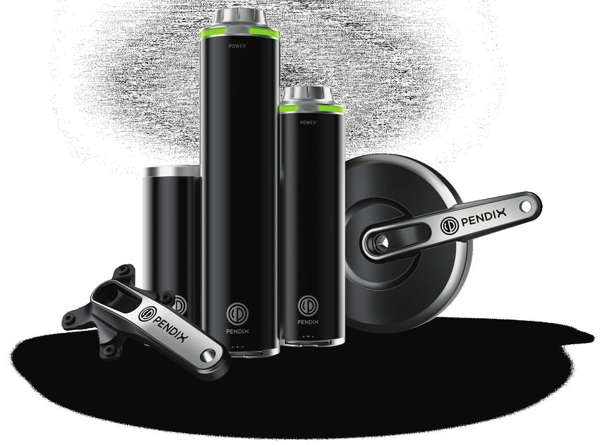
Contents
1. Safety notes . . . . . . . . . . . . . . . . . . . . . . . . . . . . . . . . . . . . . . . . . . . . . . . . . . 3
2. Introduction  . . . . . . . . . . . . . . . . . . . . . . . . . . . . . . . . . . . . . . . . . . . . . . . . . 3
3. Field of application . . . . . . . . . . . . . . . . . . . . . . . . . . . . . . . . . . . . . . . . . . . . 3
4. Scope of supply . . . . . . . . . . . . . . . . . . . . . . . . . . . . . . . . . . . . . . . . . . . . . . . 4
5. Overview components . . . . . . . . . . . . . . . . . . . . . . . . . . . . . . . . . . . . . . . . . 5
6. Installation  . . . . . . . . . . . . . . . . . . . . . . . . . . . . . . . . . . . . . . . . . . . . . . . . . . 6
6.1      Safety at work . . . . . . . . . . . . . . . . . . . . . . . . . . . . . . . . . . . . . . . . . . . . . . . . . . . . . . . 6
6.2      Requirements for installation . . . . . . . . . . . . . . . . . . . . . . . . . . . . . . . . . . . . . . . . . 6
6.3      Special tools required . . . . . . . . . . . . . . . . . . . . . . . . . . . . . . . . . . . . . . . . . . . . . . . . 7
7. Mounting the Pendix components . . . . . . . . . . . . . . . . . . . . . . . . . . . . . . . 8
7.1      Wheel speed sensor . . . . . . . . . . . . . . . . . . . . . . . . . . . . . . . . . . . . . . . . . . . . . . . . . . 8
7.2      Pendix bottom bracket . . . . . . . . . . . . . . . . . . . . . . . . . . . . . . . . . . . . . . . . . . . . . . . 8
7.3      Battery holder . . . . . . . . . . . . . . . . . . . . . . . . . . . . . . . . . . . . . . . . . . . . . . . . . . . . . . 10
7.4      eMaschine . . . . . . . . . . . . . . . . . . . . . . . . . . . . . . . . . . . . . . . . . . . . . . . . . . . . . . . . . 11
7.5      Cable connection . . . . . . . . . . . . . . . . . . . . . . . . . . . . . . . . . . . . . . . . . . . . . . . . . . . 12
7.6      Pendix crank  . . . . . . . . . . . . . . . . . . . . . . . . . . . . . . . . . . . . . . . . . . . . . . . . . . . . . . . 12
8. First ride . . . . . . . . . . . . . . . . . . . . . . . . . . . . . . . . . . . . . . . . . . . . . . . . . . . . 13
9. Mounting addition Pendix eDrive folding bike . . . . . . . . . . . . . . . . . . . . 14
10. Installation check list . . . . . . . . . . . . . . . . . . . . . . . . . . . . . . . . . . . . . . . . . 15
10.1     Comments . . . . . . . . . . . . . . . . . . . . . . . . . . . . . . . . . . . . . . . . . . . . . . . . . . . . . . . . . 17
11. Guarantee conditions . . . . . . . . . . . . . . . . . . . . . . . . . . . . . . . . . . . . . . . . . 17
12. Wiring diagram . . . . . . . . . . . . . . . . . . . . . . . . . . . . . . . . . . . . . . . . . . . . . . 18
13. Technical data . . . . . . . . . . . . . . . . . . . . . . . . . . . . . . . . . . . . . . . . . . . . . . . 19
14. Imprint . . . . . . . . . . . . . . . . . . . . . . . . . . . . . . . . . . . . . . . . . . . . . . . . . . . . . 19
15. EU Declaration of Incorporation . . . . . . . . . . . . . . . . . . . . . . . . . . . . . . . . 20
16. Installation documentation . . . . . . . . . . . . . . . . . . . . . . . . . . . . . . . . . . . . 22
EU Declaration of Conformity . . . . . . . . . . . . . . . . . . . . . . . . . . . . . . . . . . . . . . 23
tightened can break or become loose! This can                    kind, do not use the bike any further and let a
1. Safety notes                                                             cause severe falls and accidents!                                Pendix premium partner check and repair it, if
                                                                                                                                             possible.

In these instructions you will find four different symbols – the   2. Introduction                                                           The Pendix eDrive motor is not designed for
symbol Note provides important information about your                                                                                        use in areas subject to explosion hazard or
new motor and how to use it, the symbol Caution draws              This installation manual describes the installation of the                equivalent.
your attention to possible damage and/ or environmental            Pendix eDrive on a bicycle and is meant for bicycle mecha-
hazards, the symbol Danger warns you against possible
accidents and severe damage, including possible injuries
                                                                   nics, technicians and people with equivalent knowledge and
                                                                   technological comprehension.
                                                                                                                                                                                                     EN
to your person. The symbol Torque marks sections where                                                                            When a Pendix eDrive has been installed into your bicycle, it
a screw connection may only be tightened using a torque                                                                           becomes a Pedelec. It is recommended to only retrofit bicy-
wrench. The torque value given must be adhered to. Whene-                    Carry out the assembly steps described in these      cles that comply with the known bicycle standards, such as
ver you see one of these symbols, there is a risk that one of                instructions only. Do not undertake additional       DIN EN14764, DIN EN14766 or ISO4210:2014.
the hazards described may actually occur! Every warning gi-                  work – no other steps may be undertaken or
ven is in a special box with a gray background for emphasis.                 changes made to the system. Do not take apart                   We have designed your Pendix eDrive
                                                                             or open components! Improper and unprofessi-                    motor in strict adherence to all safety re-
Explanation of symbols                                                       onal mounting of the motor and manipulations                    gulations. In spite of all this, a residual risk will
                                                                             to battery, charging unit and motor involve gre-                always remain.
          Note: This symbol provides information about                       at danger to health and damage of material. In
          how to handle the product or work with                             any such cases, Pendix refuses to accept any
          the respective section in the installation manual,                 responsibility for damage or accidents caused.
          these should always be consulted.
                                                                             For installation of the Pendix eDrive in a bicycle
                                                                                                                                  3. Field of application
          Caution: This symbol warns you against making                      or onto a bicycle frame, expert technical back-      The Pendix eDrive is provided for the following bicycle ty-
          mistakes which can result in damage to material                    ground and experience are required, as well          pes: City- / Trekking- / Touringbikes, Mountainbikes (Race/
          or create an environmental hazard.                                 as special tools and equipment. In general we        Cross-Country), road bike, folding bike, recumbent bicycles
                                                                             would recommend to choose an authorized              and further related types.
          Danger: This symbol stands for a possible dan-                     Pendix premium partner to do the installation.
          ger to your life and/ or health, if relevant instruc-              Read the manual carefully and follow all inst-                 Because of the higher loads the application of
          tions are ignored or not correctly followed. It also               ructions step by step. Pay special attention to                Pendix eDrive in downhill-, freeride-, BMX-cycles,
          draws your attention to the fact that correspon-                   the Safety Notes. Always keep the installation                 dirtbikes and further related types as well as
          ding preventive measures must always be taken                      manual in a safe place, and pass them on to all                operation in competition is prohibited. The usa-
          beforehand.                                                        other persons working with a Pendix eDrive.                    ge in static conditions (dyno, home gym) is also
                                                                                                                                            prohibited.
          Torque: Important screw connection! When                           The Pendix eDrive is not designed for installati-
          tightening up a threaded connection (screws),                      on and effective use in bicycles for children and              Using clipless pedals in combination with Pendix
          the exact torque must be adhered to. The correct                   juveniles up to the age of 14 years!                           eDrive is prohibited.
          tightening torque is either shown on the part in
          question, or you will find it in the table of (torque)             Make sure that the bicycle is in a technical per-
          tightening values on page 52 of this installation                  fect and non-damaged condition. Check all
          manual. You must use a torque wrench to obtain                     components for cracks, breaks, deformations
          the proper torque. Parts which are not correctly                   or heavy wear. If you notice anything of this

                                                                                                                                                                                                 3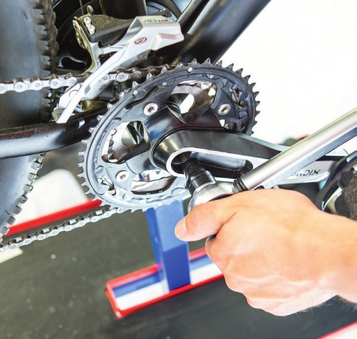
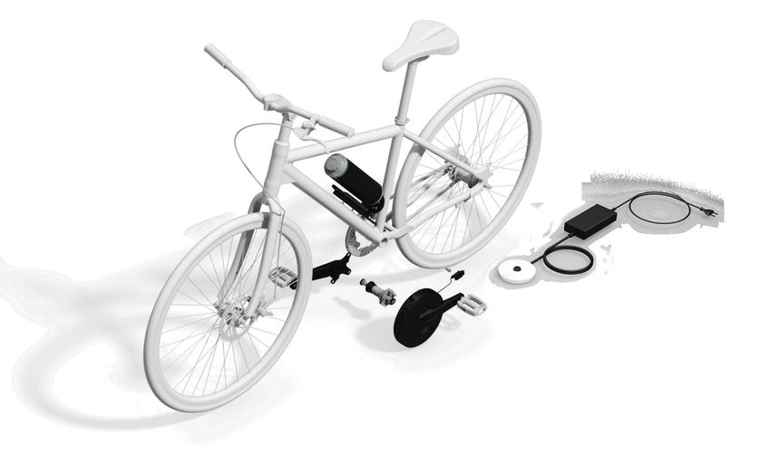
4. Scope of supply                                                                              The overview on the following page shows all components on the bike.

    pos.-no.      description                                                  article no.               eDrive150start      eDrive150      eDrive300       eDrive500   eDrive1000

       1          drive system unit; 250 W                                     A3C.902.140
                                                                                                                                               1
                  preassembled: coupling ring                                  A1C.301.002
       2          crank; 172.5 mm                                              A1C.302.001                                                     1
       3          battery ePower150; 48 V; 13S1P                               B3C.904.173                      1                  1               -             -          -
       4          battery ePower300; 48 V; 13S2P                               B1C.904.071                      -                   -              1             -          -
       5          battery ePower500; 48 V; 13S3P                               B2C.904.071                      -                   -              -            1           2
       6          battery holder                                               A1C.904.022                      -                   -              1            1           1
       7          battery holder for ePower150 (aluminium)                     B3C.904.091                      -                  1               -             -          -
       8          battery holder for ePower150 (plastic)                       B3C.904.092                      1                   -              -             -          -
       -          screws battery holder
                  •    screws battery holder M5x16                             A1C.402.205                                                     1
                  •    screws for connector cover M4x16 self-cutting           A1C.402.211
       9          charging unit Ansmann, 120 W; 54.6 V; 2,2 A                  B1C.904.081                      -                  1               1             -          -
      10          charging unit Ansmann, 200 W; 54.6 V; 3.6 A                  B2C.904.081                      -                   -              -            1           1
      11          charging unit HG Power; 160 W; 54,6 V; 3 A                   B5C.904.081                      -                  1*           1*              1*          1*

      12          charging unit HG Power; 60 W; 54,6 V; 1,1 A                  B4C.904.081                      1                   -              -             -          1

      13          Power Station                                                A1C.904.023                      -                  1**         1**              1**        1**
      14          bottom bracket unit composed of:
                  •    electronic bottom bracket                               A1C.903.030
                  •    electronic bottom bracket fitting unit                  A1C.301.034
                  •    2 spacer ring electronic bottom bracket                 A1C.301.003                                                     1
                  •    wave washer                                             A1C.301.221
                  •    2 crank screws                                          A1C.301.202
                  •    screwed bushing aluminium                               A1C.301.031
      15          assembly set wheel speed sensor
                  •   wheel speed sensor 290 mm / 580 mm                       A1C.903.070.0 / -070.1
                                                                                                                                               1
                  •   mounting kit wheel speed sensor                          A1C.301.207
                  •   spoke magnet

               * replaces Pos. 9/10 - charging unit Ansmann; 120 W/200 W   **charging unit HG Power; 160 W is omitted in pos. 11
4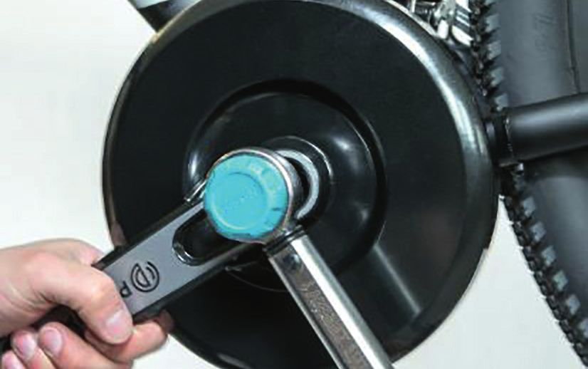
5. Overview components                                                                    (3)/(4)/(5) ePower 150/300/500
                                                                                          13S1P Li-Ion/ 13S2P Li-Ion/ 13S3P Li-Ion battery
                                                                                          voltage: 48 V
                                                                                          capacity: 140 Wh/330 Wh/497 Wh

                                            (6)/(7)/(8) battery holder
                                                                                                                                           (9)/(10)/(11)/(12) charging unit
                                                                                                                                           60 W/120 W/160W/200 W
                                                                                                                                           for 48V Li-Ion battery
                                                                                                                                                                                             EN
                                                                                                                                           input value: 100-240 V AC; 50 Hz;
                                                                                                                                           output values: 54,6 V DC; 60 W/120 W/160W/200 W

        (2) crank
        crank length: 172,5 mm
        pedal thread: 9/16“ x 20 RH (FG 14,3)
        connection diameter chain wheels: 104/64 mm

                                                                                                                             (13) power station

                                                          (14)bottom bracket unit
                                                           electronic bottom bracket
                                                                           square shaft                      (15) wheel speed sensor set
                                                                  shaft length: 128 mm                       wheel speed sensor
                                   bottom bracket thread: BSA 1,375“ x 24 TPI LH (FG34)                      spoke magnet
                                                                crank thread: M8x1 RH
                                                electric bottom bracket fitting unit
                                   bottom bracket thread: BSA 1,375“ x 24 TPI RH (FG34)
                                             spacer ring electronic bottom bracket                 (1) eMaschine
                                                                       lock washer                 nominal power: 250 W
                                                                       crank screw                 crank length: 172,5 mm
                                                       screwed bushing aluminium                   pedal thread: 9/16“ x 20 LH (FG 14,3)
                                                                                                                                                                                         5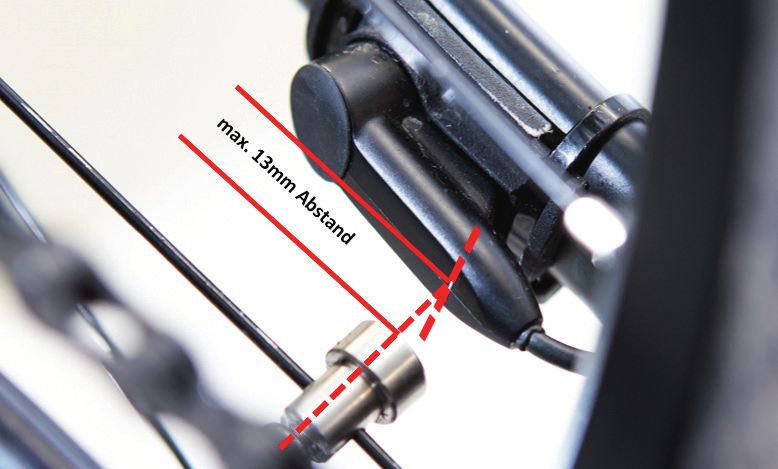
Frame material
6. Installation                                                 Pendix eDrive can be attached to all metal frames. If you
                                                                wish to mount a Pendix system to a frame consisting of other
                                                                materials such as carbon, wood, etc. please consult our Pen-
Please use the checklist (see section 10) and the online ins-   dix Service Department before installation.
tallation video to check the bike and the installation!

                                                                BSA bottom bracket housing with following dimensions
6.1 Safety at work                                              diameter:           33,7 mm – 34,0 mm
                                                                width:              68 mm oder 73 mm +/- 0,2 mm
Wear suitable work clothing such as gloves and solid shoes      thread:             BSA 1,375“ x 24 TPI (FG34)
when mounting the Pendix eDrive. Attach the bicycle frame       Check the diameter of the bottom bracket housing: The inte-
firmly to a suitable frame holder. Always use suitable tools    rior diameter must measure between 33.7 mm and 34 mm.
and equipment meeting good quality standards.
                                                                Check width and condition
                                                                The width of the bottom bracket housing must be either 68
          If you are not sure about how to put the above        mm or 73 mm. In each case with a tolerance of +/- 0.2 mm.
          safety notes into practice, information on            The bottom bracket housing should be smooth and free of        Testing the crank
          the subject of safety at work is easily obtainable.   paint or coating residues. The threads must be aligned and     Check to see that the available chain wheels fit round the
          Consult for example relevant locally applicable       free of dirt.                                                  crank.
          legal requirements, safety measure guidelines                                                                        The following illustration shows the right-hand crank. It also
          and / or regulations, for example in the internet.                                                                   gives the connection dimensions for chain wheel fitting.

          For your safety, the battery must not be connec-
          ted when installing the motor. Do not place the
          battery in its holder until you have finished as-
          sembly / mounting work.

          Never use a high-pressure cleaner to clean your
          Pendix eDrive motor components. Warning: by
          doing so, water can intrude into the system and
          destroy it.                                           Eccentric bottom bracket
                                                                Should there be an eccentric bottom bracket in the bike,       All commercially available chainrings with a connection dia-
                                                                please take care of exchanging the eccentric bushing made      meter of 104 mm can be used, single and multiple sprocket
6.2 Requirements for installation                               of plastic by a model made of aluminum. Plastic eccentric      wheels are compatible. You can install all commercially avai-
Before installing the Pendix eDrive, you have to check if the   bushings are not approved by Pendix.                           lable pedals with 9 / 16“ x 20 RH (FG 14.3) right hand thread.
bicycle frame fulfills the requirements.
                                                                Maximum rear structure width                                   After the installation of the crank, the length of the chain
          If your bicycle frame does not meet the described     Caution: in the case of fully suspended rear structures,       line (catenary) is 49 mm, which makes it possible to use the
          prerequirements, we cannot assume                     keep in mind that the rear structure does not turn centrally   most common gear shifting systems. When the installation
          any guarantee.                                        around the bottom bracket as in most cases!                    is completed, the derailleur should be checked and if neces-
                                                                                                                               sary should be adjusted.

6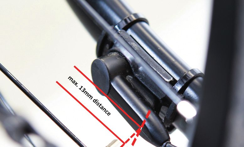
Checking the position of the battery holder                              If your frame has no thread for a bottle holder:                  We strongly recommend to use a dynamometric
The holder for the battery should be attached either to the              Please use the Pendix clamp mounts. Do not                        key for mounting the components in order to
down tube or the seat tube. Already available attachment                 drill holes in very light / thin-walled frames and                make sure that the screws are tightened with the
holes for a standard drinking bottle holder may be used for              especially frames made of composite materials                     specific torque.
attachment of the battery holder. An alternative mounting                (carbon frame)! In this case, please do not use
option, if there are no screwed fixing points, is the Pendix             clamp mounts. Drilling holes in such cases can
clamp mount. It is not contained in delivery scope of the                cause broken frames, falls and severest injuries.       Disassembly of already mounted components
standard set, but can be ordered at Pendix with Art.Nr.                                                                          Before you start installing the Pendix eDrive, you must remo-
A1C.904.021.                                                                                                                     ve the following parts from the bicycle:
                                                                                                                                 • Crank on the left
                                                                                                                                                                                                  EN
         Pendix suggests to use the existing holes in the      Checking the gear hub                                             • Chain guard, if available
         frame for the installation. The drilling of new       When the Pendix eDrive is used with a gear hub, one has to        • Crank on right (including chain wheel)
         holes can weaken the frame: it is a decision that     pay attention to wether or not the circut is activated for a      • Bottom bracket
         must be made by the technician. Pendix can as-        torque of 65 Nm. If necessary, please ask a retailer or the ma-
         sume no responsibility for the safety / duration      nufacturer of the gear hub about that. The maximum torque         Proceed as follows:
         of new attachments and resultant possible frame       can be reduced through the Pendix.bike PRO App.
         damage.                                                                                                                 1.   If the pedals are to be used again, you must remove
                                                                                                                                      them as first step.
                                                                                                                                 2.   Remove the left crank arm.
                                                               6.3 Special tools required                                        3.   Remove the chain guard, if present.
                                                               In order to mount the components, the following special           4.   Remove the right-hand crank arm including the chain
                                                               tools are necessary and can also be ordered from Pendix.               wheel.
                                                                                                                                 5.   Now take out the bottom bracket.
                                                                Mounting the Pendix eDrive
                                                                                                                                 Please also use the online installation video. Access data you
                                                                Bottom bracket tool                                              get from Pendix.
                                                                left and right side
                                                                1 / 2“ connection                                                          Modern bicycle technology is high tech! Working
                                                                                                                                           in this field demands special training, knowledge,
                                                                                                                                           experience and special tools as well!

                                                                crank puller

     In the case of a full suspension frame,
     neither battery nor battery holder may                     assembly help
          come into contact with any other parts of the         bottom bracket
          construction due to suspension movements.
          Check to see that sufficient cable length is avai-
          lable for a correct and safe attachment of the
          battery holder.

                                                                                                                                                                                             7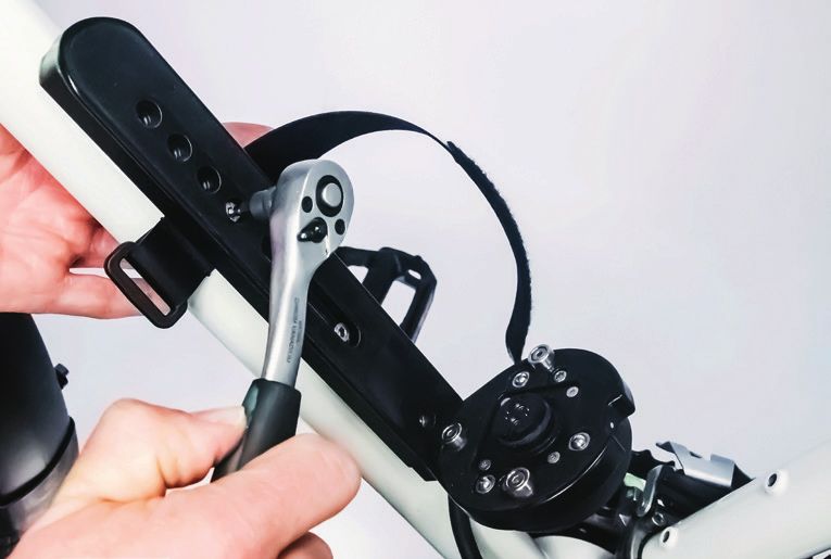
Following this, lay out the cable along the chain stay as far
7. Mounting the Pendix eDrive components                                                                                      as the bottom bracket case and attach it with cable ties as
                                                                                                                              shown. At this point, the cable end will first of all be hanging
                                                                                                                              free in front of the bottom bracket case.
          When laying out cables, make sure they do not          As moving part of the sensor, you must now attach the mag-             Please not that for a safe function of the sensor,
          come into contact with sharp edges,                    net to a spoke and position it correctly facing the main                that it is positioned parallel to the spoke
          extreme bends or corners or rotating parts. Make       sensor.                                                                in the point where the magnet runs through the
          sure you don’t put pressure on the cable. If the                                                                              sensor.
          cables are not tight or under any strain, there                 The distance between magnet and sensor
          is a danger of broken or torn cables or else. To                may not exceed 13 mm.                                          In case that the standard cable is too short
          avoid damage to a cable, you should attach it in                                                                               for your bicycle, you can order a longer cable
          a way that it does not come into contact with the                                                                             in our online shop or through another order
          wheel. Especially in cases where bicycles have                                                                                channel that you already know.
          full suspensions, the distance between frame
          and rear structure changes constantly. Please
          ensure that the cable length is enough.

          When tightening screw connections, always ad-
          here to the exact torque required. For this, you
          must use a regulation tested torque wrench. Only
          in this way, safe and correct assembly work can
          be guaranteed.

7.1 Wheel speed sensor
                                                                 1st Generation Speed Sensor - Orientation to the             7.2 Pendix bottom bracket
Attach the wheel speed sensor to the left chain stay using the   vertical marking                                                       Make sure you do not damage the cable
supplied cable ties. If you have a 1st generation speed sen-                                                                             when mounting the electronic bottom bracket
sor, use the supplied holder to screw the speed sensor to.                                                                              unit. Before installing the electronic bottom
                                                                                                                                        bracket, grease the ball bearings (remove pre-as-
                                                                                                                                        sembled part 06 from the bearing, see next page)
                                                                                                                                        the threads as well as the bottom bracket fitting
                                                                                                                                        with standard bicycle grease.

                                                                                                                                        Do not use grease when installing your
                                                                                                                                        Pendix eDrive into a frame made of fiber
                                                                                                                                        materials (carbon frame)! Use standard carbon
                                                                                                                                        assembly paste instead.

                                                                                                                                        Magnetic fields destroy the electronic bottom
Speed sensor of the 1st generation                               2nd Generation Speed Sensor – Orientation to round                     bracket. Please keep the battery plug of the char-
The 2nd generation speed sensors already have the holder         Pendix logo                                                            ging unit, the spoke-mounted magnet and other
integrated in the sensor housing.                                                                                                       magnetized objects away from the electronic
                                                                                                                                        bottom bracket at all times.

8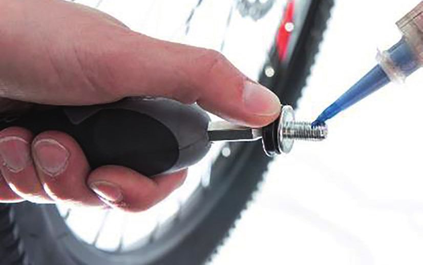
Make sure that the tool slides out of the
                                                                                                                                          housing without any increased resistance.

                                                                                                                                5. /6. Now fasten the electronic bottom bracket on the
                                                                                                                                       other side by turning in the screwed bushing (No.1 in
                                                                                                                                       drawing top left).
                                                                                                                                6.
                                                                                                                                            When performing this step, turn the electronic
1   screwed bushing aluminium 4        electronic bottom bracket
                                                                                                                                            bottom bracket into position by hand only. (Do       EN
                                                                                                                                            not tighten using a tool yet.)
2   spacer ring                  5     wave washer
3   installation tool electronic 6     bottom bracket mounting                     supplied in preassembled condition           Push the bottom bracket as far as possible in direction of the
    bottom bracket                                                                                                              just mounted screwed aluminium bushing.

         For assembly, Pendix recommends the use              1.    Insert the installation tool in the bottom bracket          7.   As final step, use a torque wrench to tighten the
         of installation tool (No. 3). You can order it             housing from the right-hand side (in driving directi-            bottom bracket on the left side to a torque of 60 Nm
        from the order channel that you already know.               on), and push in as far as it will go.                           +/- 3 Nm.
        We can assume no responsibility (guarantee) for                   When doing this, make sure that the tool
        damage to the Pendix bottom bracket caused by                     slides into the case without meeting any              After installing the electronic bottom bracket, make sure
        using a different tool.                                          increased resistance. If you notice any resistance,    that the shaft turns freely without showing any resistance.
                                                                         remove any disturbing elements in the bottom
        Please check, if the bottom bracket has a width                  bracket housing by filing or grinding. Make sure                 In the housing of a BSA bottom bracket, the-
        of 68 mm or 73 mm. In case of a bottom bracket                   not to damage the bottom bracket thread.                         thread on the right hand side (in driving direction)
        with 68 mm, you require on the right and left                                                                                     is a left-hand thread. Screw the bottom bracket
        side one spacer ring each.                                                                                                        on the right side by tightening to a torque of
                                                                                                                                          15 Nm +/- 2 Nm.
                                                               2.   Push the electronic bottom bracket from the left-
                                                                    hand side (in driving direction) into the bottom
                                                                    bracket housing. Make sure that it slides easily into the
                                                                    assembly tool without damaging the cable in doing so.
                                                                                                                                                15 Nm +/- 2 Nm               65 Nm +/- 3 Nm
                                                               3.   Push the bottom bracket mounting (No.6) into the
                                                                    bottom bracket housing by turning it.
                   *

                                                                                                                                          Please pay attention to mount a standardized
                                                                                                                                          chain guard, which is conform to standard
                                                              4.    After tightening the electronic bottom bracket on the                 DIN EN ISO 4210-2.
                                                                    left side by hand, remove the installation tool from the
                                                                    bottom bracket housing by carefully pulling it out.
                   *

           * is applicable with or without chainguard                                                                                                                                        9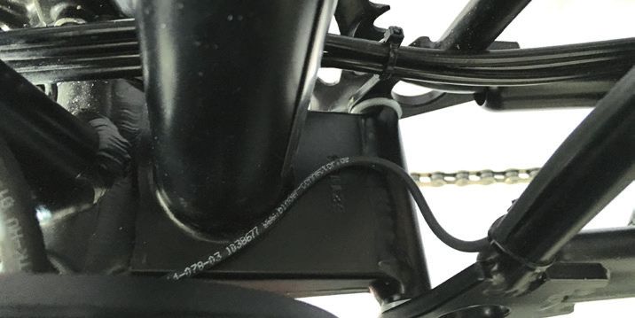
7.3 Battery holder                                                        If your frame has no thread for a bottle holder:      Battery holder for eDrive150
                                                                          Please use the Pendix clamp mounts. Do not
To attach the battery holder to the bicycle, use the threads              drill holes in very light / thin-walled frames and    The eDrive150 comes with a special aluminium battery hol-
for a bottle holder if present. You can freely choose its po-             especially frames made of composite materials         der for ePower150.
sition on the frame by effectively using the available holes              (carbon frame)! In this case, please do not use
in the battery holder, but make sure that that you have                   the clamp mount. Drilling holes in such cases can               The aluminium battery holder for ePower150
enough space below the holder so that, later on, you have                 cause broken frames, falls and severest injuries.               can also be used with ePower300 and 500
room to pull the U-bend out for the lock of the battery in the                                                                            batteries. For this purpose, the installation of an
one direction and room to remove the battery in the other                                                                                 accu strap Art. No. B2C.904.071 (not included in
direction.                                                                                                                                the scope of delivery of the Pendix eDrive150) is
An alternative mounting option, if there are no screwed fi-      Battery holder for eDrive150start                                        recommended.
xing points, is the Pendix clamp mount. It is not contained
in delivery scope of the standard set, but can be ordered at     The eDrive150start comes with a special plastic battery hol-
Pendix with Art.Nr. A1C.904.021. You can find further informa-   der for ePower150 with a accu strap.
tion in spare parts and accessories list.

          Where a full suspension frame is present, the
          battery and the battery holder must at no
          time come into contact with other parts of the
          bicycle structure.                                                                                                    Battery holder for ePower150 (aluminium)
          Make sure there is sufficient cable length to at-
          tach the battery holder correctly and safely (to                                                                                First screw the lower battery holder screw into
          compensate for suspension movements).                                                                                           the battery holder to fix it to the bicycle frame.
                                                                 Battery holder for ePower150 (plastic)                                   Fix the accu strap with the upper battery holder
          Screw the battery holder on using the two                                                                                       screw between the battery holder and the frame.
          supplied M5 screws to a tightening torque of                    First screw the lower battery holder screw
          4.5 Nm + / - 0.5 Nm. Use a screw locking (liquid,               into the battery holder to fix it to the bicycle
          mid-strength) with both screws.                                 frame. Fix the accu strap with the upper battery
                                                                          holder screw between the battery holder and the
                                                                          frame.

                                           4,5 Nm +/- 0,5 Nm

                                                                                                                                Installation of the accu strap

10
7.4 eMaschine The motor is mounted on the left side of the frame. Position
it first of all loosely in order to find out whether the cable of
Grease the square shafts of the bottom bracket wheel speed sensor and electronic bottom bracket are posi-
shaft before mounting the engine and the tioned in the right place, so that they can be plugged into the
crank. motor. For this the grooves of the bottom bracket mounting
in which the cables are attached must be accurately in line
Lay out the cables of the wheel speed sensor and of the elec- with the grooves in the motor.
tronic bottom bracket in the provided ring of the bottom bra-
cket mounting, and position them directly beside each other
in the upper section in two of the provided grooves in the
EN
bottom bracket mounting. The cables should have approxi-
mately 30 mm free length.
Pendix It does not
Montage matter which cable is
Tipps
on the left or right side. Installation Advice
Pendix
If this arrangement fits, the motor can be attached imme-
diately by screwing it on. If it does not fit, you must remove
the motor again and either continue turning it and placing it
back on, or lay out the cable again so that it meets up with
68 mm
the correct position for it to be connected to the motor.
15 Nm +/- 2 Nm 65 Nm +/- 3 Nm
60
Hold the motor tightly in position, it is heavy!
Montagefett // Grease 32 Nm +/- 2 Nm
Then plug the eMachine on the bottom bracket shaft. The Screw the pedal into the crank. Grease the
gearings of the torque support and the eMachine have to thread. Make sure that the pedal on the left
gear into each other. side is attached using a left-hand thread. In this
case, the direction of tightening is anti- clockwi-
Please note by putting the motor, that the cou- se. The tightening torque is 35 Nm +/- 2 Nm.
73 mm pling elements meshing each other. The motor
flange on the back, where are the grooves for the
15 Nm +/- 2 Nm
65
60 Nm +/- 3 Nm
sensor cables are in, should cover the ring, where
the sensor cables are layed in.
Now you can screw the motor up with the sup-
plied crank screw and tighten it at a torque of 32
Nm +/- 2 Nm. The screw thread should already
have a thread locking for safety. If no locking is on
the thread, use a standard liquid screw locking
(medium-strength).
35 Nm +/- 2 Nm
117.5 Cable connection bicycle is a full suspension bike make sure that the cable is
not crushed or abraded during suspension motion!
As shown in the illustration (side before, middle below),
insert the plug of the wheel speed sensor and electronic 32 Nm +/- 2 Nm
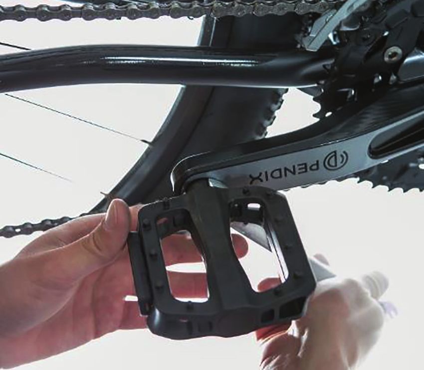
bottom bracket into the motor in the two fittings. It is not 7.6 Pendix crank
important to know which plug must be used for either of the You must attach the chain wheels before attaching the crank
sensors, the motor automatically recognizes each sensor. to the bicycle.
Using the supplied M4x10 Torx-screws, attach the
connector cover to the battery holder from below
and tighten to a torque of 2.4 Nm +/- 0.2 N.
Now screw on the right-hand pedal in clockwise
motion to a torque of 35 Nm +/- 2 Nm.
Tighten the chain wheel screws to a torque of
9 Nm +/- 2 Nm.
The chain wheels and pedals are not delivered
with the Pendix system. In other words, you can
use these parts of your bicycle if their dimensi-
ons agree with the details given in the chapter 5.2
„Requirements for installation“.
Attach the right-hand crank with assembled
chain wheels and with applied chain on the
greased square shaft section. Tighten the crank
using the supplied crank screw to a torque of 32
Nm +/- 2 Nm. The screw thread should already
have a thread locking for safety. If no locking is on
According to length and accessibility, you can lay out the ca- the thread, use a standard liquid screw locking. 35 Nm +/- 2 Nm
ble along or beside the frame tube. If necessary, fix it with ca- Caution: check this crank for correct positioning
ble ties. When laying out and attaching the cable, make sure opposite the crank on the other side.
it does not come into contact with the motor, the pedals and You have now completed assembly of the Pendix eDrive.
rotating parts! The cable may otherwise be damaged. If the Please continue with chapter 8. First ride.
12The disassembly of the Pendix eDrive takes place in reverse
sequence of the described steps. 8. First ride
Check the correct and safe function of the After completing installation and switching on the Pendix
gearshift before the first ride. Also check for system for the first time, the motor control system runs an
correct and safe gear change function. The chain automatic calibration. Thus, when switching on for the first
wheels may have a slightly different position time, the calibration mode is indicated by a blinking green
than before, this means a new adjustment of the light on the LED display. To calibrate, please ride your bicyc-
gear change function may be necessary. Only
ride if gears change without difficulty.
le during this blinking phase for at least 300 m (about 1,000
feet). In the beginning, the drive system (motor) is not yet
EN
Make sure the crank and the chain move without supporting. Try to ride as steady as possible keeping to the
contact at all gear levels inside the chain guard. same speed. As soon as the motor has finished calibrating
successfully, the LED display shows a permanent green light
Gear changing systems are safety-relevant and the motor is supporting. Please ride another 1,000 m
components! All mechanical and adjustment with motor support for fine calibration.
work which is not carried out professionally by a
specialist makes riding your bicycle dangerous! After some first rides it can happen due to pro
When adjustments are faulty, the chain of your duction process, that there occurs some oil
bicycle can drop off and cause accidents through on the motor. This is no failure and has no interfe-
falling. rence on the functionality of the system. Its only
excessive grease from sealing installation and
can be wiped off.
The calibration of the system is only possible
by riding. The calibration on the workstand is not
designated and will not bring positive result.
13Bottom bracket mounting: The inner flange of this part
9. Mounting addition Pendix got removed by mechanical reworking.
eDrive folding bike
Hints
Please use the original installation manual for mounting the
Pendix eDrive. In this mounting extension you will find all infor-
mation you need to mount the Pendix eDrive on a folding bike.
Pendix eDrive folding bike version To 7.3 Battery holder
The Pendix eDrive folding bike version differs in the following Please use the Pendix clamp mount for installing the battery
points: holder to the bike. The manual for clamp mount is included
Mounting hints in every set.
Motor flange: The flange on the back side of the engine be- The numbering in this mounting addition refers to the Pen-
comes reworked mechanically so, that only one half of the dix installation manual and give hints at the relevant points. To 7.4 Drive system unit
flange is existing The eMachine is mounted like described under 7.4. With
that you have to make sure, that the motor got positioned
To 7.1 Wheel speed sensor with the existing flange on the motor above the bottom bra-
In the folding bike kit, there is a speed sensor with cable cket. Due to the removed flange below the bottom bracket,
length of 580mm included. Positioning the sensor on the you get the space for full folding functionality of the folding
upper strut and run the cable along the strut like showed in bike. It will not work always to mount the flange like in the
the following picture. following picture, with exact orientation to the horizon-
tal, but most of the flange should be positioned above the
horizontal.
the hor
izontal
Take care of laying the cable in a way, that with folding the
rear wheel, there is no stress to it. For that, lay a small loop in
the area of the seatpost.
Please continue with the further steps of the installation un-
Please be carefully with the first try of folding for checking til the installation is finished.
the space and the needed length of the cable without da-
maging it.
1410. Installation check list
In order to minimize the risk of liability for commercial fitters, we recommend the documentation of the installation using the “installation report” function, which is integrated
in the Pendix.bike PRO App!
Before installation: inspection of safety-relevant components on the bicycle
If there are former damages on safety-relevant components identifiable that do not allow a safe operation, please desist from installing the Pendix eDrive as long as check
the deficiency on the affected components is not remedied.
EN
brakes (at least two brakes existing, functionality, wear)
fork (age, visible damage, deformation)
frame (age, visible damage, deformation)
handlebar (age, visible damage, deformation)
tires (flaws, wear)
rims (visible damage, deformation)
Before installation: inspection of requirements for Pendix installation check
bottom bracket BSA thread / bottom bracket width 68 mm or 73 mm
bottle mounts existing → if not: using Pendix clamp mounts
installation space for battery & battery holder (down tube trapeze frame)
chainwheel(s) with correct fitting dimension for crank (Ø104/ 64 mm bolt circle)
frame material metallic? No → consultation with Pendix service
cable length needed from motor through battery holder 250 mm/ 500 mm
cable length needed from wheel speed sensor through motor 290 mm/ 580 mm
During the installation: all installation works have to be done without battery inserted! check
wheel speed sensor mounted and wires placed according to installation manual
spoke magnet positioned and mounted according to installation manual
bottom bracket thread greased
spacers on bottom bracket according to installation manual at
68 mm housing width: used!
73 mm housing width: not used!
15bottom bracket mounted with correct torque
right: 15 Nm ± 2 Nm
left: 65 Nm ± 3 Nm
bottom bracket turns free without increased resistance
battery holder mounted with correct torque → 4,5 Nm ± 0,5 Nm
square shaft left and right on bottom bracket greased
electric motor mounted with correct torque → 32 Nm ± 2 Nm
pedal mounted with correct torque to the motor → 35 Nm ± 2 Nm
sensors plugged to motor according to installation manual
battery plug mounted with correct torque to holder → 2,4 Nm ± 0,5 Nm
chainwheel(s) mounted to crank with correct torque → 9 Nm ± 2 Nm
crank mounted to bottom bracket with correct torque → 32 Nm ± 2 Nm
pedal mounted with correct torque to crank → 35 Nm ± 2 Nm
after installation: Ensure that all components move freely check
inspection of clearance between all components, e.g.
no contact between motor sealing ring and chain brace
deflecting Fully MTB → no contact with other components
center kick stand → swing out → contact with motor? Yes → mount other kick stand
wires do not shuffle on rotating parts
gearing/ chainline/ try all gears, possibly adjust gearing
first activation according to installation manual
test run
For installation by commercial fitters only: documentation / handover to customer check
fill in handover documentation + bicycle identification in bicycle manual
(page U5, U6) and copy for your own retention
fill in declaration of conformity and enclose to bicycle manual
stick type label CE “EPAC EN 15194” on bicycle
give installation manual, system manual and bicycle manual to customer
instruction for customer on the bicycle
filled in retailer check list for your own files
1610.1 Comments
EN
11. Guarantee conditions
Warranty regulations can be found at tac.pendix.com
The guarantee regulation can be found at:
• Austria: https://pendix.at/garantie
• Switzerland: https://pendix.ch/garantie
• Belgium: https://pendix.be/garantie or https://pendix.be/en/warranty
• Netherlands: https://pendix.nl/garantie or https://pendix.nl/en/warranty
• all other countries: https://pendix.com/warranty
1712. Wiring diagram
battery
Li-Ion (lithium-ion)
connection wheel speed sensor
1: -
3: Signal (blue)
4: GND ground (black) connection battery
wheel speed 290/580/1580 mm Rosenberger
sensor 1: CANH (green)
2: CANL (blue)
3: Interlock (orange)
4: Interlock (brown)
5: DC + 48 V (red)
6: DC – (black)
connection electro-
electric bottom nic bottom bracket
bracket 1: Signal (brown)
3: +12 V (blue)
4: GND (black)
240 mm
250/500/950 mm
bottom bracket motor
integrated control system
1813. Technical data 14. Imprint
eMaschine overall system
gearless mid-mounted system weight 5.8 kg (eDrive150) Responsible for content and illustrations
motor
motor 6.9 kg (eDrive300) Pendix GmbH
7.3 kg (eDrive500) Innere Schneeberger Straße 20
performance 250 W nominal
operating temperature -10° C to +50° C 08056 Zwickau
speed (max) 25 km/h
storage temperature -20° C to +60° C
Germany
EN
motor settings up to 3
dimensions (width x height x depth) Phone: +49 (0) 375 270 667 10
32 Nm (eDrive150)
torque (max) ePower150 (battery) 80 x 190 mm E-Mail: info@pendix.com
65 Nm (eDrive300/500)
www.pendix.com
sound pressure level Lpmax in dB(A) ePower300 (battery) 80 x 276 mm
passing through with ePower500 (battery) 80 x 342 mm These operating instructions are covered by requirements
45.1 and scope of EN ISO (European Norm, International Stan-
motor eMaschine 292 x 206 x 50 mm
dards Organization) 4210:2014 and 15194:2017.
starting with motor 49.0 tightening torque values for screw connections
battery holder on the 4.5 Nm ± 0.5 Nm When supply and effective use are outside the range of these
ePower150 (battery) frame (with safety screws) instructions, the relevant instructions by the manufacturer
type Lithium-Ionen 13S1P electronic bottom bracket 15 Nm ± 2 Nm of the bicycle used must be included.
capacity 140 Wh nominal right-hand assembly
side (greased) © reproduction, copying and translation
voltage 48 V including any other active commercial use (also in the form
bottom bracket mounting 65 Nm ± 3 Nm
distance (max)* 13 - 28 km of excepts and / or in printed or electronic Form) are only
(greased)
permissible after previous agreement to same in written
crank screw left/right 32 Nm ± 2 Nm form.
ePower300 (battery) (with safety screws and
type Lithium-Ionen 13S2P grease on square shaft) Pendix EN, 03.21 Rev.02, A3D.705.003
capacity 331 Wh nominal pedal left/right 35 Nm ± 2 Nm
voltage 48 V connector cover to 2.4 Nm ± 0.2 Nm In service cases please contact your contracting partner.
distance (max.)* 41 - 79 km battery holder
chain wheel screws, steel 9 Nm ± 2 Nm
ePower500 (battery)
type Lithium-Ionen 13S3P *the generated riding profile "performance" (factory settings)
capacity 497 Wh nominal data is depending on parameters as total weight, driving be-
voltage 48 V havior, topography, pedaling cadence and bike type
distance (max.)* 62 - 120 km
1915. EU Declaration of Incorporation by the drive supplier
In accordance with EU Machine Directive 2006 / 42 / EU dated 17th May 2006, Annexe II B, we herewith declare that Other guidelines followed:
the article described below as an incomplete machine or machine part in conception and construction as well as in its design • Directive on batteries and accumulators 2006/66/EC
determined for commercial use agrees with the following basic Safety and Health Protection Requirements in accordance with • WEEE - Directive 2012/19/EU
Annexe I of EU Guideline 2006 / 42 / EU. Nos. 1.1.3.; 1.2.1.; 1.2.2.; 1.2.3.; 1.2.6.; 1.3.4.; 1.3.9.; 1.5.1; 1.5.2.; 1.5.4.; 1.5.5.; 1.5.6.; 1.5.8; NOTE: DIN = Deutsches Institut für Normung (German Stan-
1.5.10.; 1.5.11. dards Institute), EN = European Norm, ISO = International
Organization for Standardization
Putting into operation (commissioning) is not allowed until and when – insofar as applicable - the machine into which the
incomplete machine or machine part is to be installed, fully agrees with the regulations laid down in Machine Directive 2006 / Applied harmonized standards (norms) and technical
42 / EU. specifications followed:
The technical documentation in accordance with Annexe VII part B have been provided, and will be transmitted to the relevant • according to MD: DIN EN ISO 12100 | DIN EN ISO 13849-1 |
(electronic) references in the separate states upon justified request to do so. DIN EN 15194 | DIN 4210:2014
• according to RED: EN 300 328 V1.8.1 (4.3.1.1, 4.3.1.7,
Manufacturer: 4.3.1.8, 4.3.1.9, 4.3.1.10) | 301 489-1 | 301 489-17
Pendix GmbH • according to EMC: EN55014-1:2017 | EN 55014-2:2015 |
Innere Schneeberger Straße 20 EN 61000-3-2:2019 | EN 61000-3-3:2013
08056 Zwickau • according to LVD: EN 60335-1:2012 +A11+A13 |
Germany EN 60335-2-29:2004+A2
Description and identification of the machine: Place/ date:
Funktion: Electric bicycle support motor (up to 25 km/ h or 15 ½ mph) Zwickau, the 22nd of february 2021
Typ/ model: Pendix eDrive
Serial number: Legally responsible for technical documentation:
Year of construction: Christian Hennig
(see Manufacturer’s address)
We herewith agree conformity with other guidelines/directives also applying to the product:
• RED Directive on the making available on the market of radio equipment (2014/53/EU), includes compliance with the
EMC Directive (2014/30/EU) as well as the Low Voltage Directive (2014/35/EU),
• RoHS II Directive (2011/65/EU)
Christian Hennig, CTO
20EN
Has to be followed by
commercial fitters.
2116. Installation documentation by the installation company
At the moment of the installation of the Pendix eDrive, you
are going to be a manufacturer of a machine according to tick off installation checklist, fill in the bicycle identification &
the machinery directive. Linked to this are i.a. obligations to make a copy for your own files handover documentation, make
supply an original installation manual as well as issuing a a copy for your own files
declaration of conformity. fill in the declaration of conformity,
separate it and add it to the
• The original installation manual for Pedelecs exists in a original installation manual
general form and is delivered by Pendix with every Pendix
eDrive order. The bicycle identification & handover docu-
mentation (back cover pages) are inserted in the original
installation manual for Pedelecs and have to be filled out
before every retrofitting process to record the condition
of the components on the bicycle at the moment of the
installation. Please copy all the documentations and add
them to your files. We recommend to use the digital report
function in the Pendix.bike PRO App to make notes about
the retrofitting process and to save it in the Pendix portal to
be able to view it anytime. The original installation manual
and the converted bicycle will be handed over to the end
consumer.
• Furthermore it is required to certificate a declaration of
conformity which has to be handed over to the customer.
The installation report in the Pendix.bike PRO App makes
sure that the declaration of conformity is saved and is pro-
vided for you and your customer in the Pendix portal. Al-
ternatively you can fill in the declaration on the following
page with your details and detach it from the installation original installation ma- system instruction original operating instruction
manual. After that you simply attach it to the original in- nual supplied by Pendix supplied by Pendix supplied by Pendix
stallation manual.
• We strongly recommend the usage of our installation
checklist which contains all necessary steps to the exten-
sive installation of the Pendix. The installation checklist
end consumer receives
provides a good checkup of all performed testings and
installation manual, system manual, original installation manual
assembly steps.
22EU Declaration of Conformity by the installation company
In accordance with EU Machine Directive 2006/42/EC dated 17 May 2006, Annexe II A
We herewith declare that the machine described below, in its design and structure as well as in the form made commercially available by us, agrees with the fundamental safety and health
requirements of Directive 2006/42/EC of the European Parliament and of the Council, of 17 May 2006 on Machinery. In the case of changing the machine in a not coordinated way with us, this
declaration will lose its validity.
manufacturer: description and identification of the machine:
EN
name: function: Pedelec up to 25 km/ h serial number:
address: type/model: Pedelec with Pendix eDrive construction year:
postcode, city:
We herewith agree conformity with other guidelines/directives also applying to the product:
RED Directive on the making available on the market of radio equipment (2014/53/EU),
includes compliance with the EMC Directive (2014/30/EU) as well as the
Low Voltage Directive (2014/35/EU)
RoHS II Directive (2011/65/EU)
Other guidelines followed:
Directive on batteries and accumulators 2006/66/EC
WEEE - Directive 2012/19/EU
Applied harmonized standards (norms) and technical specifications followed:
according to MD: DIN EN ISO 12100 | DIN EN ISO 13849-1 | DIN EN 15194 | DIN 4210:2014
according to RED: EN 300 328 V1.8.1 (4.3.1.1, 4.3.1.7, 4.3.1.8, 4.3.1.9, 4.3.1.10) | 301 489-1 | 301 489-17
according to EMC: EN55014-1:2017 | EN 55014-2:2015 | EN 61000-3-2:2019 | EN 61000-3-3:2013
according to LVD: EN 60335-1:2012 +A11+A13 | EN 60335-2-29:2004+A2
place/date: legally responsible person, details:
, dated ,
name, first name position in the firm
signature:
23Own notes
EN
25Own notes 26
Own notes

                 EN

            27
Rev.02_03-2021
Montageanleitung Pendix EN
A3D.705.003-R02-CN21.068.001
This Pendix eDrive was assembled by:
Pendix GmbH
Innere Schneeberger Straße 20
08056 Zwickau
Germany
www.pendix.comYou can also read