Functional Design of a Hybrid Leg-Wheel-Track Ground Mobile Robot - MDPI
←
→
Page content transcription
If your browser does not render page correctly, please read the page content below

machines
Article
Functional Design of a Hybrid Leg-Wheel-Track Ground
Mobile Robot
Luca Bruzzone * , Mario Baggetta, Shahab E. Nodehi                           , Pietro Bilancia      and Pietro Fanghella

                                            Department of Mechanical, Energy, Management and Transportation Engineering, University of Genoa,
                                            16145 Genoa, Italy; mario.baggetta@unige.it (M.B.); shahabedin.nodehi@edu.unige.it (S.E.N.);
                                            pietro.bilancia@edu.unige.it (P.B.); pietro.fanghella@unige.it (P.F.)
                                            * Correspondence: luca.bruzzone@unige.it; Tel.: +39-010-335-2967

                                            Abstract: This paper presents the conceptual and functional design of a novel hybrid leg-wheel-
                                            track ground mobile robot for surveillance and inspection, named WheTLHLoc (Wheel-Track-Leg
                                            Hybrid Locomotion). The aim of the work is the development of a general-purpose platform capable
                                            of combining tracked locomotion on irregular and yielding terrains, wheeled locomotion with high
                                            energy efficiency on flat and compact grounds, and stair climbing/descent ability. The architecture
                                            of the hybrid locomotion system is firstly outlined, then the validation of its stair climbing maneuver
                                            capabilities by means of multibody simulation is presented. The embodiment design and the internal
                                            mechanical layout are then discussed.

                                            Keywords: ground mobile robot; hybrid locomotion; step climbing

                                            1. Introduction
                                                  In the last decade, the world market of service robotics has increased remarkably,

                                     overcoming the market of industrial robotics [1]. In particular, ground mobile robots
                                            are the most widespread category of service robots, with important application fields
Citation: Bruzzone, L.; Baggetta, M.;
                                            such as precision agriculture [2], planetary exploration [3], homeland security [4], surveil-
Nodehi, S.E.; Bilancia, P.; Fanghella, P.
                                            lance [5], reconnaissance, and intervention in case of terroristic attacks and in the presence
Functional Design of a Hybrid
                                            of radioactive or chemical contamination [6].
Leg-Wheel-Track Ground Mobile
                                                  Independently of the robot payload, which depends on the specific application, a
Robot. Machines 2021, 9, 10. https://
doi.org/10.3390/machines9010010
                                            great research effort has been spent to develop innovative locomotion systems for ground
                                            mobile robots [7–9]. While locomotion on flat and even terrain can be simply and effectively
Received: 10 November 2020                  performed by wheels (W) with high speed and energy efficiency [10], in case of unstructured
Accepted: 7 January 2021                    environments, the use of tracks (T) and legs (L) is also a valuable option.
Published: 12 January 2021                        Tracked robots can move on uneven and yielding terrains, since their contact surface
                                            with the ground is much larger than the one of wheeled robots [11–13]. On the other hand,
Publisher’s Note: MDPI stays neu-           they usually move slower and with lower energy efficiency. In addition, they are more
tral with regard to jurisdictional clai-    subject to vibrations with respect to wheeled robots.
ms in published maps and institutio-              Legged locomotion, which is, differently from wheeled and tracked locomotion,
nal affiliations.                           biologically inspired, is the most effective solution in case of irregular terrains and obstacles,
                                            but it is generally slower and less energetically efficient on flat grounds; the main hindrance
                                            to the diffusion of legged robots is their cost and complexity, especially for the ones
                                            with dynamic gait [14,15]; the higher complexity of the dynamic gait is related not only
Copyright: © 2021 by the authors. Li-
                                            to control, but also to the mechanical architecture, characterized by a high number of
censee MDPI, Basel, Switzerland.
This article is an open access article
                                            actuators. To overcome this issue, at least for small mobile robots, with limited structural
distributed under the terms and con-
                                            stresses due to the inertial effects, the complexity of the leg architecture can be simplified:
ditions of the Creative Commons At-
                                            Examples are robots with rotating and compliant legs [16,17], or hybrid leg–wheel robots
tribution (CC BY) license (https://         with stepping triple wheels [18,19].
creativecommons.org/licenses/by/                  Hybrid locomotion systems combine the benefits of different locomotion systems.
4.0/).                                      One of the most advanced and impressive hybrid locomotion robots is the legged-wheeled

Machines 2021, 9, 10. https://doi.org/10.3390/machines9010010                                             https://www.mdpi.com/journal/machines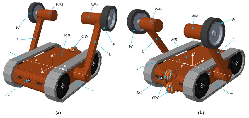
Machines 2021, 9, 10                                                                                              2 of 11

                       Handle by Boston Dynamics [20], which is a biped with two wheels at the end of the legs;
                       a similar concept has been adopted in the design of the Centauro quadruped, by IIT [21].
                       At a smaller scale, there are many examples of hybrid robots which combine legs, wheels,
                       and tracks in a simplified manner, with lower cost and consequently a wider range of
                       potential applications: the four possible combinations of L, W and T (LW, LT, WT, LWT) are
                       compared in [8] in terms of maximum speed, obstacle crossing capability, step/stair climb-
                       ing capability, walking capability of soft terrains and on uneven terrains, energy efficiency,
                       mechanical, and control complexity.
                             Considering locomotion solutions involving tracks (T, WT, LT, LWT), there are many
                       possible layouts. Robots can have non-articulated or articulated tracks with passive relative
                       mobility [22]; if the relative mobility of the articulated tracks is actuated to improve obstacle
                       crossing capability, they can be considered as LT hybrid robots. Another option is to link
                       tracked modules in series to compose snake-like climbing robots [23].
                             Focusing on LT hybrid robots, there are different ways to combine legs and tracks.
                       Besides the most obvious approach of using them in parallel [24–26], peripheral tracks can
                       be placed on the leg links [27]; this approach is also used for the Kylin robot, with LWT
                       hybrid locomotion [28].
                             When wheels are present and it is required to use them to increase speed and range
                       on even and compact grounds, they can be activated using many different systems. For ex-
                       ample, the contact of the wheels with the terrain can be enabled or disabled by the position
                       of the legs, as in the LWT Kylin robot.
                             Another possibility is to extract the wheels from the robot body to suspend the robot
                       on wheels. This solution has the benefit of enhancing the vehicle maneuverability, which is
                       a drawback of purely tracked robots; an example is the hybrid WT robot presented in [29].
                             In a previous study [30], a WT robot with two variable-shape tracks and four wheels
                       is proposed; the contact between wheels and terrain can be enabled or disabled by varying
                       the shape of the tracks.
                             The hybrid LWT Azimuth robot [31] is equipped with articulated legs with peripheral
                       tracks and wheels; depending on the leg position, wheels, legs, or tracks can be active.
                       The hybrid WT robot HELIOS-VI [32] has two tracks and two passive wheels placed at the
                       end of a rotating arm, which regulates the contact of the wheels with the terrain to reduce
                       the contact areas of the tracks, to improve maneuverability or to perform stair climbing
                       and descent.
                             In other cases, the tracks can be transformed into wheels changing their outer shape
                       by means of tensioning systems, exploiting the tracks elasticity [33,34]; the transformation
                       of tracks into wheels can also be achieved by adopting complex articulated supports for
                       the tracks [35].
                             This research is focused on the development of a hybrid LWT ground mobile robot for
                       surveillance and inspection, named WheTLHLoc (Wheel-Track-Leg Hybrid Locomotion).
                       Its locomotion system shows similarities with previously discussed robots, although the
                       proposed solution is new and has unique features with respect to other solutions presented
                       in scientific literature; similarities and differences will be highlighted in Section 2. The con-
                       sidered size is small (around 450 × 350 × 130 mm), since only cameras and environmental
                       sensors are to be carried and good maneuverability in restricted spaces is considered a
                       key feature of an inspection robot. Despite its limited dimensions, the combination of
                       all the three locomotion systems allows to perform wheeled locomotion with high speed,
                       energy efficiency, and range on flat and compact grounds, tracked locomotion on yielding
                       and soft terrains, and mixed use of rotating legs, wheels, and tracks to overcome steps,
                       stairs, and other obstacles.
                             The remaining of the paper is organized as follows: Section 2 discusses the conceptual
                       design and the main functional features of the WheTLHLoc robot; Section 3 illustrates
                       the maneuvers for stair climbing and descent, and the feasibility of the most critical
                       one (climbing) is verified by multibody simulation in Section 4; Section 5 presents the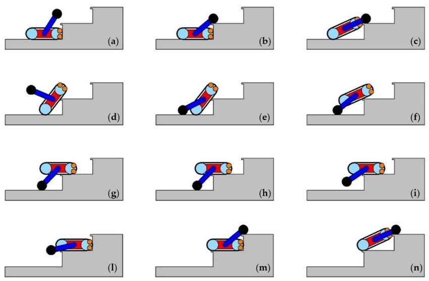
maneuvers for stair climbing and descent, and the feasibility of the most critical one
(climbing) is verified by multibody simulation in Section 4; Section 5 presents the embod-
iment design and the internal layout of the robot, and finally Section 6 outlines conclu-
sions and future work.
Machines 2021, 9, 10 3 of 11
2. Conceptual Design of the Hybrid Robot WheTLHLoc
The starting point of the conceptual design of the proposed hybrid locomotion robot
is the goal of combining tracks for soft and yielding terrains and wheeled locomotion on
embodiment design and the internal layout of the robot, and finally Section 6 outlines
flat and compact terrains. This combination can be obtained in different ways, as dis-
conclusions and future work.
cussed in the previous section. The proposed locomotion system (Figure 1) is in some
ways
2. similar toDesign
Conceptual the oneofofthe
HELIOS-VI [32], but
Hybrid Robot enhances its capabilities thanks to the fol-
WheTLHLoc
lowing design choices:
The starting point of the conceptual design of the proposed hybrid locomotion robot
• theInstead
is goal ofof a single short
combining tracks rotating
for softarmandplaced
yielding on terrains
the frontandof the vehicle,
wheeled it makes use
locomotion on
of two independently actuated rotating legs (Figure 1, L);
flat and compact terrains. This combination can be obtained in different ways, as discussed
• the
in The wheels section.
previous at the legTheendsproposed
(Figure 1,locomotion
W) are not passive, but independently
system (Figure 1) is in some actuated
ways
by to
similar gearmotors
the one of (Figure
HELIOS-VI 1, WM);[32], but enhances its capabilities thanks to the following
•
designThe common revolute axis of the two legs (Figure 1, A), is centered with respect to
choices:
• Instead ofbody,
the robot a singleandshort
the legs can perform
rotating arm placed complete
on the and
frontcontinuous rotations
of the vehicle, around
it makes use
it; two independently actuated rotating legs (Figure 1, L);
of
•• Twowheels
The omni wheels (Figure
at the leg ends 1, OW) are
(Figure placed
1, W) on passive,
are not the rear ofbutthe robot, so thatactuated
independently the con-
tactgearmotors
by of the tracks (Figure
(Figure 1, 1, T) with the terrain is avoided when the robot is supported
WM);
• on the
The two wheels
common andaxis
revolute on one of two
of the the omni wheels;1, A), is centered with respect to the
legs (Figure
• robot body, and the legs can perform complete and symmetric
The main robot body (Figure 1, MB) is externally continuouswith respect
rotations to theit;xy
around
• plane.
Two omni wheels (Figure 1, OW) are placed on the rear of the robot, so that the contact
of
The themain
tracks (Figure
camera is 1, T) with
placed on the
the terrain
front ofisthe
avoided
robot when
(Figurethe1,robot is supported
FC), but a secondaryon
the two wheels and on one of the omni wheels;
camera is placed on the rear (Figure 1, RC) since during step climbing (Section 3) and in
•otherThe main robot
scenarios body (Figure
it is necessary to move 1, MB) is externally
backwards; symmetric
additional with respect
environmental to the
sensors can
xy plane.
be placed inside the robot body, on the basis of the required tasks.
Figure
Figure 1. Conceptualdesign
1. Conceptual designofofthe
thehybrid
hybridleg-wheel-track
leg-wheel-track robot
robot Wheel-Track-Leg
Wheel-Track-Leg Hybrid
Hybrid Locomotion
Locomotion (WheTLHLoc):
(WheTLHLoc): (a)
(a) Front
Front view;
view; (b) rear
(b) rear viewview (W: Wheel;
(W: Wheel; L:T:Leg;
L: Leg; T: Track;
Track; MB:body;
MB: Main MainWM:
body; WM:gearmotor;
Wheel Wheel gearmotor;
OW: OmniOW: Omni
wheel; FC:wheel;
Front
camera;
FC: FrontRC: Rear camera;
camera; RC: RearA: Leg axis).
camera; A: Leg axis).
The main features
camera is ofplaced on the
this design arefront of the robot (Figure 1, FC), but a secondary
the following:
camera is placed on the rear (Figure 1, RC) since during step climbing (Section 3) and in
other scenarios it is necessary to move backwards; additional environmental sensors can
be placed inside the robot body, on the basis of the required tasks.
The main features of this design are the following:
i. It is possible to alternate wheeled locomotion on flat and compact terrains (Figure 2a)
and tracked locomotion on soft and yielding terrains (Figure 2b), both with differential
steering; the switch between the locomotion modes is commanded by the rotation of
the legs;
ii. The legs, longer than the arm of HELIOS-VI, can be used to overcome obstacles,
even performing differential steering, if required in case of asymmetrical obstacles;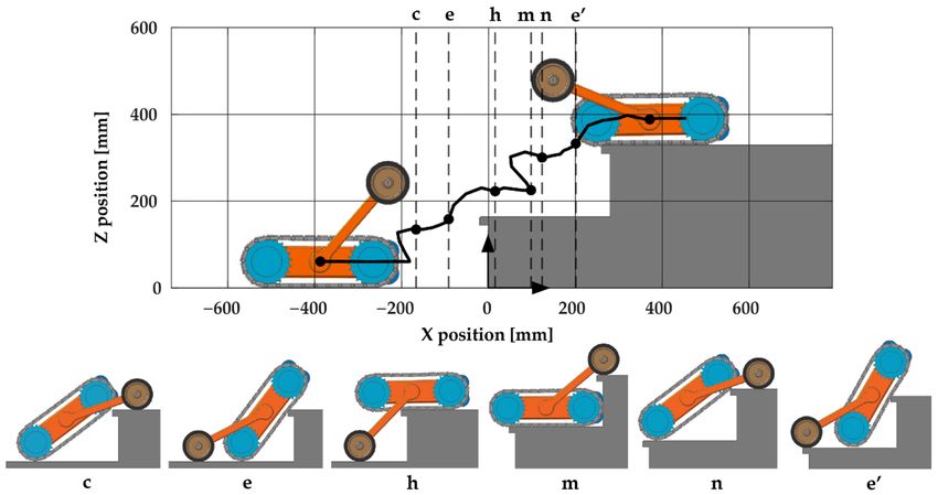
i. It is possible to alternate wheeled locomotion on flat and compact terrains (Figure 2a)
and tracked locomotion on soft and yielding terrains (Figure 2b), both with differen-
Machines 2021, 9, 10 tial steering; the switch between the locomotion modes is commanded by the rotation 4 of 11
of the legs;
ii. The legs, longer than the arm of HELIOS-VI, can be used to overcome obstacles, even
performing differential steering, if required in case of asymmetrical obstacles;
iii. iii. When
Whenthe therobot
robot isis in
in the
the wheeled
wheeled locomotion
locomotion (WL) (WL) position,
position, thethe field
field ofof view
view ofof the
the
front camera is optimally exploited
front camera is optimally exploited (Figure 2a); (Figure 2a);
iv. iv. Since
Sincethetherobot
robotmainmainbody body is symmetric
is symmetric withwith respect
respect to theto xy xy plane,
theplane, it is oper-
it is fully fully
operative even after an overturn; it is very unlikely that after a
ative even after an overturn; it is very unlikely that after a fall the robot remains on fall the robot remains
on one
one flank,
flank, andand eveneven in this
in this case
case a rotation
a rotation ofofthe
theleg
leginincontact
contactwith
with thethe terrain
terrain can
can
putagain
put again thethe robot
robot on on the
the tracks;
tracks;
v. v. The rotation of the legs
The rotation of the legs and the and the action
action ofof the
the wheels
wheels can can bebe used
used inin case
case ofof irregular
irregular
terrains and obstacles, i.e., when the use of only tracks is not
terrains and obstacles, i.e., when the use of only tracks is not sufficient to advance; sufficient to advance; in
in this
this case,
case, thethetwotwo legscan
legs canbebemoved
movedindependently
independentlyin in presence
presence of of asymmetric
asymmetric
groundirregularities
ground irregularities (Figure
(Figure 2c); 2c);
vi. vi. In particular, the combined motionofoflegs,
In particular, the combined motion wheels,
legs, wheels, and tracks
and cancan
tracks be used to overcome
be used to over-
steps and stairs, according to the sequences discussed
come steps and stairs, according to the sequences discussed in Section 3. in Section 3.
Figure 2. (a)
(a)Wheeled
Wheeledlocomotion
locomotionon onflat
flatand
andcompact surfaces;
compact (b)(b)
surfaces; tracked locomotion
tracked on yielding
locomotion terrains;
on yielding (c) hybrid
terrains; leg-
(c) hybrid
wheel-track locomotion
leg-wheel-track to overcome
locomotion obstacles.
to overcome obstacles.
previously mentioned, the proposed locomotion system presents similarities with
As previously
the one
the one of
of HELIOS-VI,
HELIOS-VI,though thoughititshows
showsthe thefollowing
followingdifferences:
differences: (i)(i) Independently
Independently ac-
actu-
tuated and longer legs, which can perform complete and
ated and longer legs, which can perform complete and continuous rotations in continuous rotations in case of
obstacle overcoming
obstacle overcoming and and stair climbing; (ii) actuated wheels to perform purely wheeled
locomotion with differential steering; (iii) capability of operating after an overturn, due to
the main
the main body
body symmetry.
symmetry.
Regarding the
Regarding thewheeled
wheeledlocomotion,
locomotion,there there are some
are some similarities with
similarities the the
with Kylin robot
Kylin [28]:
robot
Two actuated wheels are placed at the end of rotating arms, and passive
[28]: Two actuated wheels are placed at the end of rotating arms, and passive omni wheels omni wheels are
adopted. The advantages of the WheTLHLoc with respect to
are adopted. The advantages of the WheTLHLoc with respect to the Kylin are: (i) The the Kylin are: (i) The possi-
bility of using
possibility the longer
of using legs, also
the longer legs,inalso
combination with the
in combination with tracks, to overcome
the tracks, obstacles;
to overcome ob-
(ii) the capability of operating after an overturn due to the symmetry;
stacles; (ii) the capability of operating after an overturn due to the symmetry; (iii) the (iii) the most compact
most
and robust
compact and design.
robust design.
The capability of
The capability of operating
operatingafterafterand
andoverturn
overturnisisinincommon
commonwith with the
thehybrid
hybrid WT WTrobot
ro-
discussed in [29], but in comparison to this one, the following benefits
bot discussed in [29], but in comparison to this one, the following benefits of WheTLHLoc of WheTLHLoc can
be outlined:
can (i) The
be outlined: capability
(i) The of using
capability legs,legs,
of using wheels and and
wheels tracks in combination
tracks in combination to overcome
to over-
obstacles and climb stairs (Figure 2c); (ii) the polygon of the contact
come obstacles and climb stairs (Figure 2c); (ii) the polygon of the contact points points for the wheeled
for the
locomotion is much larger, allowing higher stability during turns, acceleration and breaking,
wheeled locomotion is much larger, allowing higher stability during turns, acceleration
and consequently higher motion performance.
and breaking, and consequently higher motion performance.
3. Step and Stair Climbing and Descent
3. Step and Stair Climbing and Descent
As already stated, the overall size of the robot is quite compact, since the considered
As already
payload stated, the
is represented by overall
cameras size
andof environmental
the robot is quite compact,
sensors for since the considered
surveillance and in-
payload is represented by cameras and environmental sensors for surveillance
spection. Moreover, a small robot can travel in narrow spaces that cannot be explored and in-
by
spection.
humans and Moreover,
is muchamore
smallportable.
robot canOntravel in narrow
the other hand, spaces that cannot
a drawback of smallberobots
explored by
is their
capability of facing stairs.
The climbing of steps and stairs can be performed according to the sequence rep-
resented in Figure 3 (frames a to m). In case of single steps, the sequence a–m is per-
formed once, while it is repeated n times in case of n steps.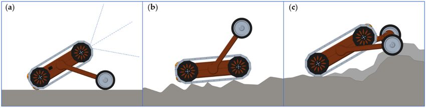
sary to switch direction.
Once the central zone of the tracks is in contact with the step edge (frame d), the legs
rotate backwards until they touch the ground behind the robot (frame e) and completely
lift the robot over the step (frames f to h); in this phase, both tracks and wheels rotate,
pushing the robot forward. Once the robot center of mass is sufficiently beyond the step
Machines 2021, 9, 10 5 of 11
edge, the robot moves forward on the tracks while the legs rotate forward (frame i–m) to
face the next step, if present, or to complete the task.
Figure 3. Stair-climbing sequence: the
Figure 3. Stair-climbing legs lift
sequence: theup theliftrobot
legs body
up the (a–c),
robot bodythen rotate
(a–c), then backward to complete
rotate backward to the step
complete
climbing (d–h); then thethe stepgoes
robot climbing (d–h);
forward then the
by tracks robot
(i–l) goesthe
to face forward by (m,n).
next step tracks (i–l) to face the next step
(m–n).
After approaching the step, the rotation of the legs lifts up the robot body (frames a–c);
The successful note
let us that the
execution robot,
of this whichisisnot
sequence not fully symmetric
assured in any dynamic with and
respect to the yz plane,
friction
must
condition, since theface the step
friction with and
of tracks the rear side,
wheels otherwise
with in the
the ground is following
necessary phase (frame d) it would
to complete
the maneuvernot be possible
in the to use the traction
phase corresponding to the of the tracks
frames d to g;due to the the
therefore, presence
motionofstrat-
the omni wheels.
Therefore,
egy must be planned andif verified
the robotbyapproaches the stairor
analytical approach moving forward,
numerically. a 180◦ 4,
In Section pivoting
the must be
performed by differential steering before
multibody simulation of the stair climbing maneuver is discussed.climbing the first step, imposing an equal speed
to the two tracks with opposite directions. This maneuver
The stair descent can be executed inverting the stair climbing sequence, as shown in can be used whenever it is
necessary to switch direction.
Figure 4. In the descent, the successful execution of the maneuver is less critical, since it is
Once the the
not necessary to overcome central zoneforce
gravity of the
bytracks
meansisofinthe
contact with
traction ofthe step and
wheels edgetracks.
(frame d), the legs
rotate backwards until they touch the ground behind the robot (frame e) and completely lift
the robot over the step (frames f to h); in this phase, both tracks and wheels rotate, pushing
the robot forward. Once the robot center of mass is sufficiently beyond the step edge,
the robot moves forward on the tracks while the legs rotate forward (frame i–m) to face the
next step, if present, or to complete the task.
The successful execution of this sequence is not assured in any dynamic and friction
condition, since the friction of tracks and wheels with the ground is necessary to complete
the maneuver in the phase corresponding to the frames d to g; therefore, the motion
strategy must be planned and verified by analytical approach or numerically. In Section 4,
the multibody simulation of the stair climbing maneuver is discussed.
The stair descent can be executed inverting the stair climbing sequence, as shown in
Figure 4. In the descent, the successful execution of the maneuver is less critical, since it is
not necessary to overcome the gravity force by means of the traction of wheels and tracks.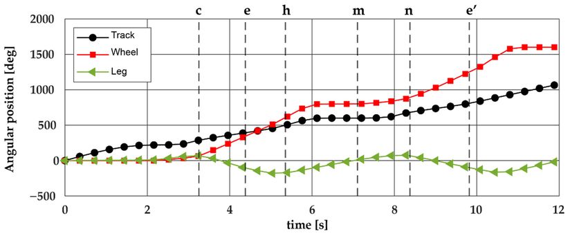
hines 2021, 9, x FOR PEER REVIEW 6 of 11
es 2021, 9, xMachines
FOR PEER2021, 9, 10
REVIEW 6 of 11 6 of 11
Figure 4. Stair-descent sequence: the robot approaches the descent by tracks (a–b) and uses the
legs to come
Figure 4. Stair-descent downthe
sequence: gradually without shocks
robot approaches until by
the descent thetracks
tracks(a,b)
touch theuses
and nextthe
step (c–f); thendown
the gradually
Figure
legs 4. Stair-descent
rotate backwardssequence: the robot
(g) to complete theapproaches
step descentthe(h–i).
descent by tracks (a–b)legs
andtouses
comethe
without shocks
legsuntil the tracks
to come downtouch the next
gradually step (c–f);
without shocksthen thethe
until legstracks
rotatetouch
backwards (g)step
the next to complete thethe
(c–f); then step descent (h,i).
legs4.rotate backwards
Multibody (g) to complete
Simulation theClimbing
of Stair step descent (h–i).
4. Multibody Simulation of Stair Climbing
The feasibility
Theoffeasibility
4. Multibody Simulation theofstair
Stairclimbing
ofClimbing maneuver
the stair climbingdiscussed
maneuverindiscussed
Section 3 in has been checked
Section 3 has been checked
with a dynamic model
with ofa dynamicimplemented in
model implementedRecurdyn, a multibody
in Recurdyn, software
a multibody commonly
software used
commonly used
The feasibility the stair climbing maneuver discussed in Section 3 has been checked
to simulate to
complex
simulate mechanical
complex systems
mechanical involving
systems a large number
involving a of
large components
number ofand to
components and
with a dynamic model implemented in Recurdyn, a multibody software commonly used
perform efficient contact analysis by means of penalty algorithms [36]. In particular,
to perform efficient contact analysis by means of penalty algorithms [36]. In particular, these
to simulate complex mechanical systems involving a large number of components and to
features canthese
be exploited
features tocansimulate the complex
be exploited to simulatedynamic behavior
the complex of a tracked
dynamic system,
behavior of a tracked sys-
perform efficient contact analysis by means of penalty algorithms [36]. In particular, these
composed of a high
tem, numberofofa bodies
composed (sprockets,
high number track (sprockets,
of bodies links, and rollers) in contact
track links, with in contact
and rollers)
features can be exploited to simulate the complex dynamic behavior of a tracked system,
each other and
withwith
eachthe ground
other and within configurations,
the ground in which are highly
configurations, variable
which duringvariable
are highly the during
composed of a high number of bodies (sprockets, track links, and rollers) in contact with
vehicle motion [37]. motion [37].
the vehicle
each other and with the ground in configurations, which are highly variable during the
Figures 5–7 Figures
represent simulation
5–7 representresults related
simulation to a stair
results withto
related 300 mm of
a stair run300
with andmm 160 of run and
vehicle motion [37].
mm of rise 160
(standard
mm of risesize (standard
for buildings).
size forFigure 5 shows
buildings). the 5angular
Figure shows the position vs. position
angular time vs. time
Figures 5–7 represent simulation results related to a stair with 300 mm of run and 160
graph for wheels
graph(red), tracks (red),
for wheels (black)tracks
and legs (green).
(black) and These motion laws
legs (green). Thesehave beenlaws
motion de- have been
mm of rise (standard size for buildings). Figure 5 shows the angular position vs. time
signed to realize the climbing
designed to realize sequence of Figure
the climbing 3 and are
sequence imposed
of Figure to the
3 and areactuators
imposedintothe the actuators
graph for wheels (red), tracks (black) and legs (green). These motion laws have been de-
simulation. in
Thethelaws are characterized
simulation. The laws by areconstant speedby
characterized phases andspeed
constant stop phases.
phases Since
and stop phases.
signed to realize the climbing sequence of Figure 3 and are imposed to the actuators in the
Since
instantaneous instantaneous
speed variations are speednotvariations are not
feasible (they wouldfeasible (they
require wouldacceleration),
infinite require infinite accelera-
simulation. The lawsconstant
tion), are characterized
speed by constant
phases and stop speed
phases phases
have and linked
been stop phases.
by Since
cubic splines to obtain
constant speed phases and stop phases have been linked by cubic splines to obtain twice
instantaneous twice
speedcontinuously
variations aredifferentiable
not feasible (they
motion would require
laws without infinite acceleration),
acceleration peaks.
continuously differentiable motion laws without acceleration peaks.
constant speed phases and stop phases have been linked by cubic splines to obtain twice
continuously differentiable motion laws without acceleration peaks.
Figure 5. Motion laws5.of
Figure tracks,laws
Motion wheels, and legs
of tracks, (angular
wheels, positions
and legs vs.positions
(angular time) imposed in imposed
vs. time) the multibody
in the simulation to
realize the stairmultibody simulation
climbing sequence of to realize
Figure the stair
3; stop climbing
phases sequence
and constant of Figure
speed phases3;are
stop phases
linked byand
cubicconstant
splines to avoid
Figure
speed5. phases
Motionare
laws of tracks,
linked wheels,
by cubic andtolegs
splines (angular
avoid positions
acceleration vs. time) imposed in the
peaks.
acceleration peaks.
multibody simulation to realize the stair climbing sequence of Figure 3; stop phases and constant
speed phases are linked by cubic splines to avoid acceleration peaks.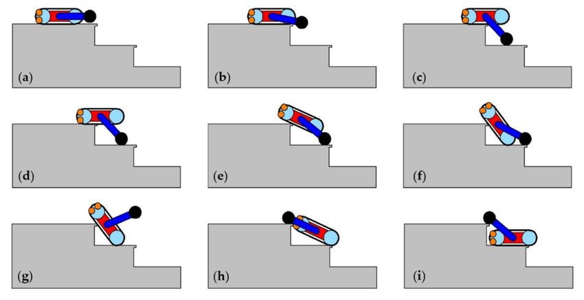
nes 2021, 9, x FOR PEER REVIEW 7 of 11
Machines 2021, 9, 10 7 of 11
s 2021, 9, x FOR PEER REVIEW 7 of 11
Figure 6. Multibody simulation results of the stair climbing sequence of Figure 3: Horizontal (x)
and vertical (z) displacements of the reference frame origin of the robot main body (Figure 1) and
pitch angle θ of the robot main body.
Figure 6 represents the horizontal and vertical displacements of the robot reference
Figure
frame6. origin
Figure 6. Multibody Multibody
simulation simulation
results
(Figure results
of the
1) with stairof the
to stair
climbing
respect climbing
sequence
a fixed ofsequence
reference Figure 3:ofHorizontal
frame Figure
located3: at
Horizontal
(x) and
the (x)edge
vertical
lower (z) displace-
and
ments of the of vertical
reference (z)
frame
the first displacements
steporigin of the
(Figure of the
7), robot reference
mainwith
together frame
bodythe origin
(Figure of
robot1)pitch the
and pitch robot
angle main
angle body (Figure 1) and
θ. θ of the robot main body.
pitch angle θ of the robot main body.
Figure 6 represents the horizontal and vertical displacements of the robot reference
frame origin (Figure 1) with respect to a fixed reference frame located at the lower edge
of the first step (Figure 7), together with the robot pitch angle θ.
Figure 7. Multibody
Figure 7.simulation
Multibody results of the results
simulation stair climbing sequence
of the stair of Figure
climbing 3: Trajectory
sequence of Figureof3:reference frame
Trajectory of origin of the
reference
robot main body frame
(Figure 1). origin of the robot main body (Figure 1).
Figure 7 shows Figure 6 represents
the trajectory of thetherobot
horizontal
body frameand vertical displacements
origin with respect to theof the robot reference
fixed
reference frame frame
andorigin (Figure 1)positions
six significant with respect of theto climbing
a fixed reference
process:frame
c, e, h,located at the
m, n, e’. Thelower edge of
Figure 7. Multibody
symbols the simulation
of such first
six positionsresults
step (Figure of
7),the
correspond stairtoclimbing
together with
the sequence
the
frame robot of Figure
pitch
symbols the3: stair
ofangle Trajectory
θ. climbingof se-
reference
quence frame origin
of Figure of theposition
3.Figure
The robot main
7 shows e’thebody
is (Figure
trajectory
similar to e1).
ofafter
the climbing
robot body frame
one step,origin
so thewith
cyclerespect
e–h– to the fixed
m–n–e’ can be repeated to climb all the stair. The time values corresponding to these c,
reference frame and six significant positions of the climbing process: sixe, h, m, n, e’.
Figure 7 shows the trajectory of six
thepositions
robot body frame origin with respect to the of
fixed
positions are marked in the graphs of Figures 5 and 6. The simulations have validated thestair climbing
The symbols of such correspond to the frame symbols the
reference framesequence
and six significant
of Figure positions
3. The of thee’climbing
position process: c, e,climbing
h, m, n, e’.
oneThe
feasibility of the maneuver and can be used to tune is thesimilar to estrategy
climbing after as a function step,
of so the cycle
symbols of such six positions
e–h–m–n–e’ can correspond
be repeated totothe frame
climb all symbols
the stair. of the
The timestair climbing
values se-
corresponding to these
the step geometry.
quence of Figure 3. The position e’ is similar to e after climbing one step, so the
six positions are marked in the graphs of Figures 5 and 6. The simulations have validated cycle e–h–
m–n–e’ can be
5. Internal repeatedand to
the feasibility
Layout climb
of the
Embodimentallmaneuver
theDesign
stair. and
The cantimebevalues corresponding
used to tune the climbing to these six as a function
strategy
positions are marked in the graphs
of the step geometry. of Figures 5 and 6. The simulations have validated the
In this section, the embodiment design of the robot is discussed. Figure 8 shows the
feasibility of the maneuver and can be used to tune the climbing strategy as a function of
internal layout 5. of the robot
Internal body;and
Layout theEmbodiment
labels of the main Design components are listed in Table 1.
the step geometry.
In this section, the embodiment design of the robot is discussed. Figure 8 shows the
5. Internal Layout and Embodiment
internal layout of the robotDesign body; the labels of the main components are listed in Table 1.
In this section, the embodiment design of the robot is discussed. Figure 8 shows the
internal layout of the robot body; the labels of the main components are listed in Table 1.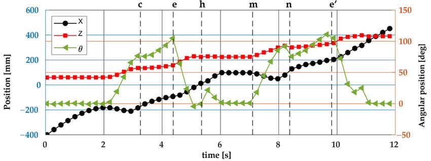
nes 2021, 9, Machines 9, 10
2021,REVIEW
x FOR PEER 8 of 11 8 of 11
Figurelayout
Figure 8. Internal 8. Internal
of thelayout
robot:of(a)
the robot: of
Section (a)the
Section
mainofbody
the main
alongbody along
the xz the(b)
plane; xz upper
plane; view
(b) upper
(see the list of the
view (see the
main components in Table 1). list of the main components in Table 1).
Main robot
Table 1. plates
The upper and lower internal (UP components.
and LP) constitute the structural frame of
the robot, on which the supports of the transmission components (gearmotors, axes, bear-
Component Symbol in Figure 8 Characteristics
ings, and gears of tracks and wheels) are fixed. The plates support also the other devices
Outer Case OC 3D printed kevlar-reinforced nylon
hosted in the robot body: Controller, battery, PWM drives, and video cameras. Free space
Upper structural plate UP 3D printed micro-carbon-fiber-filled nylon
is available
Lower structural plate in the front and rear
LP sides to place additional components (e.g., environmental
3D printed micro-carbon-fiber-filled nylon
sensors,
Leg gearmotor extra batteries) based
LM on the required robot task. The structural components
Micromotors RH-158-2s-12V, 26 rpm
(plates and supports) are 3DTM
Track gearmotor printed in micro carbon fiber filled nylon,
Micromotors while the33
RH-158-2s-12V, upper
rpm
Wheel gearmotor WM EMG 30, 12v, 170
and lower external cases are 3D printed in Kevlar-reinforced nylon for higher impact re- rpm
Motor driver (PWM)
sistance. PD L298N Dual H-Bridge motor controller
Leg axis LA Stainless steel tube (∅10 mm, 1 mm wall)
Track axis TA High carbon steel tube (C45, ∅6 mm)
Table 1. Main robot components.
Leg gear LG 20:14, M2
Track gear Component TG
Symbol in Figure 8 18:12,
Characteristics M1.5
Omni wheels group
Outer Case OW OC 3D printed kevlar-reinforced mm
Rotacaster 95A-50 nylon
Controller C National Instruments MyRio 1900
Upper structural plate UP 3D printed micro-carbon-fiber-filled nylon
Battery B HRB 50C-4S-RC-LiPo, 14.8V, 2200 mAh
Lower structural plate LP 3D printed micro-carbon-fiber-filled nylon
Front camera FC Yosoo OV7670-300KP-VGA
Rear cameraLeg gearmotor RC LM Micromotors
Yosoo RH-158-2s-12V,
OV7670-300KP-VGA26 rpm
Slip ring Track gearmotor SR TM Micromotors RH-158-2s-12V,
12 mm-12wires miniature 33slip
rpmring
Wheel gearmotor WM EMG 30, 12v, 170 rpm
Motor driver (PWM) PD internal plates
The upper and lower L298N(UPDualandH-Bridge motor controller
LP) constitute the structural frame of
Leg axis LA Stainless steel tube (∅10
the robot, on which the supports of the transmission components mm, 1 mm wall)
(gearmotors, axes, bear-
Track ings,
axis and gears of tracks
TA and wheels) High carbon steel tube (C45, ∅6 mm)
are fixed. The plates support also the other devices
Leg gear LG Controller, battery, PWM20:14,
hosted in the robot body: M2and video cameras. Free space
drives,
Track gear TG 18:12, M1.5
is available in the front and rear sides to place additional components (e.g., environmen-
Omni wheels group OW Rotacaster 95A-50 mm
tal sensors, extra batteries) based on the required robot task. The structural components
Controller C National Instruments MyRio 1900
(plates and supports) are 3D printed in micro carbon fiber filled nylon, while the upper and
Battery B HRB 50C-4S-RC-LiPo, 14.8V, 2200 mAh
lower external cases are 3D printed in Kevlar-reinforced nylon for higher impact resistance.
Front camera FC Yosoo OV7670-300KP-VGA
The wheel gearmotors (Figure 8, WM) are directly connected to the wheels, and the
Rear camera RC Yosoo OV7670-300KP-VGA
necessary power supply and encoder signals are transmitted by slip rings (Figure 8, SR),
Slip ring SR 12 mm-12wires miniature slip ring
allowing continuous rotation, if necessary. The MyRio-1900 board by National Instruments
(USA) has been selected as the control system, since it can properly manage the motion
The wheel gearmotors (Figure 8, WM) are directly connected to the wheels, and the
control of the six axes with encoders (two legs, two tracks, and two wheels), the video
necessary power supply and encoder signals are transmitted by slip rings (Figure 8, SR),Machines 2021, 9, 10 9 of 11
camera signals, and the WiFi connection with a host computer; moreover, it is equipped
with a three-axis accelerometer to acquire data regarding the robot motion, and can manage
an Inertial Measurement Unit.
6. Conclusions and Future Work
In this paper, the conceptual design of a novel small-scale leg-wheel-track hybrid
locomotion robot, named WheTLHLoc, is presented. A comparison with respect to other
hybrid mobile robots is outlined in Section 2, highlighting similarities and differences.
The mechanical architecture of WheTLHLoc has been designed to combine the advantages
of tracked locomotion on soft and yielding terrains and the ones of wheeled locomotion on
flat and compact grounds. The switch between these two modes is realized by means of
rotating legs carrying driving wheels. The robot is capable of performing step and stair
climbing and descent by moving in proper combination legs, wheels, and tracks.
The effectiveness of the climbing maneuver is not obvious due to the limited dimension
of the robot with respect to step height. Therefore, the feasibility has been verified by
numerical simulation using the multibody software Recurdyn. Variations of this maneuver
can be used to overcome obstacles with different shape, not squared, using the same
principle of lifting the side of the robot close to the obstacle by the legs, then advance using
the tracks, and finally completing the robot lifting by rotating backwards the legs.
The detailed embodiment design has been completed, as discussed in Section 5. In the
following of the research, the first prototype of the robot will be realized for an experimental
validation of the proposed hybrid locomotion system and its test in real surveillance and
inspection tasks.
Author Contributions: L.B. conceived the locomotion system and the robot architecture; L.B., S.E.N.,
P.B., and M.B. developed the detailed embodiment design; P.F. supervised the scientific methodology
for the functional design and the multibody simulations; M.B. performed the multibody simulations;
all authors have prepared the manuscript. All authors have read and agreed to the published version
of the manuscript.
Funding: This research received no external funding.
Institutional Review Board Statement: Not applicable.
Informed Consent Statement: Not applicable.
Data Availability Statement: Data sharing not applicable. No new data were created or analyzed in
this study. Data sharing is not applicable to this article.
Conflicts of Interest: The authors declare no conflict of interest.
References
1. IFR International Federation of Robotics, World Robotics 2019, Industrial Robots and Service Robots. Available online: https:
//www.ifr.org (accessed on 1 September 2020).
2. Quaglia, G.; Visconte, C.; Scimmi, L.S.; Melchiorre, M.; Cavallone, P.; Pastorelli, S. Design of a UGV powered by solar energy for
precision agriculture. Robotics 2020, 9, 13. [CrossRef]
3. Mateo Sanguino, T.J. 50 years of rovers for planetary exploration: A retrospective review for future directions. Robot. Auton. Syst.
2017, 94, 172–185. [CrossRef]
4. Murphy, R.R. Rescue robotics for homeland security. Commun. ACM 2004, 47, 66–68. [CrossRef]
5. Chun, W.H.; Papanikolopoulos, N. Robot Surveillance and Security. In Springer Handbook of Robotics; Siciliano, B., Khatib, O., Eds.;
Springer: Berlin/Heidelberg, Germany, 2016; pp. 1605–1626.
6. Tadokoro, S. Rescue Robotics. DDT Project on Robots and Systems for Urban Search and Rescue; Springer: London, UK, 2009.
7. Dubey, S. Robot Locomotion—A Review. Int. J. Appl. Eng. Res. 2015, 10, 7357–7369.
8. Bruzzone, L.; Quaglia, G. Review article: Locomotion systems for ground mobile robots in unstructured environments. Mech. Sci.
2012, 3, 49–62. [CrossRef]
9. Kececi, E.F.; Ceccarelli, M. Mobile Robots for Dynamic Environments; ASME Press: New York, NY, USA, 2015; ISBN 978-0791860526.
10. Chung, W.; Iagnemma, K. Wheeled robots. In Springer Handbook of Robotics; Siciliano, B., Khatib, O., Eds.; Springer:
Berlin/Heidelberg, Germany, 2016; pp. 575–594.Machines 2021, 9, 10 10 of 11
11. Kim, J.; Kim, J.; Lee, D. Mobile robot with passively articulated driving tracks for high terrainability and maneuverability on
unstructured rough terrain: Design, analysis, and performance evaluation. J. Mech. Sci. Technol. 2018, 32, 5389–5400. [CrossRef]
12. Ottonello, G.; Berselli, G.; Bruzzone, L.; Fanghella, P. Functional Design of Elloboat, a Tracked Vehicle for Launching and Beaching
of Watercrafts and Small Boats. In Proceedings of the 14th IEEE/ASME International Conference on Mechatronic and Embedded
Systems and Applications MESA 2018, Oulu, Finland, 2–4 July 2018. [CrossRef]
13. Bruzzone, L.; Berselli, G.; Bilancia, P.; Fanghella, P. Design Issues for Tracked Boat Transporter Vehicles. In Advances in Mechanism
and Machine Science. IFToMM WC 2019. Mechanisms and Machine Science; Springer: Cham, Switzerland, 2019; Volume 73,
pp. 3671–3679. [CrossRef]
14. Vukobratovic, M.; Borovac, B. Zero-moment point-thirty five years of its life. Int. J. Hum. Robot. 2004, 1, 157–173. [CrossRef]
15. Manchester, I.R.; Mettin, U.; Iida, F.; Tedrake, R. Stable dynamic walking over uneven terrain. Int. J. Robot. Res. 2011, 30, 265–279.
[CrossRef]
16. Altendorfer, R.; Moore, N.; Komsuoglu, H.; Buehler, M.; Brown, H.B., Jr.; McMordie, D.; Saranli, U.; Full, R.; Koditschek, D.E.
RHex: A biologically inspired hexapod runner. Auton. Robot. 2001, 11, 207–213. [CrossRef]
17. Bruzzone, L.; Fanghella, P. Functional Redesign of Mantis 2.0, a Hybrid Leg-Wheel Robot for Surveillance and Inspection.
J. Intell. Robot. Syst. Theory Appl. 2016, 81, 215–230. [CrossRef]
18. Quaglia, G.; Bruzzone, L.; Oderio, R.; Razzoli, R.P. EPI.Q mobile robots family. In Proceedings of the ASME 2011 International Me-
chanical Engineering Congress and Exposition, IMECE 2011, Denver, CO, USA, 11–17 November 2011; Volume 7, pp. 1165–1172.
[CrossRef]
19. Quaglia, G.; Butera, L.G.; Chiapello, E.; Bruzzone, L. UGV epi.q-mod. In Advances on Theory and Practice of Robots and Manipulators;
ROMANSY 2014. Mechanisms and Machine Science; Springer: Cham, Switzerland, 2014; Volume 22, pp. 331–339. [CrossRef]
20. Boston Dynamics, Handle. Available online: https://www.bostondynamics.com/handle (accessed on 1 September 2020).
21. Kashiri, N.; Baccelliere, L.; Muratore, L.; Laurenzi, A.; Ren, Z.; Hoffman, E.M.; Kamedula, M.; Rigano, G.F.; Malzahn, J.;
Cordasco, S.; et al. CENTAURO: A hybrid locomotion and high power resilient manipulation platform. IEEE Robot. Autom. Lett.
2019, 4, 1595–1602. [CrossRef]
22. Hirose, S.; Shirasu, T.; Fukushima, E.F. Proposal for cooperative robot Gunryu composed of autonomous segments.
Robot. Auton. Syst. 1996, 17, 107–118. [CrossRef]
23. Lee, G.; Kim, H.; Seo, K.; Kim, J.; Sitti, M.; Seo, T.W. Series of multilinked caterpillar track-type climbing robots. J. Field Robot.
2016, 33, 737–750. [CrossRef]
24. Fujita, T.; Sasaki, T. Development of hexapod tracked mobile robot and its hybrid locomotion with object-carrying. In Proceedings
of the 5th IEEE International Symposium on Robotics and Intelligent Sensors, IRIS 2017, Ottawa, ON, Canada, 5–7 October 2017;
pp. 69–73. [CrossRef]
25. Babu, N.; Sujatha, S.; Narayanan, S.; Balamurugan, V. Novel Hybrid Leg-Track Locomotion Robot and its Stability Analysis Using
a Unified Methodology. Procedia Comput. Sci. 2018, 133, 486–493. [CrossRef]
26. Rea, P.; Ottaviano, E. Design and development of an inspection robotic system for indoor applications. Robot. Comput. Integr. Manuf.
2018, 49, 143–151. [CrossRef]
27. Hirose, S.; Fukuda, Y.; Yoneda, K.; Nagakubo, A.; Tsukagoshi, H.; Arikawa, K.; Endo, G.; Doi, T.; Hodoshima, R. Quadruped
walking robots at Tokyo Institute of Technology. IEEE Robot. Autom. Mag. 2009, 16, 104–114. [CrossRef]
28. Han, C.; Xu, Y.; Xu, X.; Zeng, Z.; Lu, H.; Zhou, Z. Remote control and autonomous driving: The system-wide design of a
wheel-track transformable robot—Kylin Blaster. In Proceedings of the 2018 Chinese Automation Congress (CAC), Xi’an, China,
23–25 November 2018; pp. 3446–3451. [CrossRef]
29. Ben-Tzvi, P.; Saab, W. A hybrid tracked-wheeled multi-directional mobile robot, ASME. J. Mech. Robot. 2019, 11, 041008. [CrossRef]
30. Kim, J.; Kim, Y.G.; Kwak, J.H.; Hong, D.H.; An, J. Wheel & track hybrid robot platform for optimal navigation in an urban
environment. In Proceedings of the SICE Annual Conference, Taipei, Taiwan, 18–21 August 2010; pp. 881–884.
31. Michaud, F.; Letourneau, D.; Arsenault, M.; Bergeron, Y.; Cadrin, R.; Gagnon, F.; Legault, M.A.; Millette, M.; Pare, J.F.;
Remblay, M.C.; et al. Multi-modal locomotion robotic platform using leg-track-wheel articulations. Auton. Robot. 2005, 18, 137–
156. [CrossRef]
32. Hirose, S.; Fukushima, E.; Damoto, R.; Nakamoto, H. Design of terrain adaptive versatile crawler vehicle HELIOS-VI. In Pro-
ceedings of the IEEE International Conference on Intelligent Robots and Systems, Maui, HI, USA, 29 October–3 November 2001;
pp. 1540–1545. [CrossRef]
33. Luo, Z.; Shang, J.; Wei, G.; Ren, L. A reconfigurable hybrid wheel-track mobile robot based on Watt II six-bar linkage.
Mech. Mach. Theory 2018, 128, 16–32. [CrossRef]
34. Gao, X.; Cui, D.; Guo, W.; Mu, Y.; Li, B. Dynamics and stability analysis on stairs climbing of wheel-track mobile robot.
Int. J. Adv. Robot. Syst. 2017, 14, 1–13. [CrossRef]
35. Zhou, F.; Xu, X.; Xu, H.; Zhang, X. A multimodal hybrid robot with transformable wheels. In Proceedings of the 2017 IEEE
International Conference on Real-Time Computing and Robotics, RCAR 2017, Okinawa, Japan, 14–18 July 2017; pp. 139–144.
[CrossRef]Machines 2021, 9, 10 11 of 11
36. Bilancia, P.; Berselli, G.; Bruzzone, L.; Fanghella, P. A practical method for determining the pseudo-rigid-body parameters of
spatial compliant mechanisms via CAE tools. Procedia Manuf. 2017, 11, 1709–1717. [CrossRef]
37. Mo, H.; Jianzhong, S.; Zirong, L.; Zhuo, W. Trench-crossing capability analysis of a reconfigurable tracked mobile robot.
In Proceedings of the International Conference on Intelligent Robotics and Applications, Shanghai, China, 10–12 November 2010;
pp. 509–518. [CrossRef]You can also read