Pterodactyl: Development and Comparison of Control Architectures for a Mechanically Deployed Entry Vehicle
←
→
Page content transcription
If your browser does not render page correctly, please read the page content below

Pterodactyl: Development and Comparison of Control
  Architectures for a Mechanically Deployed Entry
                       Vehicle
                   Wendy A. Okolo∗, Benjamin W. Margolis†, Sarah N. D’Souza‡
                        NASA Ames Research Center, Moffett Field, CA 94035, USA

                                               Jeffrey D. Barton§
                  John Hopkins University Applied Physics Laboratory, Laurel, MD, 20723

                                                    Abstract
    The Pterodactyl project, seeks to advance the current state-of-the-art for entry vehicles by developing
novel guidance and control technologies for Deployable Entry Vehicles (DEVs) that can be applied to various
entry vehicle configurations. This paper details the efforts on the NASA-funded Pterodactyl project to in-
vestigate and implement multiple control techniques for an asymmetric mechanical DEV. We design multiple
control architectures for a Pterodactyl Baseline Vehicle (PBV) and evaluate their performance in achieving
varying guidance commands during entry. The control architectures studied are (i) propulsive control sys-
tems such as reaction control systems and (ii) non-propulsive control systems such as aerodynamic control
surfaces and internal moving masses. For each system, state-feedback integral controllers based on linear
quadratic regulator (LQR) optimal control methods are designed to track guidance commands of either (i)
bank angle or (ii) angle of attack and sideslip angle as determined by the desired guidance trajectory. All
control systems are compared for a lunar return reference mission and by providing a comparative analysis of
these systems, configurations, and performance, the efforts detailed in this paper and the Pterodactyl project
as a whole will help entry vehicle system designers determine suitable control architectures for integration
with DEVs and other entry vehicle types.

                                               I.   Introduction
    Pterodactyl is a NASA-funded design and test capability to (i) advance the current state of the art for
entry vehicle guidance and control (G&C) and (ii) determine the feasibility of control system integration for
various entry vehicle types. A deployable Entry Vehicles (DEV) is a type of unconventional entry vehicle
that demonstrates significant promise for enabling new missions including sample return missions and high-
mass payload delivery. Because they have no back shell, a DEV can stow into a smaller volume for launch
and deploy prior to entry. This novelty in their design, results in challenges in developing and integrating
feasible guidance and control solutions for entry, descent, and landing. Thus, the Pterodactyl capability,
driven and funded by NASA’s Space Technology Mission Directorate (STMD) is being utilized to develop
novel hardware and software G&C solutions for DEVs that will enable their use in existing and future space
missions as demonstrated for a sample return mission in this paper [1].
    To advance the state of the art for entry vehicle guidance and control, the Pterodactyl project is (i)
designing and integrating unconventional control hardware architectures onto a DEV and (ii) developing
and applying novel guidance and control algorithms for the vehicle to utilize the control hardware designs
in flight [1]. The current state of the art for entry vehicle control hardware utilizes reaction control systems
  ∗ Aerospace  Research Engineer, Intelligent Systems Division, MS 269-1, AIAA Member
  † Graduate  Pathways Student, Systems Analysis Office, MS 258-1, AIAA Member
  ‡ Principal Investigator, Systems Analysis Office, MS 258-1, AIAA Member
  § Guidance & Control Engineer, Force Projection Sector, JHU/APL, Non-Member

                                                        1 of 14

                                  American Institute of Aeronautics and Astronautics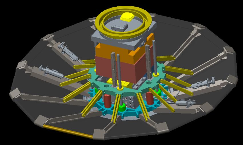
(RCS) for rigid entry vehicles such as the Mars Science Laboratory (MSL), Apollo capsule, and the Space
Shuttle [2]. These reaction control systems consist of a set of thrusters mounted on the backshells of the rigid
vehicles to steer them during entry. Since DEVs have no backshell, mounting RCS thrusters is a non-trivial
hardware integration challenge. Thus, the Pterodactyl effort is investigating the feasibility of integrating
not just RCS on a DEV, but unconventional control architectures such as (i) moving masses to control the
vehicle by changing it’s center of gravity (CG) and inertia and (ii) aerodynamic control effectors to control
the vehicle by generating aerodynamic moments. These two techniques, untraditional for entry vehicles,
have been demonstrated in other aerospace vehicle applications such as in aircraft formation flight for fuel
savings in which Okolo et al [3] utilized internal fuel transfer to generate roll moments to trim an aircraft by
changing it’s CG and inertia matrix. Furthermore, aerodynamic control surfaces such as elevators, ailerons,
and rudders, are routinely used to generate pitch, roll, and yaw aerodynamic moments, respectively, to trim
and steer aircraft. Single flap designs have also been demonstrated for entry vehicle systems such as the Mid
L/D vehicle [4] for which control surfaces and reaction control systems were utilized to generate moments.
    In terms of the software solutions being developed by Pterodactyl, it is important to understand the
traditional guidance and control algorithms utilized by heritage entry vehicles. Heritage entry vehicles utilize
a bank-angle guidance scheme to modulate the lift vector and control the downrange and crossrange errors in
a coupled fashion, while relying on the vehicle’s natural trim angle of attack based on the vehicle’s center of
gravity (CG) location at launch. Mitigating these downrange and cross-range errors and guiding the vehicle
along a trajectory during entry with limited tuning knobs can be a challenge for the guidance system as it
has to determine when to change the bank angle and thus lift vector to reduce these errors [1]. Conducting
these bank reversals introduces errors due to rate and acceleration limits of the control system effecting
these guidance commands. Pterodactyl has developed a guidance capability that uncouples longitudinal and
lateral/directional forces allowing for independent downrange and crossrange guidance commands through
direct angle of attack modulation for downrange control and sideslip modulation for cross-range control [5].
This provides G&C solutions that can allow for traditional bank angle or uncoupled angle of attack and
sideslip guidance commands to be followed by a control system.
    Furthermore, heritage entry vehicles have typically used classical control methods such as proportional-
integral-derivative (PID) controllers and other variants to achieve guidance commands [6, 7]. The design
process using these classical techniques involves analyzing the stability of the vehicle and designing a con-
troller that can (i) stabilize the vehicle by moving the poles of the system to the left-hand side of the
imaginary plane and (ii) control the vehicle to follow commands by determining a suitable control gain that
will drive the errors between the commanded and true signals to zero. These methods provide good stability
characteristics and do not have high computational requirements but require linear time invariant (LTI)
system dynamics and do not provide a platform to achieve optimal predefined objectives such as minimal
control effort over an entire trajectory. Thus, the Pterodactyl controls approach is to utilize optimal modern
control methods, specifically linear quadratic regulator (LQR) control design for each unconventional hard-
ware architecture presented in this paper. This provides the capability to develop a robust controller that
stabilizes and controls the vehicle in an optimal fashion while balancing pre-defined control effort usage and
vehicle performance requirements. The analysis and evaluation of the control designs form the brunt of the
work presented in this paper.
    First, we give an overview of the reference re-entry mission, the baseline vehicle, and the three control
hardware architectures in Section II. In Section III, we describe the integrated Python simulation environment
developed to simulate the vehicle and evaluate the controller responses. This is followed by the control
design for all three control architectures in Section IV after which we analyze the vehicle’s stability and
controllable operating regimes in Section V. The implications of this analysis drive a controller development
and evaluation for the three control architectures in Section VI. This is followed by conclusions and a guide
to future work in Section VII.

                       II.   Mission, Vehicle, & Control Architectures
    The scope of Pterodactyl is in developing the G&C capabilities for the entry phase of a DEV conducting a
lunar return mission as described by D’Souza et al in Ref. [1]. To this effect, descent and landing technologies
are not considered or evaluated for this study as the effort is focused on the G&C technologies that can enable
precision targeting considering the aerodynamic and heating rates resulting from high Earth entry speeds
down to descent initiation at Mach 2. A peak heat flux of 250 W/cm2 is assumed based on the proven

                                                      2 of 14

                                American Institute of Aeronautics and Astronautics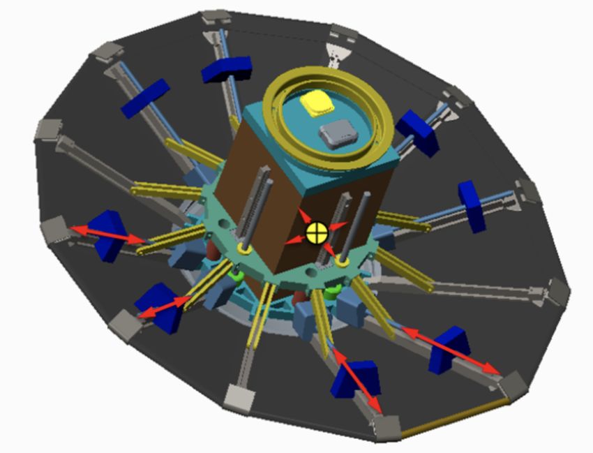
capability of the vehicles’s thermal protective system, and g-loads below 15 g?s are considered based on
   anticipated payload sensitivity to deceleration loads. Additionally, a secondary payload envelope on the Aft
   Bulkhead Carrier (ABC) of a Centaur V is utilized as a constraint for mass and volume for G&C designs,
   resulting in an assumed volume of 0.5 m x 0.5 m x 0.6 m and mass of 77 kg for the baseline vehicle [1, 8].
       The Pterodactyl Baseline Vehicle (PBV), the DEV used to demonstrate the integrated G&C solutions, is
   based on the Lifting Nano-ADEPT (LNA) [9], an asymmetric variant of the ADEPT (Adaptable, Deployable,
   Entry Placement Technology) vehicle [10]. The PBV has a flexible thermal protection system (TPS) that
   can be stowed during launch and deployed prior to or during entry [11]. This vehicle, depicted in Fig.
   1, has a nominal 1-meter diameter with two longer ribs on the trailing edge side of the vehicle to create
   an asymmetric surface and generate lift. In the lift-up configuration, these longer trailing edge ribs point
   downward; thus to increase lift, the vehicle pitches down and increases angle of attack in the negative
   direction. The reverse is the case - to decrease lift, the vehicle pitches up and increases angle of attack in the
   positive direction. To control the vehicle, we investigate three control architectures - Flap Control System
   (FCS), Reaction Control System (RCS), and Mass Movement Control System (MMCS). These architectures
   are independently integrated with the vehicle as depicted in Fig. 2 and brief overviews of the three control
   systems are given in Sections A through C. For additional details on the PBV and the control system
   hardware integration, Ref. [12] should be consulted.

Pterodactyl:Leading
              Precision
                    Edge
                         Targeting
                          Leading Edge of Deployable Entry
                                       Dr. Sarah D’Souza, Principal Investigator, sarah.n.dsouza@nasa.gov

   Imagine delivering
  payloads to planetary
bodies with the ease you
                                                                                                                        NEED:
send packages using UPS                                                                                                    to ena
  and at a reduced cost                                                                                                 autonom
                                                                V                                                        landing
 because you can deliver
  direct to your precise                                                                                                       pa
                                                                                           Trailing Edge
       destination!
                           Trailing Edge

                                                                SOLUTIONS
                                       Figure 1. Pterodactyl Baseline Vehicle

                 RCS                        Mass Movement                                   Flaps                       DEV wit

      Using an integratedFigure     SW2. &Control
                                               HW Hardware
                                                      designArchitectures
                                                               approach, Pterodactyl has
      developed multiple innovative guidance & control systems for
   A. precision
        Flap Controltargeting
                      System (FCS)   of deployable entry vehicles (DEVs) that
      increase
   Eight          maneuverability
         aerodynamic control surfaces, sizedand   maximize
                                             to provide       useable
                                                        maximum           payload
                                                                control authority whilevolume.
                                                                                        meeting packaging
   and stowing constraints [1], were affixed to eight of the ribs as depicted in Fig. 3. These flaps were
                                      The Team                                                         Hybrid Project M
   designed to provide the capability to follow (i) decoupled angle of attack and sideslip guidance commands
   and (ii) bank angle guidance commands if necessary. The longitudinal flaps (1, 2, 7, and 8) are designed to
   provide primarily pitch control by changing the vehicle’s angle of attack while the lateral tabs (3 - 6) are
             • ARC, Lead Center: Project Management, Mission Design, Control                          Leveraged agile and traditio
               Systems Design, Aero/Aeroheating, Mechanical Design and Structures,                       parallel development of
               Heatshield Design                     3 of 14                                            integrated hardware prot
             • JSC: Guidance & American
                                 Trajectory Designof Aeronautics and Astronautics
                                          Institute                                                       feasible, innovative flap
             • JHU Applied Physics Laboratory: Flight Operations, Systems Engineering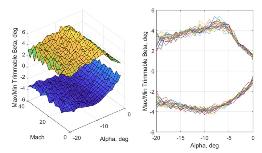
7

                       Leading Edge

                              Trailing
                               Edge

                       Figure 3. Fore and aft views of the PBV with control surfaces

designed primarily for yaw control through sideslip modulation. Deflecting longitudinal tabs 1 and 2 into
the flow generates a negative/downwards pitch moment while doing the same for tabs 7 and 8 generates a
positive/upwards pitch moment. When deflected into the flow, tabs 3 and 4 yaw the vehicle right while tabs
5 and 6 create a left yaw orientation. All tabs have a maximum of 20◦ deflection into the flow (+20◦ ) and
45◦ retraction (-45◦ ) out of the flow due to in-flight aerothermal limits and mechanical design integration
constraints, respectively [12, 13].

B.   Reaction Control System (RCS)
As shown in Fig. 4, four thrusters are mounted on the lateral ribs - the ribs on which the control surfaces 3-6
are affixed in the previous design . These thrusters fire in pairs and can independently generate 1N thrust
magnitudes. They are designed to provide roll control to change the vehicle’s orientation and track bank
angle guidance commands. Firing a pair of thrusters located on one side of the x-z plane will roll the vehicle
in one direction and change the bank angle while firing the opposite thruster pair rolls the vehicle in the
other direction and generates a bank reversal [12].

                              Figure 4. PBV depicting four reaction thrusters

C.   Mass Movement Control System (MMCS)
Similar to the flap design, eight 2 kg movable masses are integrated on eight ribs with maximum weights
chosen to meet packaging requirements [12]. These masses, depicted on the LNA in Fig. 5 are designed

                                                      4 of 14

                                American Institute of Aeronautics and Astronautics
to provide control of either angle of attack and sideslip or the bank angle, depending on the guidance
requirements. Unlike the flaps which generate aerodynamic moments when deflected into and out of the
flow, or the RCS that directly generates torques from thrusters, the moving mass system changes the vehicle
CG and inertia matrix by redistributing weight primarily in the y-z plane of the vehicle. This implies that
the CG shift realizable with this architecture is in the y and z directions primarily. As a result, this control
architecture will be investigated for angle of attack and sideslip control primarily.

                               Figure 5. PBV depicting eight movable masses

                                  III.    Simulation Development
    In this section, we give an overview of the Python-based simulation environment developed to simulate
the vehicle and evaluate the control design. First we briefly describe the aerodynamic model of the PBV
and how it is represented and utilized in simulation, after which we present the equations of motion for the
different control architectures. For extensive details on developing the integrated simulation framework, the
previous publications of the authors [14, 15] should be consulted.

A.   Aerodynamic Model
The aerodynamic forces and moments, F , and M respectively, can be represented as:

                                                 F = qSA CF
                                                                                                            (1)
                                                 M = qSA c CM

respectively, where SA is the reference surface area, c is a reference length, and q is the dynamic pressure.
Furthermore, CF and CM are the dimensionless aerodynamic force and moment coefficients respectively, and
can be represented as:
                              CF = CF,P BV (α, β, M ) + ∆CF,ACS (δ1 , . . . , δ8 )
                                                                                                          (2)
                              CM = CM,P BV (α, β, M ) + ∆CM,ACS (δ1 , . . . , δ8 )
where CF,P BV and CM,P BV are the aerodynamic force and moment coefficients respectively on the base
vehicle, due to its orientation (i.e. angle of attack and sideslip) and operating environment (i.e. Mach num-
ber). ∆CF,ACS and ∆CM,ACS are the incremental aerodynamic force and moment coefficients on the vehicle
induced only by the aerodynamic control surfaces (ACS). This implies that, for the two configurations with
no aerodynamic surfaces - reaction control system and moving mass system - the ∆CF,ACS and ∆CM,ACS
terms are automatically zero in the aerodynamic model.
    The aerodynamic force and moment coefficients were generated using Cart3D for a matrix of flight con-
ditions from the expected flight envelope [13] . Table 1 shows the flight conditions used to develop the
database. To utilize the data in analysis and simulation, multivariate B-splines [16, 17] were constructed to
smoothly interpolate the aerodynamic database at any Mach, angle of attack, sideslip, and control surface

                                                      5 of 14

                                American Institute of Aeronautics and Astronautics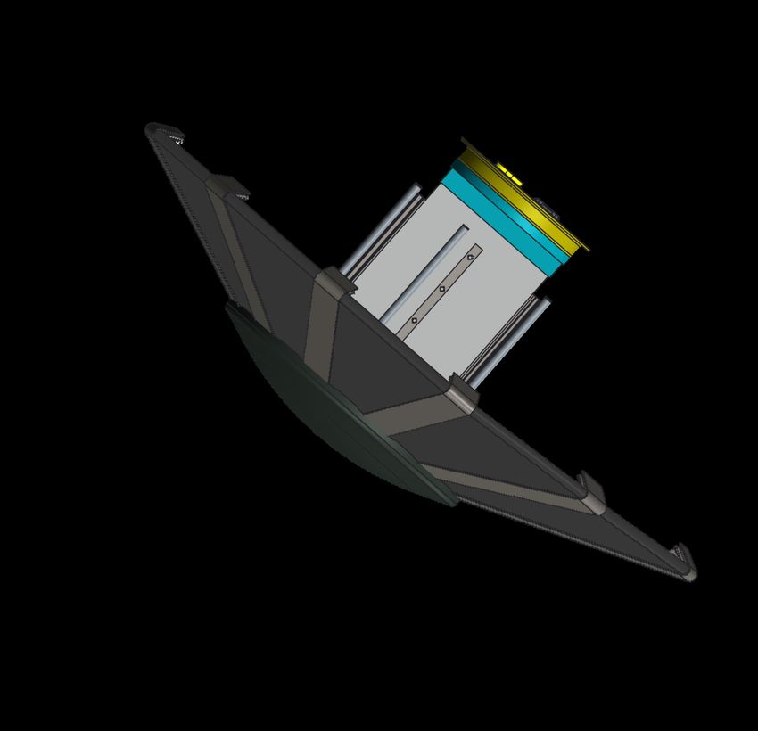
deflections. The interpolating spline curves were also differentiated to obtain dimensionless stability deriva-
tives such as the dihedral effect, pitch, stiffness, and yaw stiffness, to understand the stability characteristics
and limitations of the vehicle. Additional details are given in Ref. [14, 15].
Table 1. Flight Conditions for Aerodynamic Database Generation
Independent variable Values
Mach number M {40, 31, 20, 15, 10, 5, 2}
Angle-of-attack α, deg {0, ±5, ±10, ±15, ±20}
Sideslip angle β, deg {0, ±5, ±10, ±20}
Control surface deflection δi , deg {-45, -20, 0, 10, 20, 30}
B. Equations of Motion
For this study, we utilize previously developed equations of motion of a hypersonic re-entry vehicle as
described by Vinh [18]. We present the final forms of the linear and angular dynamics and kinematics
equations for the PBV independently integrated with the FCS, RCS, and MMCS control architectures.
The linear dynamics are given by
g (z) 1
V̇ = − sin (γ) − D
m m
g (z) V
γ̇ = − + cos (γ)
mV z
(3)
1
+ (L cos (σ) − S sin (σ))
mV
1
ξ˙ = (L sin (σ) + S cos (σ))
m V cos (γ)
where V is the velocity of the vehicle, γ is the vehicle flight-path angle, ξ is the vehicle heading angle defined
from due North, L, D, and S are the aerodynamic lift, drag, and side forces, respectively, g (z) is the force
due to gravity, dependent on the radial distance from the planet center z, σ is the bank angle, and m is the
mass of the vehicle.
The angular kinematics are defined by
σ̇ = p cos (α) sec (β) + r sin (α) sec (β)
α̇ = −p cos (α) tan (β) + q − r sin (α) tan (β) (4)
β̇ = p sin (α) − r cos (α)
where p, q, and r are the angular velocities about the body-fixed x, y, and z axes respectively, α is the angle
of attack and β is the sideslip angle.
The linear kinematics are given by
ż = V sin (γ)
V
Φ̇ = cos (γ) cos (ξ) (5)
z
V
λ̇ = cos (γ) sin (ξ)
z cos (Φ)
where Φ and λ are the latitude and longitude of the vehicle, respectively.
For the vehicle integrated with aerodynamic control surfaces, the angular dynamics are given by
ṗ −1 L p p
B/Bcm B/Bcm
q̇ = Ib M − q × Ib q (6)
ṙ N r r
6 of 14
American Institute of Aeronautics and Astronautics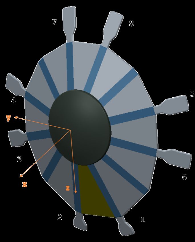
B/B
where Ib cm is the inertia tensor of the vehicle about its center of mass (COM) expressed in the body
coordinates and L, M, and N are the aerodynamic roll, pitch, and yaw moments, respectively.
For the vehicle integrated with reaction control systems, the angular dynamics are given by
ṗ −1 L LRCS p p
B/Bcm B/Bcm
q̇ = Ib M + MRCS − q × Ib q (7)
ṙ N NRCS r r
where LRCS , MRCS , and NRCS are the roll, pitch, and yaw torques, respectively, generated by the reaction
control thrusters.
For the moving mass system, the angular dynamics are derived from the angular momentum equation:
L I
d I S/S ∗
M = H (8)
dt
N
∗
where I H S/S is the angular momentum of the total vehicle system (including all movable masses), S, in
the inertial reference frame, I, about the total vehicle center of mass S ∗ . This can be expressed in terms of
the movable mass positions and inertial velocities,
I ∗ ∗ X 1 X ∗ X
H S/S = I B/B I ω B + δi × mi I v δi − mi δi × mB I v B + mi I v δi (9)
mS
where mi is the ith movable mass, mB is the mass of the PBV without movable masses, mS is the mass of
∗
the PBV with all movable masses, I B/B is the inertia dyad of the PBV body, B, without movable masses,
about the center of mass of B, denoted B ∗ . δi is the position of the ith movable mass from B ∗ in the B
fixed coordinate system, with δ̇i and δ̈i used to indicate the first and second time-derivatives in the B-fixed
∗
coordinate system. I v B is the velocity of point B ∗ in the inertial frame and Aω B is the angular velocity of
the B reference frame with respect to the inertial frame.
The derivative of the angular momentum on the right hand side of Eq. 8 produces the desired angular
accelerations ṗ, q̇, and ṙ. This equality can then be solved for the desired derivatives, resulting in the angular
dynamics equations for the vehicle with the moving mass system:
ṗ −1 L
B/B ∗
X 1 X X X
q̇ = I − (m δ × (δ × + m δ × m δ × M − mi δ̇i × I v δi
i i i i i i i
mS
ṙ N
" !#
B
X d I B∗ ¨ I B
− mi δi × v + δi + ω × δ̇i
dt
1 X ∗ X
+ mi δ̇i × mB I v B + mi I v δ i (10)
mS
!!
B B
1 X d I B∗ X d I B∗
+ mi δi × mB v + mi v + δ̈i + I ω B × δ̇i
mS dt dt
∗
− I ω B × I H S/S
IV. Control Design
In this section, the controller designed for each vehicle control architecture using the simulation framework
described in Section III is described. For each control hardware architecture, we design a linear multi-
input multi-output (MIMO) optimal state feedback integral controller using Linear Quadratic Regulator
techniques. The MIMO feedback controller is chosen because there are multiple guidance output commands
for the controller to achieve using multiple control effector inputs and these input-output interactions must
7 of 14
American Institute of Aeronautics and Astronautics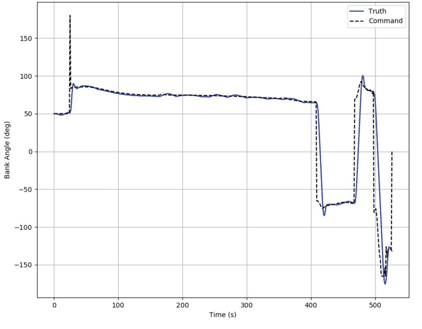
be handled in a structured, optimal manner. All controllers are designed to be capable of tracking feasible
guidance commands of angle of attack, sideslip angle, and bank angle (multi-output) using the different multi-
inputs (eight flap deflection values for the FCS, four reaction thruster commands, on or off, for the RCS, and
eight movable mass locations for the MMCS). The LQR approach also handles the control allocation effort
and enables the direct mapping to control input for the different configurations, making this control design
an attractive solution for the FCS, RCS, and MMCS configurations. For brevity, the MIMO LQR design
approach using the FCS is describedd and relevant changes to the control design for the RCS & MMCS are
noted.
    For the flap control system, to provide the ability for the controller to track bank angle, angle of attack,
or sideslip commands, the vehicle state is modeled as
                                                                            T
                                         x = [p q r σ α β eσ eα eβ ]

These states include the angular velocity components and vehicle orientation parameters, defined in Section
B and three additional augmented integral error state variables eσ , eα , and eβ . This augmentation is done
to reduce steady-state errors between the actual and commanded bank angle, angle of attack, and sideslip.
The derivatives for the integral error state variables are given by

                                                   ėσ = σ − σc
                                                   ėα = α − αc
                                                   ėβ = β − βc

where αc , βc , and σc are the guidance commands. The system control inputs
                                                                      T
                                              u = [δ1 δ2 · · · δ8 ]

are the hinge deflection angles of the eight aerodynamic control surfaces into or out of the flow. For the
states defined above, we linearize the equations of motion, at a nominal point in the flight envelope to obtain
state-space linear equations of the form

                                              ∆ẋ = A ∆x + B ∆u

where ∆x and ∆u are deviations from the linearization point x∗ , u∗ . The matrices A and B defined by
                                            ∂f                      ∂f
                                       A=                      B=
                                            ∂x   x∗ ,u∗             ∂u    x∗ ,u∗

are the state and input matrices respectively. Here, f (x, u) is the vector-valued function of the derivatives
for each state variable concatenated together.
    The control law is given as
                                               u = u∗ − K ∆x
where K is the feedback gain matrix, u∗ is a nominal control surface configuration, and ∆x is the state
deviation from the nominal trim configuration. The gain K is computed to minimize the quadratic cost
function                       Z ∞
                             J=        ∆xT (τ ) Q ∆x (τ ) + ∆uT (τ ) R ∆u (τ ) dτ
                                   0
where Q and R are tunable weighting matrices for the states and control surfaces respectively. Using the Q
matrix, we can tune the peformance and responses of the state variables and by tuning the R matrix, we
can define which and how much of a control variable to use.
   For the RCS configuration, the state variables are identical to the FCS configuration but the system
control inputs are reaction torques about the three body axes
                                                                            T
                                          u = [LRCS MRCS NRCS ]

These reaction torque inputs are obtained using the LQR control design and are then mapped to the jet
thrusters using a jet selection logic developed by Johnson et al [4]. The generalized jet selection algorithm
takes inputs along with the LQR required torques to output ON/OFF commands. Before flight simulation,
the jet selection tool is run to derive all torque combinations and pre-load into tables.

                                                          8 of 14

                                American Institute of Aeronautics and Astronautics
For the moving mass control configuration, since the velocities and accelerations of the movable masses
enter the equations of motion as seen in Eq. 10, we model the vehicle state to include these velocities and
accelerations as              h                                                     iT
                          x = p q r σ α β eσ eα eβ δ1 δ2 · · · δ8 δ̇1 δ̇2 · · · δ̇8

with the control input defined as the accelerations of the movable masses:
                                                   h                  iT
                                                u = δ̈1 δ̈2 · · · δ̈8

                             V.     Stability & Trimmability Analysis
    In this section, we present an overview of the stability of the PBV and evaluate the trimmable ranges
using the FCS configuration. In-depth stability analyses of the PBV can be found in prior publications of
the authors [14,15]. Thus, for brevity, the relevant static stability derivatives are summarized in Table 2 at a
maximum dynamic pressure flight condition obtained from an initial nominal guidance trajectory developed
in Ref. [1]. This flight condition corresponds to a Mach number of 32, dynamic pressure of 2492 Pa, angle of
attack of -15 degrees, and zero sideslip. Although, the dihedral effect, CLβ , the pitch stiffness, CMα , and the
yaw stiffness, CNβ are all stable as seen in Table 2, the non-zero dihedral effect CLβ implies that a non-zero
sideslip angle will induce a roll moment on the vehicle. Thus, any control architecture that commands a non-
zero sideslip angle as required by guidance, must also be capable of generating a roll moment to counteract
and trim out the associated induced roll due to sideslip. This implies that the alpha-beta (α-β) guidance
approach, which generates angle of attack and sideslip commands, will require control effectors capable of
generating pitch moments for α, yaw moments for β, and roll moments to trim the induced roll.

                                       Table 2. Static stability derivatives

                                  Stability derivative         Value        Stability
                                                                       −5
                                         CLβ               -8.6 × 10         stable
                                         CMα               -4.4 × 10⁻³       stable
                                         CNβ                4 × 10⁻³         stable

    The design of the FCS is to generate primarily pitch and yaw moments for α-β guidance. Also, the
PBV ribs, which are the attachment points of the control surfaces, are not aligned with the body y-z axes.
Thus, deflecting a control surface primarily for pitch will also generate a small yaw moment and vice versa.
As a result of the roll-yaw coupling and control surfaces generating pitch and yaw simultaneously, the
controllable angle of attack and sideslip ranges for the PBV using the FCS are significantly limited [14, 15].
In Fig. 6, the sideslip trimmability at different angles of attack and Mach numbers are depicted. These
ranges were acquired using a Newton-Raphson solver at different angle of attack and sideslip combinations,
using thousands of randomly seeded starting tab configurations. As a caveat, these trim conditions are not
necessarily unique and solutions depend on the initial conditions of the control surface deflections.
    These results extend to the MMCS configuration as well, which has an even smaller range of pitch and yaw
moment generation. The MMCS configuration generates smaller pitch and yaw moments due to the weight
limitations and available travel distance along the ribs for the masses [12]. This restricts the α-β guidance
bounds to ranges that reduce the precision targeting capability. The FCS and MMCS configurations of the
PBV have limited ability to trim out roll induced by holding a sideslip, thus a guidance approach, such as
bank angle guidance, which doesn’t require holding a non-zero sideslip, must be considered. A bank angle
command can be generated by yawing the vehicle and taking advantage of the induced roll generated by
the yaw. The reason that bank-to-turn works and skid-to-turn doesn’t is that a bank command needs to
generate rolling torque only when the roll is changing (i.e. when the vehicle reaches the desired steady-state
roll, no more rolling torque is required), whereas a sideslip command requires a constant reaction rolling
torque from the FCS and MMCS. Thus, the approach for these two architectures in the rest of the paper,
is to utilize the inherent coupling to track bank angle commands by instantaneously commanding, but not
holding, a sideslip angle. The RCS continues to be used directly as designed for bank angle guidance tracking
through the reaction thrusters.

                                                         9 of 14

                                  American Institute of Aeronautics and Astronautics
Figure 6. Trimmable Regions (a) Surface View (b) Trimmability Curves for Different Machs

                          VI.     Yaw-to-Bank Design and Evaluation
    For the FCS and MMCS, the core controls group developed a novel yaw-to-bank control architecture to
leverage the roll-yaw coupling and achieve high performance bank control. In this approach, the control
design is decomposed into an inner and outer loop. The outer control loop tracks bank angle commands
by commanding the appropriate sideslip which induces a roll moment through the dihedral effect. The
inner control loop tracks (i) angle of attack commands from guidance including regulation about a constant
angle of attack and (ii) sideslip commands generated by the outer control loop. A block diagram of this
architecture is shown Figure 7.

                                     αc
                                          /     / Kαβ            / ẋ = f (x, u)         /
                                                   O

                     σc
                          / Kσ       βc
                                          /                                  p,q,r,α,β

                             O

                                                                              p,q,r,σ

                                 Figure 7. Yaw to bank control block diagram

   To make a quick assessment of the bank angle tracking capability across the FCS, RCS, and MMCS
architectures, we select the maximum bank acceleration attainable by the control system, as an indicator
of maneuverability and a metric for control system performance. The dihedral derivative, CLβ , quantifies
the amount of roll moment, L, that is induced by a sideslip angle, β. This roll moment in turn affects
the angular acceleration about the body x axis, ṗ, as seen in the angular dynamics equations in Section
B. Taking the derivative of the bank angle rate, Eq. 4, introduces the body roll acceleration, ṗ, into the
bank angle acceleration, σ̈, as seen in Eq. 11. Although both the bank rate and acceleration, in Eqs. 4 and
11 respectively, also dependent on the yaw rate, ṙ, rigid flight vehicle dynamics, demonstrate that bank is
more related to roll than yaw as a roll is a rotation about the vehicle’s body x axis while bank is a similar
rotation about the velocity vector. Thus, for small angles of attack, the ṗ term dominates and is the primary
determinant of the bank acceleration.

                                                      10 of 14

                                 American Institute of Aeronautics and Astronautics
σ̈ = ṗ cos (α) sec (β) − p sin (α) α̇ sec (β) + p cos (α) sec (β) tan (β) β̇
(11)
+ ṙ sin (α) sec (β) + r cos (α) α̇ sec (β) + r sin (α) sec (β) tan (β) β̇
These dependencies demonstrate that the maximum sideslip angle that can be reached by the FCS or MMCS
is an indicator of (i) roll control authority through the dihedral effect, (ii) bank acceleration, and thus (iii)
bank maneuverability of the two architectures. Therefore, an estimate for the maximum bank acceleration
of these two control systems, is the largest sideslip magnitude that can be achieved by the control system.
This maximum sideslip can be obtained by solving for the sideslip at the maximum yaw configuration for
the vehicle. For the FCS, the flaps on one side of the x − z plane are deflected out of the flow to the
maximum retraction limit and the others are deflected into the flow to the maximum. For the MMCS, the
masses are moved all the way out on side and moved all the way in on the other side of the x − z plane to
generate the maximum yaw. Since the trim angle of attack, sideslip, and induced roll moment depend on
the flight condition, this analysis was performed and the control capability metric evaluated at two different
points in the flight envelope: (i) guidance and control initiation point and (ii) maximum dynamic pressure
location. The roll moment and bank acceleration of the RCS is independent of flight condition and is simply
determined by the position, orientation, and impulse capability of the thruster jets. The results are shown
in Table 3.
Table 3. Control Capability Comparison Across Architectures
parameter FCS MMCS RCS
max q G&C act max q G&C act
M 32 39 32 39 –
q (Pa) 2896 284 3021 298 –
α (deg) -10.65 -10.41 -11.10 -10.96 -16.28
β (deg) -19.39 -19.38 -7.40 -7.32 –
σ̈ (deg/s2 ) 115 11.5 13.8 1.48 10.9
L (Nm) 12.9 1.20 1.46 1.36 × 10⁻¹ 0.84
M (Nm) 1.54 × 10⁻⁶ 1.7 × 10⁻⁷ 5.23 × 10⁻⁷ 4.46 × 10⁻⁸ −4.02 × 10⁻³
N (Nm) −2.04 × 10⁻⁶ −2.3 × 10⁻⁷ −1.88 × 10⁻⁶ −1.29 × 10⁻⁷ −8.51 × 10⁻⁶
Table 3 shows the Mach number, M , dynamic pressure, q, angle of attack, α, sideslip, β, and bank accel-
eration, σ̈, along with the pitch, roll, and yaw moments for the FCS, RCS, and MMCS vehicle architectures
when the vehicle is at the maximum yaw right orientation. For the FCS and MMCS, these parameters are
presented at maximum dynamic pressure and G&C activation while for the RCS, the maximum bank angle
acceleration remains constant throughout the trajectory. Table 3 demonstrates that the maximum sideslip
angle using the FCS is significantly larger than that obtained from the MMCS. This impacts the bank accel-
eration results for which the FCS is capable of generating bank accelerations almost ten times the capability
of the MMCS. For good bank angle guidance performance for the chosen reference design mission [1], a
control system should be capable of achieving at least 5 deg/s/s bank acceleration rates [5]. At G&C acti-
vation, the MMCS falls short of this constraint, implying that certain bank maneuvers to achieve precision
targeting may not be attainable using this control configuration. Both the FCS and RCS configurations are
capable of meeting the constraints with the FCS having over ten times the RCS bank acceleration capability
at maximum dynamic pressure.
To that effect, we simulate responses to two different bank angle guidance trajectories developed for the
baseline vehicle integrated with the two different control architectures - FCS and RCS. Figs. 8 and 9 show
the vehicle tracking response using the FCS and RCS respectively. In Fig. 8 the angle of attack, sideslip,
and bank angle commands and responses along with the control surface deflections required to track the
commands are plotted. The sideslip is observed to change to generate a roll moment in accordance with
the outer loop bank angle command as described in the ”yaw-to-bank” design framework. When no change
in the bank angle is required, the sideslip is maintained at zero degrees, a tractable orientation for the
control surfaces to achieve. Furthermore, the angle of attack is held at a fixed value as there is no angle-of-
attack modulation required to correct downrange as in the α − β guidance scheme. Furthermore, the control
11 of 14
American Institute of Aeronautics and Astronauticssurfaces stay well within their saturation limits with control surfaces 7 and 8 at their maximum retraction
angle of 45 degrees out of the flow. This indicates that for this vehicle, FCS configuration, and guidance
trajectory requirements, fewer than 8 flaps are sufficient for control. Towards the end of the trajectory, slight
oscillations in the sideslip angle are observed with reduced tracking performance in angle of attack. This
may be rectified with better tuning or gain scheduling of the control gains as the gains were obtained for the
PBV with FCS operating at an earlier point in the trajectory. Fig. 9 also shows good tracking of the bank
angle commands using the RCS architecture, which is expected given its bank acceleration capability. Both
designs are promising and provide the capability of tracking bank angle guidance commands for the vehicle
and ensuring precision targeting.
Figure 8. Bank angle tracking using FCS (i) angle of attack, sideslip, and bank angle (ii) control surface
deflections, 1 - 8
Figure 9. Bank angle tracking using RCS
12 of 14
American Institute of Aeronautics and AstronauticsVII. Conclusion & Future Work
In this paper, we investigated three different control architectures for a Deployable Entry Vehicle (DEV) -
aerodynamic control surfaces/flaps (FCS), reaction control systems (RCS), and moving mass control system
(MMCS). These designs were independently integrated on the vehicle to generate moments that will enable
tracking (i) heritage bank angle guidance commands for lift modulation & coupled downrange/crossrange
control and (ii) unconventional angle of attack, α, and sideslip, β, guidance commands for independent down-
range and crossrange control. The novel and unconventional FCS and MMCS architectures were designed
to track α − β guidance commands while the RCS was designed to track heritage bank angle commands. It
was discovered that the asymmetric DEV under investigation, had a non-zero induced roll due to sideslip
that the FCS and MMCS architectures had limited capability to handle for the chosen mission. These two
architectures were designed to provide independent angle of attack and sideslip commands with limited con-
sideration for roll moment generation to trim. As a result, for this vehicle configuration, the FCS and MMCS
configurations as designed, could not provide the control authority to track α − β guidance commands.
Similar to the RCS control objectives, the FCS and MMCS were then utilized to track bank angle guidance
commands by taking advantage of the roll induced by briefly commanding but not holding a sideslip. A
measure of bank angle tracking capability, the maximum bank acceleration, was developed and investigated
to evaluate and compare the three architectures. The results showed that the FCS had the largest bank
angle acceleration in comparison the other two - RCS and MMCS. It was also demonstrated that the FCS
and RCS had the control authority to generate bank accelerations that exceeded the minimum required for
good performance and trajectory tracking while the MMCS did not meet the requirement. For this vehicle,
sample mission, mechanical design limitations, and control configurations as designed, the FCS architecture
is the most promising in achieving good trajectory tracking results. Future work will involve a robustness
analysis of the control design, investigation of the FCS performance at the later points in the flight envelope,
and possible gain scheduling to improve performance and reduce dither. In addition, a different PBV will be
studied to develop the α − β guidance and control G&C scheme for a DEV with reduced roll-yaw coupling
and demonstrate the feasibility of the novel G&C architecture for a more conventional DEV configuration.
Acknowledgments
The authors acknowledge the support of the Pterodactyl aerodynamics group, Ben Nikaido and Zane
Hays, the mechanical design lead, Bryan Yount, and the guidance lead, Breanna Johnson, for their data,
insight, and contributions to the body of work presented in this paper. The authors would also like to
acknowledge the support of the NASA Space Technology Mission Directorate (STMD) Early Career Initia-
tive Program Manager, Ricky Howard, the NASA STMD Entry Descent & Landing Principal Technologist,
Michelle Munk, and all internal and external Pterodactyl mentors who have supported this effort and pro-
vided valuable feedback and recommendations.
References
1 D’Souza, S. N., Okolo, W. A., Nikaido, B. E., Yount, B. C., Tran, J., Margolis, B. W. L., Smith, B. P., Cassell, A. M.,
Johnson, B. J., Hibbard, K. E., Barton, J. D., and Hays, Z., “Developing an Entry Guidance and Control Design Capability
using Flaps for the Lifting Nano-ADEPT,” AIAA Aviation and Aeronautics Forum and Exposition, 2019.
2 D’Souza, S. N. and Sarigul-Klijn, N., “Survey of Planetary Entry Guidance Algorithms,” Journal of Progress in Aerospace
Sciences, Vol. 68.
3 Okolo, W., Dogan, A., and Blake, W., “Alternate trimming methods for trailing aircraft in formation flight,” Journal of
Guidance, Control, and Dynamics, Vol. 38, No. 10, 2015, pp. 2018–2025.
4 Johnson, B. J., Cerimele, C. J., Stachowiak, S., Sostaric, R. R., Matz, D. A., and Lu, P., “Mid-lift-to-drag ratio rigid ve-
hicle control system design and simulation for human Mars entry,” 2018 AIAA Guidance, Navigation, and Control Conference,
2018, p. 0615.
5 JJohnson, B. J., Rocca-Bejar, D., Lu, P., Nikaido, B. E., Yount, Bryan C., D. S. N., and Hays, Z. B., “Pterodactyl:
Development and Performance of Guidance Algorithms for a Mechanically Deployed Entry Vehicle,” AIAA SciTech 2020
Forum, AIAA, Orlando, FL, January 2020.
6 Widnall, W. S., “The minimum-time thrust-vector control law in the Apollo lunar-module autopilot,” IFAC Proceedings
Volumes, Vol. 3, No. 1, 1970, pp. 136–153.
7 Martin, F. H. and Battin, R. H., “Computer-controlled steering of the Apollo spacecraft.” Journal of Spacecraft and
Rockets, Vol. 5, No. 4, 1968, pp. 400–407.
8 Alunni, Antonella I., D. S. N. Y. B. C. O. W. A. M. B. W. N. B. E. J. B. J. B. J. D. L. G. W. L. and Hays, Z., “Pterodactyl:
13 of 14
American Institute of Aeronautics and AstronauticsTrade Study for an Integrated Control System Design of a Mechanically Deployable Entry Vehicle,” AIAA SciTech 2020 Forum,
AIAA, Orlando, FL, January 2020.
9 Directorate, N. S. T. M., “Center Innovation Fund 2016 Winners Nano-ADEPT Lifting: Design Development for a Lifting
Flight Test Demonstration,” 2016.
10 Directorate, N. S. T. M., “Adaptable, Deployable, Entry, and Placement Technology (ADEPTSR-1),” 2019.
11 Cassell, A., Smith, B., Wercinski, P., Ghassemieh, S., Hibbard, K., Nelessen, A., and Cutts, J., “ADEPT, A Mechanically
Deployable Re-Entry Vehicle System, Enabling Interplanetary CubeSat and Small Satellite Missions,” 32nd Annual AIAA/USU
Conference on Small Satellites, SSC18-XII-08, Utah, August 2018.
12 Yount, B. C., Cassell, A. M., and D?Souza, S. N., “Pterodactyl: Mechanical Designs for Integrated Control Design of a
Mechanically Deployed Entry Vehicle,” AIAA SciTech 2020 Forum, AIAA, Orlando, FL, January 2020.
13 Nikaido, B. E., D’Souza, S. N., Hays, Z. B., and Reddish, B. J., “Pterodactyl: Aerodynamic and Aeroheating Database
Development for Integrated Control Design of a Mechanically Deployed Entry Vehicle,” AIAA SciTech 2020 Forum, AIAA,
Orlando, FL, January 2020.
14 Margolis, B. W., Okolo, W. A., Nikaido, B. E., Barton, J. D., and D’Souza, S. N., “Control and Simulation of a Deployable
Entry Vehicle with Aerodynamic Control Surfaces,” Astrodynamics Specialist Conference, 2019.
15 Margolis, B. W., Okolo, W. A., and D’Souza, S. N., “Control Design & Sensitivity Analysis for a Deployable Entry
Vehicle with Aerodynamic Control Surfaces,” International Astronautical Congress, 2019.
16 de Boor, C., A Practical Guide to Splines, Springer, 1978.
17 W. L. Margolis, B. and Lyons, K., “ndsplines: A Python Library for Tensor-Product B-Splines of Arbitrary Dimension,”
Journal of Open Source Software, Vol. 4, No. 42, 10 2019, pp. 1745.
18 Vinh, N. X., Busemann, A., and Culp, R. D., Hypersonic and Planetary Entry Flight Mechanics, The University of
Michigan Press, Ann Harbor, 1980.
14 of 14
American Institute of Aeronautics and AstronauticsYou can also read