ADELFE Design, AMAS-ML in Action - A Case Study
←
→
Page content transcription
If your browser does not render page correctly, please read the page content below
ADELFE Design, AMAS-ML in Action
                                      A Case Study

Sylvain Rougemaille, Jean-Paul Arcangeli, Marie-Pierre Gleizes, and Frédéric Migeon

                                         IRIT - SMAC
                                    118, route de Narbonne
                                  F-31062 Toulouse Cedex 9
    {sylvain.rougemaille, jean-paul.arcangeli, marie-pierre.gleizes, frederic.migeon}@irit.fr

       Abstract. The complexity of engineers tasks leads us to provide means to bring
       the Adaptive Multi-Agent Systems (AMAS) design to a higher stage of automa-
       tion and confidence thanks to Model Driven Development (MDD). This paper
       focuses on a practical example and illustrates the modifications that have been
       done to the ADELFE methodology. In the Design phase, we propose to use a Do-
       main Specific Modeling Language (DSML) for the specification of cooperative
       agents. We also, add a Model Diven Implementation phase using model trans-
       formation, DSMLs and code generation. These phases carry out a model centric
       process to produce and partially generate the system code. We present the use of
       our MD process applied to a simple, but very illustrative example: the foraging
       ants simulation.

1    Introduction

Our team works both on adaptation and Multi-Agent Systems, the result is that we
propose paradigms to manage adaptation at different conceptual levels. We propose an
approach which introduces the adaptation following three independent axes [1]. The
first one differentiates the system level adaptation, achieved according to AMAS prin-
ciples [2], from the agent adaptation, allowed by a flexible agent architecture [3]. The
second axis distinguishes functional adaptation (which concerns the system expected
functionality, i.e. the service performed) and operational adaptation (which concerns
execution mechanisms, i.e. means to perform services independently of the functional-
ity itself). At last, the third one concerns the adaptation time. The adaptation is qualified
as dynamic when it occurs at runtime and static when it occurs at design time.
     The combined capacities of these approaches, AMAS principles and flexible agent
architecture, enable to deal with systems which can be characterized as complex, due
to the complexity of the domain (coupling with the environment, numerous interacting
entities) or the one coming from the execution layer. Our proposal is to ease the design
of such systems by combining the different adaptation kinds (system/agent, function-
al/operational) within a tool that would assist the engineers all along the design. This
assistant would reduce domain complexity by automating the implementation of the
system, letting engineers focus on business concerns. Moreover, the complexity of the
execution support would be totally hidden thanks to generative tools.
This is the goal of our research, in which we try to combine several software tech-
nologies such as reflection, aspect orientation, components, software architectures for
implementation issues, as well as AMAS which ease to handle system complexity. In
order to make all these technologies cooperate, we use a model driven approach that al-
lows to integrate modelling and implementation tasks in a common environment, such
as Eclipse. All these ”good practices” and principles are specified and gathered in a
methodology called ADELFE, which is a development process based on the RUP (Ra-
tional Unified Process) and specialised for AMAS developing.
In this paper, we present a practical example of the join use of both AMAS and flex-
ible agent principles within the ADELFE Design and Implementation phases applied to
a simple, but very illustrative example: the foraging ants simulation. The following of
the paper is organised as follows. First is presented the context of this paper: section 2
for the ADELFE methodology and its adaptation to a MD approach and section 3 for
the case study. Thereafter, the paper focuses in section 4 on the several phases where
model transformations and code generations are used. In section 5, we analyse the work
presented according to engineers points of view. Finally, we discuss some related works
and lastely we conclude.
2 ADELFE 2.0
Fig. 1: The ADELFE 2.0 phases.
ADELFE1 is an agent-oriented methodology for designing Adaptive Multi-Agent
System (AMAS) [2]. The MAS developed according to ADELFE provided an emergent
global function [4]. The global function is qualified as emergent because it is not coded
inside the agent. The agents are not aware of this global function. Let’s take the example
of the robot transportation application developed with ADELFE [5] where the agents
have to transport boxes from a room to another one by passing through narrow corridors
(agents cannot pass each other). The agents have to move in an environment containing
2 rooms, 2 corridors, boxes, walls, others robots. Each agent’s local behaviour consist
in avoiding collision and in trying to be cooperative. The global phenomena not coded
1
ADELFE is a French acronym for ”Atelier de Développement de Logiciels à Fonction-
nalité Emergente”. It was a French RNTL-funded project (2000-2003) which partners
were: ARTAL Technologies (http://www.artal.fr) and TNI-Valiosys (http://
www.tni-valiosys.com) from industry and IRIT (http://www.irit.fr/SMAC)
and L3I (http://www-l3i.univ-lr.fr) from academia. See http://www.irit.
fr/ADELFEinside the agent is that a traffic direction emerges. To obtain this emergent behaviour, the system follows the AMAS theory [6] in which the agents are endowed with the abil- ity to autonomously and locally modify their interactions in order to react to changes in their environment. These alterations transform their collective function i.e. the global function performed by the MAS they belong to. This system is self-organising and is able to adapt to its environment. According to the AMAS theory, interactions between agents depend on their local view and on their ability to ”cooperate” with each other. Every internal part of the system (agent) pursues an individual objective and interacts with agents it knows by respecting cooperative techniques which lead to avoid Non Cooperative Situations (NCS) like conflict, concurrence etc. Faced with a NCS, a co- operative agent acts to come back to a cooperative state and permanently adapts itself to unpredictable situations while learning on others. 2.1 Adelfe 1.0 The ADELFE agent-oriented methodology aims at guiding AMAS designers through a development process based on the RUP (Rational Unified Process) [7], a standard process of object-oriented methodology. ADELFE covers the phases of a usual soft- ware design from the requirements to the design; it uses UML notation and extension of UML already done in AUML in particular the AIP (Agent Interaction Protocols) notations [8]. Our aim is not to add one more methodology to existing ones but to work on some aspects not already taken into account such as complex environment, dynamics, and adaptation. As this methodology concerns only applications designed following the AMAS theory, some activities or steps had been added to the RUP in order to be specific to adaptive multi-agent systems. In the preliminary and final re- quirements, the environment modelling and the expression of the situations that can be “unexpected” or “harmful” for the system had been added. In the analysis phase, two activities are dedicated to the AMAS. ADELFE helps the designer to decide if the use of the AMAS theory is required to implement his application. ADELFE provides also guides to identify cooperative agents among all the entities defined during the final re- quirements. Concerning the design phase, three activities are added. The first concerns the relationships between agents. The second is about the agent design. In this activity, the cooperation failures are defined. Then, a fast prototyping activity helps to build and verify the agent behaviour. 2.2 Extending Adelfe 1.0 Rationale The design phase of ADELFE was previously carried out using UML1.4 profile, to take into account cooperative agents and their specificity. Moreover, the AUML AIP (Agent Interaction Protocols) [8] has been extended to integrate cooper- ation failure. However, since its last version, UML2.0 [9] has integrated many of the desired features of the FIPA for AUML, making a step further in the AIP direction (adding the concepts of Combined Fragments to the sequence diagram, for instance). As a consequence, the profiles based on the previous UML version was kind of “dep- recated notations”. In the purpose of updating the ADELFE methodology, we begun a metamodeling process to characterise as precisely as possible the concepts involved
in the AMAS theory and mandatory for ADELFE. With this metamodel, we made the
choice of developing our own DSML (Domain Specific Modeling Language) [10], con-
sidering that the AMAS approach constitutes a domain on its own. We called this lan-
guage AMAS-ML (AMAS-Modeling Language). All along the metamodeling process,
we had in focus that this specific language would be used in the ADELFE methodology
for the purpose of specific design. Besides this fact, the abstraction and the concepts
that it brought have been used to initiate a model driven implementation phase.
In the ADELFE V.2, the design phase has been improved and an implementation
one has been added.
Design AMAS-ML is used in several steps of the design phase, from the detailed agent
structure design to the definition of the agent cooperative behaviour. This is done thanks
to specialised diagrams:
– The agent diagram: it is used to model the cooperative agent structure, as well as
its relationship with environmental entities. It defines all the specific features of a
cooperative agents, its Representations, Characteristics, Skills and Aptitudes.
– The behavioural rules diagram: it allows the specification of rules involved in the
decision process of an agent. It is expressed with the cooperative agents features.
Based on their representations and perceptions, agents have to decide next actions
to lead. These actions may be done in the purpose of NCS recovering (Coopera-
tiveRule) or not (StandardBehaviorRule).
– The interaction diagram: for the moment it corresponds to the UML 2.0 sequence
diagram. We have defined a transformation which allows us to integrate the proto-
cols and messages defined in the UML model into our AMAS-ML model. However,
we are studying the interest of developing our own diagram editor.
The next implementation phase takes as input the result of the design, that is the AMAS-
ML model.
Implementation As we have presented it in [1], this phase is guided by one main idea:
the separation of concerns. More precisely, we want to separate all that constitutes the
“operating” concerns (basic mechanisms of the agent), from all specific behaviour con-
cerns (the way agents use their tools to achieve their goals). To do so, we based this
phase on a specific tool which we have developed: MAY (Make your Agents Yourself).
It allows the description of agent micro-architecture (operating mechanisms) thanks to
a DSML: µADL (micro-Architecture Description Language). The architectural style of
the micro-component assembly and the MAY generation process give a kind of “ab-
stract agent machine” (we could say a application-dedicated API) which can be used
by the developer as an abstract layer to implement the behaviour of agents. This phase
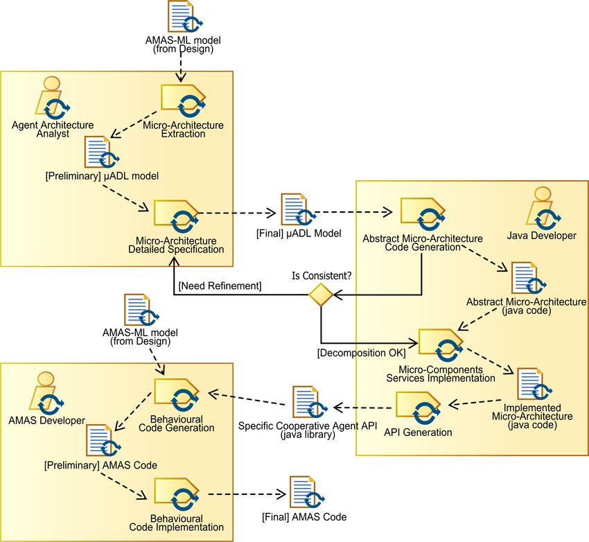
involves several generation or transformation steps which are illustrated in figure 2 with
SPEM 2.0 (Software and system Process Engineering Metamodel) [11]:
– Micro-Architecture Extraction : this is the first model to model transformation,
from AMAS-ML to µADL, which has been implemented with ATL [12]. It easesFig. 2: The ADELFE 2.0 Implementation phase in SPEM 2.0. the Agent Architecture Analyst tasks by creating a µADL model from the AMAS- ML model elements that we consider as “operating mechanisms” (see further sec- tion 4.3). – Abstract Micro-Architecture Code Generation : this first step of code generation gives code skeletons. Once the architecture is sufficiently refined and consistent, the Java Developer may implement micro-components services. – API generation : a this point, MAY generates the whole API, that is, tools to exe- cute, create and deploy the specific agent models. – Behavioural code generation : from the behavioural rules expressed in the design phase with AMAS-ML, we proposed to generate a code skeleton to ease the task of the AMAS Developer. The aim is to provide some hints to achieve the decision process of each agent in the system.
3     Case Study: the Foraging Ants

ADELFE has been used to develop a simulation of foraging ants, on one hand, for
providing a tool for ethologists and on the other hand, for testing that cooperative ants
following AMAS approach provide correct results. The application was chosen because
the behaviour of foraging ants is quite simple. The environment is composed of the nest,
some obstacles, pheromone, patches of food and ants. The pheromone self-evaporates
during time and can be accumulated when several ants drop pheromone at the same
place. The foraging ants have several characteristics. They have different degrees of
perception for obstacles, other ants, food, and pheromone. They always know where
their nest is located. They can carry a given quantity of food. They go out the nest for
a given duration and at the end of this duration, they go back to the nest and rest in the
nest. The foraging ant behaviour consists first in exploring the environment. When it
encounters an obstacle, it avoids it. When it encounters food, it can harvest it. When
it is loaded, it goes back to nest in dropping a given quantity of pheromone on the
ground. By consequence, tracks of pheromone appear in the environment. During its
exploration, an ant is attracted by pheromone and leads to follow pheromone track.
This behaviour implies a reinforcement of the existing tracks.

4     Applying Adelfe 2.0

This section depicts the way the application described above can be implemented thanks
to ADELFE and its model driven implementation phase. Thus, we focus mainly on the
last steps of the methodology, the first ones are summarised as they do not constitute a
new proposition.

4.1    Preliminary Steps: Requirements

These steps are devoted to the establishment of requirements and are usual in software
development methodology. They consist in a description of the problem domain as it is
demanded to be solved, as well as a specification of the final user needs. The first phase,
namely the Preliminary requirements phase, has already been completed. Although it
is not formalised, the brief description of the section 3 could be considered as its result.
It constitutes an overview of the requirements (user needs, key-words and limits).
Concerning the next phase, Final requirements, it is involved in the description of the
system environment and in the identification of the different elements which populate
it. From the requirements previously established we determine the following entities:

    – Passive Entities (resources for the system): the pheromone, obstacles, the food and
      the nest,
    – Active Entities (entities that could act autonomously): foraging ants.

Furthermore, from the requirements already presented we have characterised the envi-
ronment of the system as:

    – Accessible: its state is known by the system (simulation purpose);
– Non-deterministic: ants actions could have different results; – Discret: as a simulated environment it is defined as a grid; – Dynamic: ants actions modify continuously its state. From a more common point of view the Use cases identified for the system are all related to the management of a simulation tool: configuration of the ants parameters and observation of the results, and so on. Thus they are not extensively exposed in this paper. 4.2 Analysis After we have described the requirements, we proposed a first analysis which is in- tended to allow us to determine whether an AMAS approach is convenient or not. For- tunately it does! In fact, from global to local point of view and focusing on the ants activity observation, we can say that: – There is no obvious way to define the task of the colony; – The global task (food gathering) is performed by a great number of interacting entities; – These entities are conceptually distributed; – The environment is evolving during time; – Each ant possesses a limited perception of its environment, as well as a limited range of actions. Moreover they have to adapt themselves to an ever changing con- text. By analysing these few sentences, it seems that the AMAS approach is particularly well adapted to our problem. It also seems obvious that the agent in the previously identified entities could be none but the ant, in fact: – it is the only entity possessing an autonomous activity and trying to reach a personal goal (harvest food); – it has a partial vision of its environment, which moreover is evolving; – it has to deal with other entities and thus with potential cooperation failures. To sum-up the results obtained at this phase, we have determined that AMAS approach is appropriate to the problem we want to solve and thanks to the requirements too, we have identified the agent within the AMAS: the foraging ant. Since this point, and for the following steps we are focussing on the design and implementation of the cooperative agent. To do so, we have adopted a model driven approach rather than a code-centric one. 4.3 Model Driven Design and Implementation The beginning of the ADELFE methodology is based upon the RUP which is intrin- sically bound to the UML notation. Information contained by the model resulting of the preliminary steps of the method is necessary for the following phases. But, we also assume that UML models aren’t as specific as we want models to be for the design of
cooperative agents. To cope with this lack of specialisation, we have proposed our own
DSML (Domain Specific Modeling Language) based on an AMAS meta-model and
called AMAS-ML (AMAS-Modeling Language) [1]. However, this choice does not
prevent us for bridging UML preliminary models with AMAS-ML, in fact, we gather
their information to feed our AMAS specific model thanks to transformations. Further-
more, we use UML 2.0 sequence diagrams [9] to specify agent protocol [13] as well as
entities interaction, we extract from it the relevant information thanks to model transfor-
mations to. The next section presents the models which have been defined in the scope
of the foraging ants simulation tool design.

Agent Diagram For the precise design of the agents, we use the AMAS-ML agent
diagram (see figure 3 for details). According to the cooperative agent paradigm, an
agent is made up with several parts and modules. They represent its main abilities or
specificities such as : Representations, Characteristics, Skills and Aptitudes; they also
represent the way it interacts with its environment: action module, perception module,
action, perception and the means it involves actuators and sensors. In our example,
an ant does not use direct communication; it only deposes pheromone which could be
sensed by other ants (stigmergy), that is why no communication action could be noticed
in the figure 3. The perception consists in filling the different representations with fresh
values. For instance, the food array corresponds to the position where food has been
perceived. With these gathered positions and its skills (favour(), etc.), the ant agent
has to determine the better way to go. To do so, it fills the interpretedSurroundings
grid with integer values (the more appealing a position is, bigger is the integer value).
This decision process consists in the choice of the favourite positions. It is expressed
as rules and is described in the next section. As it has been presented in section 3, the
ants have to depose pheromone tracks in order to communicate the place where food
has been discovered. This task involved the use of a specific action dropPheromon()
which is fulfilled thanks to the ExocrynGland actuator. This information is useful for the
“extraction” of the agent architecture, it indicates which part of the agent is responsible
for the performing of an action (see section 4.3). The other specific features of the
ForagingAnt cooperative agent are shown in the figure 3 those features are used in the
next design step.

Behavioural rules diagram We distinguish two kinds of rules the Standard behaviour
which constitutes the local function or goal assigned to an agent; and the Cooperative
behaviour rules which are intended to manage Non Cooperative Situations. At this
step in the methodology, we are designing these rules as being triggered from an agent
state, which is itself characterized by a logical expression over the Representations,
Characteristics and Skills of the agent. A rule result in a set of actions, or skills that
have to be accomplished in order to reach a local goal or to recover a cooperative state.
The figure 4 shows an example of a graphical representation of those rules. The left
hand side presents states that triggered the actions at te right hand side. The rule binds
a state with actions and is labelled by a rectangle (in the middle of the figure) which
is also used to specify the kind of behaviour it is related to, cooperative or standard.
Actually, the figure 4 presents the avoidance of concurrence that could appear when
Fig. 3: AMAS-ML Agent Diagram: foraging ant cooperative agent detailed design.

ants are lusting for the same food patch and the standard ant behavior that consist in
going back to the nest while deposing a pheromone track when food has been collected.

µADL From the design phase and the AMAS-ML agent diagram, we propose to gen-
erate automatically an abstract agent architecture. This architecture is made up with
micro-components which specification could be edited and modified with the µADL
language. The result of this step is called the “Agent model”; it is used to generate a
specific API which is given to the developer in order to complete the following stages
of this phase. In the figure 5, the ant cooperative agent is shown as the result of a model
to model transformation from the AMAS-ML model of the figure 3. From this point,
an other model driven tool is used to proceed the last generation step, which is called
MAY (Make Your Agents Yourself), it is described in the next section.

MAY results MAY generates an dedicated API providing the agents modelled thanks
to µADL. In our case the agent model has been extracted from the results of the AMAS-
ML design (see 4.3). The abstract agent architecture has to be implemented, by reusing
micro-components or developing new ones. In our case, we choose to re-use micro-
components devoted to the interaction with a grid with a graphical representation which
was developed for a previous project. Once this task is completed, MAY can generate
the agent specific API that will be used for the development of the agent behaviour.
Fig. 4: AMAS-ML Behaviour Rules Diagram: concurrence avoidance cooperative rule
and returning.

4.4   Application code
At this stage, the work that still have to be done by the developer is the implementation
of the ant agent behaviour. We already possess some interesting information concern-
ing this behaviour which is contained by the AMAS-ML model (see section 4.3). There
is another code generation step which allows us to generate code skeletons and hints
for the implementation of the decision module. Concerning our example, the ant deci-
sion module consists in detecting patterns which modify the value of the interpretation
grid. This grid is given to the monteCarlo aptitude, which selects the next position to be,
thanks to a randomised algorithm. Thus the decision of the ant can be summarised as the
ponderation of this grid as well as the positioning of the headingToNestFull boolean,
thereafter the ant moves to the randomly determined position dropping pheromone if
necessary. We implemented the decide and the act methods wich are called by the Life-
Cycle micro-component.

5     Experiments Analysis
From the example presented here, and even if it does not constitute a “real world” or
industrial software development experiment, we can draw some conclusions at different
levels.

5.1   From the designer point of view
We have not presented here, for space saving convenience, the detailed design phase
as it has been done for the implementation phase. However, the use of the AMAS-ML
diagram has shown its interest in the cooperative agents design. Actually, the expres-
sion of behaviour as rules over the agent knowledge and characteristics has naturally
induced an incremental and iterative process in the precise design of agents features
Fig. 5: µADL diagram of the Ant cooperative Agent

and behaviour. Thus this two tasks benefit one from the other. For example, while ex-
pressing the cooperative behaviour of an agent a designer could need some new useful
skills. Conversly the adding of elements to the agent detailled design could bring some
situations that need to be handled by new behavioural rules.

5.2   From the developer point of view
The introduction of a model driven phase has brought a higher level of automation to
the AMAS development. Developers profit from model driven tools which help them
in the production of agent oriented software, domain they are probably not familiar
with. In fact, MAY offers to developers a way to produce their own agent oriented API
with a minimum of effort. In the mean time, this code generation process can still be
manually conducted by a MAS expert who would control every part of his/her code.
The implementation phase is a real model-driven process which keeps models and code
consistent.

5.3   From the method engineer point of view
We advocate that the implementation phase, thanks to its model driven approach, only
depends on the input “domain” model (AMAS-ML model in our case). Consequently,
it could be considered as a method fragment [14], parameterized by the domain model
and of course the associated transformation. One can object that this transformation
could be a problem, but we assume that MDD already offers means to assist its defini-
tion2 . Furthermore, the target model, namely µADL, offers a reduced set of concepts
that could be mapped easily. However, transformation generation still constitutes a chal-
lenging issue in the MD world.

6     MAS and MDE Related Works

Currently, some existing agent-based methodologies INGENIAS [15], PASSI [16], and
TROPOS [17] use model transformations in order to design MAS. These methods and
the associated tools coming from MDE are reviewed and briefly analysed in this section.
Few works on MAS engineering have involved the use of tools coming from MDE, and
the most advanced are: MetaDIMA [18], INGENIAS, TROPOS and SODA [19].
    MetaDIMA helps the designer to implement MAS on the DIMA platform using
MetaGen which is a MDE tool dedicated to the definition of metamodels and models.
DIMA is a development and implementation platform developed in Java where agents
are seen as a set of dedicated modules (perception, communication, etc.). MetaDIMA
provides a set of metamodels and a set of knowledge-based systems on top of DIMA to
ease the design of MAS by providing languages more specific than Java code.
    INGENIAS proposes to transform the MAS expressed in the INGENIAS meta-
model in code dedicated to a given platform using the modelling language of INGE-
NIAS and the implementation model of the platform. Its main originality consists in
providing evolutionary tools. Because tools used for transforming specification in code
are based on metamodels, if the metamodel specifications evolve, the tools can also
evolve. Moreover, these transformations are expressed as templates which also can be
tuned for specific purposes.
    In TROPOS, all the phases use different models which are described by metamod-
els; it also uses UML notation and automatic transformations. For example, it translates
plan decomposition into a UML 2.0 activity diagram by using a transformation lan-
guage based on the following three concepts: pattern definition, transformation rules
and tracking relationships.
    Molesini et al. [19] propose to fill the gap between methodologies and infrastruc-
tures by using metamodelling for mapping the abstractions at the AOSE methodology
level onto the abstractions at the infrastructure level. They provide guides for mapping
SODA concepts onto three different infrastructures: TuCSoN, CArtAgO and TOTA.
    Our work pursues the same objective as the works described previously although it
addresses the adaptation issue from both system and agent points of view. In fact, we
aim at taking it into account and providing design and generation tools to implement
such adaptive systems. For this purpose, we propose to generate an adapted execution
platform for AMAS, using MDE tools and principles as well as the flexibility provided
by MAY.

 2
     http://www.eclipse.org/gmt/amw/
7 Conclusion
In this paper, we have presented an example of the practical use of Domain Specific
Languages, model transformations, and code generation in the scope of a dedicated
methodology. That is to say, a whole Model Driven Engineering process devoted to the
implementation of an AMAS. The benefits of such an approach have been analysed
from several points of view, and even if some technical works still have to be done to
integrate this approach in a specific tool, we assume that the results are quite satisfying.
The implementation phase process still needs some adjustments, nevertheless the expe-
rience gained from its further practical application should bring us useful material to
do so. Moreover, the ADELFE v.2 methodology has been applied to other projects (for
example a Manufacturing Control Simulation) from which we already gather interest-
ing information about the implementation phase. Finally, our team is leading works on
the definition of specialised micro-architectures and micro-components that are going
to enrich the MAY library and thus favour reusability.
References
1. Rougemaille, S., Migeon, F., Maurel, C., Gleizes, M.P.: Model Driven Engineering for De-
signing Adaptive Multi-Agent Systems. In: The 8th annual International Workshop on Engi-
neering Societies in the Agents World: ESAW, http://www.springerlink.com, Springer (2007)
(on line)
2. Bernon, C., Camps, V., Gleizes, M.P., Picard, G.: Engineering Adaptive Multi-Agent Sys-
tems: The ADELFE Methodology . In Henderson-Sellers, B., Giorgini, P., eds.: Agent-
Oriented Methodologies. Volume ISBN1-59140-581-5. Idea Group Pub, NY, USA (2005)
172–202
3. Leriche, S., Arcangeli, J.P.: Adaptive Autonomous Agent Models for Open Distributed Sys-
tems. In: International Multi-Conference on Computing in the Global Information Technol-
ogy (ICCGI), Guadeloupe, 04/03/2007-09/03/2007, http://www.computer.org, IEEE Com-
puter Society (2007) 19–24
4. Georgé, J.P., Edmonds, B., Glize, P.: Making self-organising adaptive multiagent systems
work. In Bergenti, F., Gleizes, M.P., Zombonelli, F., eds.: Methodologies and Software En-
gineering for Agent Systems. Kluwer Academic Publishers (2004) 319–338
5. Picard, G., Gleizes, M.P.: Cooperative Self-Organization to Design Robust and Adap-
tive Collectives. In: International Conference on Informatics in Control, Automation and
Robotics (ICINCO), Barcelona, Spain, 14/09/2005-17/09/2005, http://www.insticc.net/, IN-
STICC Press (2005) 236–241
6. Capera, D., Georgé, J.P., Gleizes, M.P., Glize, P.: The AMAS Theory for Complex Problem
Solving Based on Self-organizing Cooperative Agents . In: TAPOCS 2003 at WETICE 2003,
Linz, Austria, 09/06/03-11/06/03, IEEE CS (2003)
7. Jacobson, I., Booch, G., Rumbaugh, J.: The Unified Software Development Process.
Addison-Wesley (1999)
8. Odell, J., Parunak, H., Bauer, B.: Representing Agent Interaction Protocols in UML.
Springer Verlag (2000)
9. Object Management Group, Inc.: Unified Modeling Language (UML) 2.0 Superstructure
Specification. (2003) Final Adopted Specification.
10. France, R.B., Rumpe, B.: Domain specific modeling. Software and System Modeling 4(1)
(2005) 1–311. Object Management Group, Inc.: Software & Systems Process Engineering Metamodel
Specification v2.0. Omg edn. (2007)
12. Jouault, F., Kurtev, I.: Transforming models with ATL. In: Proceedings of the Model Trans-
formations in Practice Workshop at MoDELS 2005, Montego Bay, Jamaica (2005)
13. Bauer, B., Odell, J.: UML 2.0 and agents: how to build agent-based systems with the new
UML standard. Engineering Applications of Artificial Intelligence 18(2) (2005) 141–157
14. Cossentino, M., Gaglio, S., Garro, A., Seidita, V.: Method fragments for agent design
methodologies: from standardisation to research. Int. J. of Agent-Oriented Software En-
gineering 1 (2007) 91–121
15. Gomez-Sanz, J., Pavon, J. In: Agent Oriented Software Engineering with INGENIAS. Vol-
ume Multi-Agent Systems and Applications III. Springer (2003)
16. Cossentino, M., Gaglio, S., Sabatucci, L., Seidita, V.: The PASSI and agile PASSI MAS
meta-models compared with a unifying proposal. In Pechoucek, M., Petta, P., Varga, L.Z.,
eds.: CEEMAS. Volume 3690 of LNCS., Springer (2005) 183–192
17. Bresciani, P., Perini, A., Giorgini, P., Giunchiglia, F., Mylopoulos, J.: Tropos: An agent-
oriented software development methodology. Autonomous Agents and Multi-Agent Systems
8(3) (2004) 203–236
18. Jarraya, T., Guessoum, Z.: Towards a model driven process for multi-agent system. In
Burkhard, H.D., Lindemann, G., Verbrugge, R., Varga, L.Z., eds.: CEEMAS. Volume 4696
of Lecture Notes in Computer Science., Springer (2007) 256–265
19. Molesini, A., Denti, E., Omicini, A.: From AOSE methodologies to MAS infrastructures:
The SODA case study. In: The 8th annual International Workshop on Engineering Societies
in the Agents World: ESAW, http://www.springerlink.com, Springer (2007) (on line)You can also read