Achievement of the $100/m2 Parabolic Trough - SkyFuel
←
→
Page content transcription
If your browser does not render page correctly, please read the page content below
Achievement of the $100/m2 Parabolic Trough

              Nathan Schuknecht1, a) Jennifer McDaniel2, b), and Harrison Filas 3, c)

1
    SkyFuel, Inc. Director of Research and Development. 200 Union Blvd, Suite 590. Lakewood, CO, USA 80228 Office: 303.749.5676.
    2
        SkyFuel, Inc. Senior Mechanical Design Engineer. 200 Union Blvd, Suite 590. Lakewood, CO, USA 80228 Office: 303.749.5670
         3
             SkyFuel, Inc. Mechanical Design Engineer. 200 Union Blvd, Suite 590. Lakewood, CO, USA 80228 Office: 303.749.5656

                                   a)
                                        Corresponding author: Nate.Schuknecht@SkyFuel.com
                                                 b)
                                                    Jenni.McDaniel@SkyFuel.com
                                                  c)
                                                     Harrison.Filas@SkyFuel.com

Abstract. It has long been a goal of the Concentrating Solar Power (CSP) industry to supply parabolic troughs for
electricity generation for less than $100/m2. This benchmark has now been achieved, with a product that is available for
commercial delivery in 2018. After years of continued development, research support from the US Department of Energy
(DOE), and a shift to a global supply chain, SkyFuel® has now achieved a Cost of Goods Sold (COGS) for the SkyTrough®
DSP parabolic trough collector of less than $100/m2 (2017 US Dollars).

This achievement required a holistic approach to parabolic trough analysis, with the development effort based on efficiency
analyses, material indices, labor rates, manufacturing and assembly methods, and worldwide supply chain logistics. The
following text describes in detail the base assumptions, optimization strategy, component design, manufacturing approach,
and supply chain logistics undertaken to achieve this goal.

As a result of the analyses, the primary material of construction changed from aluminum to steel. The aperture of the
trough increased from six to seven meters, and extended to a total collector length of 146 m. There are four receivers per
module, each 4.51 m long by 80 mm diameter, and eight modules in a Solar Collector Assembly (SCA). After analyzing
torque tubes, torque boxes, and monocoque structures as a comparison, a space frame design was selected as the primary
structural support; however, the frame has been reduced in relative size and has assumed a new geometry. The trough’s
reflective surface was also assessed against thick glass mirrors, thin glass mirrors, composite stacks, and thin-film polymer
reflectors. A thin-film polymer reflector was selected as the reflective surface, due to its low cost of materials and savings
from shipping and installation.

This collector is designed for use with a variety of working fluids including molten salt, with an outlet temperature of up
to 565°C. Use of molten salt as the collector working fluid reduces storage volume, improves plant efficiency, and allows
for operation in parallel with fossil-fueled boilers for hybridized utility-scale power applications. It has built-in electrical
isolation and salt-compatible flexible piping connections, a reduced-cost drive system, and a parabolic rib design that
contributes to its high efficiency and low cost. This publication documents the fundamental approach taken to achieve a
COGS of $100/m2, detailing the methods used in the analysis and the unique characteristics of the resulting product.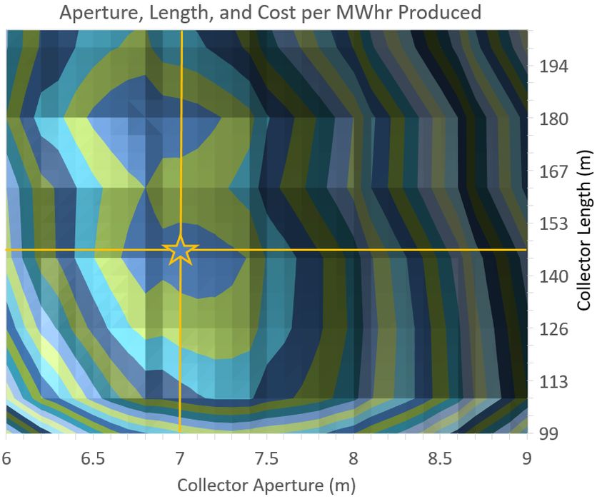
BACKGROUND AND ASSUMPTIONS

    SkyFuel is a company dedicated to the design and implementation of parabolic trough equipment for solar power
generation and process heat applications. In 2010, the National Renewable Energy Laboratory (NREL) tested the
SkyTrough parabolic trough collector, and found that it performs with an optical efficiency of 77.3% [1]. This
efficiency was achieved with a highly-reflective polymer film reflector and a collector that does not require manual
adjustments or assembly buildings. Now the design has been adapted to a larger-aperture, lower-cost parabolic trough
collector. SkyFuel began its SkyTrough DSP development under a DOE cooperative research agreement in 2010. In
2013, a report [2] was published at SolarPACES detailing the approach taken for the design of a trough that optimized
both performance and cost. The optimization method established by that report became the basis for the design of this
collector, and with the same focus on quality, reliability, and optical efficiency, the cost of this utility-scale parabolic
trough collector has been reduced to under $100/m2.
    The new design of the SkyTrough DSP increases the strength of the frame, mirrors, and structural members while
reducing component cost. Nearly all components were designed for a Chinese supply chain, and the hydraulic drive
system underwent a complete redesign to reduce weight while maintaining tracking accuracy and performance. Every
component in the SCA was optimized for the larger aperture and was fully analyzed for cost and performance.
    Unlike alternate low-cost troughs on the market, the SkyTrough DSP was developed specifically for highly-
efficient power generation on a utility scale. It is designed to operate with a bulk fluid temperature of up to 565°C.
This high temperature operation enables cost-effective thermal storage for power delivery in periods of low solar
irradiance and can increase thermal-to-electric conversion efficiency.
    Wind loads for the structural analysis were based on regions in northern and central China where CSP is expected
to be prevalent, and equate to a 3-second gust with a Mean Recurrence Interval (MRI) of 50 years or greater. While
the previous-generation collector was designed for gusts of up to 37.5 m/s (84 mph), the SkyTrough DSP will
withstand gusts of 40 m/s (90 mph) or greater without significant damage. So, while the SkyTrough DSP has been
reduced in cost, it is also more robust than previous platforms. All components in the SkyTrough DSP have been
designed with coatings that guarantee a minimum lifetime of 30 years in the field.

                                  EFFICIENCY AND SYSTEM DESIGN

    At the outset of the design effort, a decision was made to maintain the high efficiency of the previous product, and
a design goal of 76% was set for optical efficiency. Many low-cost parabolic troughs have been designed for process
heat applications and suffer reductions in efficiency that are not suitable for utility scale electricity generation. Figure
1 presents the relationship between efficiency and
solar field cost on a square-meter basis for
electricity generation, which yields an average
value of $3.76/m2 for each point of efficiency.
This data was derived from analyses performed
using the System Advisor Model (SAM)
published by NREL. In the study, the Levelized
Cost of Energy (LCOE) was maintained constant,
while optical efficiency and cost were iteratively
reduced and the system re-optimized. Each data
point presents the optimum solar field size and
storage volume for a given optical efficiency, with
only the solar field cost adjusted to maintain
LCOE. In the SkyTrough DSP design effort, a
reduction of $50/m2 was achieved for only a 1%
reduction in optical efficiency, an order of
magnitude greater than the baseline identified by
the efficiency study. Comparatively, a parabolic
trough with 72% optical efficiency would require
a COGS of $85/m2 to match the LCOE of this
design, and a trough with an optical efficiency of        FIGURE 1. Optical Efficiency Required to Maintain LCOE and
                                       2                                Financial Return on a 100MW Plant
68% would require a cost of $70/m . The design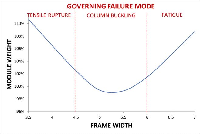
optimization for this product was performed with this cost/performance metric in mind, in such a way that cost
reduction did not adversely impact efficiency. While the design changes and sourcing decisions made to date have
each exceeded the cost/efficiency benchmark of $3.76/m2, the holistic approach taken in this effort has identified the
vast majority of cost reduction opportunities, and further gains from this point that achieve the same metric will be
challenging to realize.
    In the design optimization of 2013 [2],
assumptions led to a 90 mm x 4.72 m receiver
tube, an aperture of 7.6 m, and a collector length
of 150 m. Since that time, receiver prices have
dropped substantially, which has pushed
optimization toward a comparatively lower
aperture.     However, these same lower-cost
receivers have also yielded a reduction in thermal
efficiency, which tends to push designs toward a
higher concentration ratio to reduce heat loss.
This new receiver information was input to the
optimization model of 2013, and resulted in a new
optimum aperture of 7.0 m, with a receiver
diameter of 80 mm and a collector length of 146
m. The results of this study are presented in
Figure 2. Material cost and availability drove the
selection of the receiver length to 4.51 m, reduced
from 4.7 m in 2013. A 2014 paper [3] presented
the optical efficiency of the 7.6 m trough, which
exceeded expectations and allowed for a
reduction in receiver diameter from the originally-
designed 90 mm tube. This reduction has a small           FIGURE 2. Result of System Design Analysis, Yielding an
net benefit to capital cost, but greatly increases         Optimum Collector Size of 7m Aperture x 146m Length
plant performance due to the concentration ratio
increase and corresponding reduction in heat loss.

                    MANUFACTURING, SUPPLY CHAIN, AND LOGISTICS

    To take full advantage of China’s 10GW CSP initiative in their 13th Five-Year Plan [4], a strategic decision was
made to fully develop a supply chain in China to supply Chinese-based projects. This choice led to a reevaluation of
materials indices and fundamental assumptions inherent in parabolic trough design. Historically, SkyFuel has chosen
aluminum as its structural material, but has
based that decision on material properties and
the associated costs of a supply chain based in
the United States. Moving sourcing to China
provided a cost reduction across the board, but
the reduction is not consistent among materials.
The US Department of Commerce currently
issues dumping margins and subsidy rates on
aluminum [5] and steel [6] imports from China.
When compared to US-based pricing, these
duties indicate that cost reduction is up to 22%
greater for Chinese steel than it is for Chinese
aluminum. Figure 3 presents this difference
and the impact that it has on the material
decision for product design.
    With the selection of steel, components
utilize roll-form and progressive stamping          FIGURE 3. Cost Reduction Percentages for Steel and Aluminum
manufacturing methods to provide economic                            with a Chinese Supply Chain
advantages and mass-scale production. Worldwide, these methods are some of the most common and automated,
making them low cost and widely available. Using pre-coated steel coil and advanced coil line technologies,
components are manufactured more quickly, more accurately, and with reduced scrap rates. Labor and handling
expenses are significantly reduced, and parts have higher consistency. The change from American aluminum to
Chinese steel has resulted in a 70% cost reduction in select components.
The receiver tubes account for roughly 25% of the cost of a concentrated solar collector, and in the 2013 study,
molten salt receiver tubes were expected to cost $28/m2, with projected reductions of up to 25% by 2017. With receiver
tube manufacturing relocated to China, however, prices are now estimated at nearly 50% the price they were in 2017.
The expanding market for parabolic trough receivers has also provided more options in receiver length, allowing
improved collector optimization, reduced thermal losses, and ultimately, a lower cost per unit length.
While not directly related to the COGS, consideration was made to minimize shipping and field assembly costs.
By bolting together torque plate components, drive pylon sections, and rib halves in the field, even the largest
components achieve maximum packing density and minimized shipping costs. These sections bolt together without
the need for large assembly stations in the field. In 2015, NREL published a cost analysis [7] which independently
assessed the costs for both a SkyTrough SCA and a traditional glass facet SCA. For a commercial scale installation
of 100 MWe, a substantial assembly station was required for the glass facet SCA, amounting to an estimated $10/m2
in increased capital cost. The use of precision ribs with slide-in mirror panels and blind, quick-pull rivets does not
require an assembly station in the field. The SkyTrough DSP employs these assembly methods in a manner that
maintains the high-precision components and meets all optical accuracy and performance expectations.
COMPONENT OPTIMIZATION
Throughout the design of the SkyTrough DSP, each component was analyzed for both cost and performance, with
the goal of maintaining a $100/m2 COGS. The following sections describe the steps taken for each of the major
subassemblies of the parabolic trough, including the frame, reflectors, parabolic ribs, and drive system. Finally,
protective coatings are examined, as they are fundamental to each of the component designs. The result of this design-
to-cost exercise is a highly efficient and low cost solar collector suitable for the utility-scale power market.
Frame
The frame of the collector is the primary carrier of wind-induced torque, and structurally supports the optical
surface. As it typically accounts for about 25% of the cost of a parabolic trough, many approaches have been taken
to reduce the cost. In the evaluation of this collector, weight and stiffness were analyzed for various frame designs
including torque tubes, torque boxes, monocoques, and space frames. Across all designs, frame width and weight are
inversely proportional; as the frame width decreases, the weight of the frame increases to carry the required torque.
However, considering the extended length of space
frame members in a large-aperture trough, buckling and
fatigue become governing factors in the analysis.
Considering the frame styles presented above, the space
frame proved to be the most efficient design, however it
yielded an optimum frame width that was less than the
collector aperture. Equal length members were used to
improve field assembly time, reduce packaging
requirements, and optimize shipping. They also
provided tooling savings, and reduced part count. As a
result, a new, patent-pending space frame geometry with
exceptional torque-carrying capacity was implemented.
In the previous generation of this product’s design,
wind-induced fatigue governed the design of the 6 m
frame, and safety factors for other failure modes were
unnecessarily high. By reducing the length of the
members and switching to steel, fatigue is no longer the FIGURE 4. Frame Width vs Module Weight, Presenting
limiting failure mode. The module is designed more Governing Failure Mode
efficiently and with more traditional safety factors forother failure modes. As presented in Figure 4, the trough’s weight is reduced with a 5 m width frame, where column
buckling is the governing failure mode.
With the switch from aluminum to steel, the frame member connecting nodes are now made as die stamped parts,
as opposed to extruded aluminum. Thin sheets of steel can be accurately stamped into the required shapes, and nesting
of the pieces reduces scrap. Drawn edges add strength and stiffness to the parts without increasing material thickness,
and the final assemblies are riveted and welded together at the manufacturer to maintain the high accuracy required
for optical efficiency.
With about 25% of the collector cost coming directly from the frame, it was integral to the cost reduction process
to use a lightweight structure for the trough. The patent-pending geometry maintains the required torsional stiffness
while using fewer unique parts, and combined with lighter-weight structural members, effectively reduced the cost of
the frame by 47% on a m2 basis.
Reflectors
As with previous generations, the SkyTrough DSP maintains the use of ReflecTech mirror film as the reflector
surface for the trough. The film is laminated onto thin metal sheets to form the mirror panels, which have advantages
over glass mirrors as they are virtually indestructible, allow for rapid installation, and require fewer structural support
elements. In the initial product optimization phase of this design effort, ReflecTech mirror panels were analyzed
against glass facets to establish the most economic
choice. As described in NREL’s parabolic trough
cost analysis [7], the supporting structure for
traditional glass mirrors is 37% heavier than the
structure required to support ReflecTech mirror
panels.
Changing the reflector’s lamination substrate
from aluminum to steel provides additional
savings on top of the cost demonstrated by NREL.
The mirrors are designed to prevent plastic
buckling from occurring during high wind events;
for an aluminum panel, a thickness of 1.2 mm was
required to prevent buckling with a 6 m aperture.
For a 7 m aperture, a steel panel thickness of 1.2
mm proved to be more material than required. As
presented in Figure 5, reducing the steel panel
thickness to 1.0 mm provided improved buckling
resistance even with an increased aperture. This
reduction in thickness saves an estimated 1.6 kg
of steel per square meter of mirror surface. FIGURE 5. Buckling Resistance of Steel and Aluminum Reflector
As a result of the material change and supply Sheets as a Function of Aperture and Wind Speed
chain in China, the reflector panels have reduced
in cost by 32% on a m2 basis.
Parabolic Ribs
Parabolic ribs support the reflector panels, provide the backing for the precise parabolic optical surface, and
connect the reflector panels to the space frame. In competing glass-based collectors, the parabolic ribs are synonymous
to the cantilever arms that support the glass panels. Cantilever arms can account for as much as 1/3 the cost of a
parabolic trough [7], but due to the extended width of the SkyTrough’s space frame, the parabolic ribs account for less
than 10% the cost of the collector. When modified from a full-width frame to one with partially-cantilever rib
supports, the rib became more structurally significant than in prior designs. The rib now carries a significant moment
at the outermost frame connection, and must support the reflector as a cantilever load near the rim of the collector.Optimization of the rib was dependent on both minimizing weight and developing the design for manufacturing.
To determine the minimum required strength of the rib, wind loads were calculated from NREL’s Wind Tunnel Tests
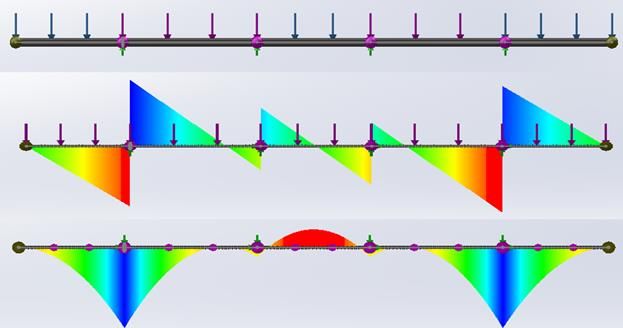
of Parabolic Trough Collectors [8]. As presented in Figure 6, applying the worst-case loading configurations to the
rib in the form of a pin-supported indeterminate
beam, shear forces and moments are carried
through the structure. The maximums and
minimums from all combined data sets defined
the parameters for the design of the rib
components. Based on the American Institute of
Steel Construction code [9], the necessary rib
web width and thickness was calculated to
prevent flexural yielding, lateral-torsional
buckling, and flange/stem buckling of the
member from the applied wind loads.
With the minimum structural requirements
determined, the web components were nested
based on coil fabricator recommendations for
FIGURE 6. Parabolic Rib Loading Condition and Resulting Shear
low-cost and common width. Because little to no
and Moment Diagrams
savings is realized from scrap material, the
resulting gaps between ribs were included
within the rib web for additional stiffness and
accuracy during collector operation. Figure 7
presents the nesting profile for each of the rib
components, as well as the fully-assembled rib.
Finite element analysis was performed on
the rib to ensure that deflection and slope error
were minimal during operational wind loads.
The result was a structurally sound, partial-
cantilever rib, manufactured by automated
blanking from pre-coated steel coil. While this
rib is larger, withstands higher loads, and is
more structurally significant than the rib of the FIGURE 7. Parabolic Rib Nesting Profile and Final Assembly
previous SkyTrough design, the cost per square
meter reduced by over 60% overall.
Drive System
A parabolic trough’s drive system acts as the motive force to position the collector toward the sun, track throughout
the day, and return the collector to stow at the end of the day or during periods of inclement weather. As the single
point of rotational stability, the holding torque of a drive system can be significant in utility-scale collectors. While
many drive mechanisms have been implemented for smaller parabolic troughs in the past, nearly all utility-scale
troughs rely on hydraulic pressure to position and hold the collector rotationally.
SkyFuel holds a patent on the use of helical hydraulic actuators for use in parabolic trough systems [10], but
commercial availability limits the use of helical actuators to a holding torque of about 225 kN-m. Sourcing a larger
unit for the SkyTrough DSP had limited options, high cost, and increased risk. Instead, a classical dual cylinder drive
design was adopted, but with a unique cylinder positioning arrangement that reduced overall loads by 15% compared
to traditional designs.
The drive pylon is the steel structure that supports the hydraulic system. It resolves wind loads, gravity loads, and
the hydraulic reaction loads from the cylinders to the ground. Consequently, the optimization of the pylon system is
a balance between the cost of the structural frame and the cost of the hydraulic system. Using a dual-cylinder hydraulic
system, increases in bell-crank arm length decrease the hydraulic cylinder forces required to generate the same
actuation and holding torques. With reduced hydraulic loads, the longer cylinders transmit the forces closer to the
ground, reducing the structural requirements of the pylon. A longer bell-crank arm also increases the range of motion,
but requires longer hydraulic cylinders to achieve full rotation of the collector. Longer hydraulic cylinders increasethe capital cost of the cylinders, reservoir, pump, and fluid, as well as the operational cost associated with parasitic
electrical load. With an increased stroke length, larger cylinder diameters are also required to prevent compression
buckling of the rod portion of the hydraulic actuator. A relationship was developed between the hydraulic system cost
and the structure cost to determine the optimum hydraulic stroke length for this design. For the SkyTrough DSP
collector, a stroke length of 830mm was chosen. Figure 8 presents the relationship between cylinder stroke and drive
pylon system cost, noting the increase in pylon weight with reduced-stroke cylinders, and the increase in hydraulic
system cost with longer cylinders. Note that the cylinder lengths in this arrangement are only accurate for the specific
set of loads associated with the SkyTrough DSP collector. Alternate apertures and cylinder mounting locations may
produce varying results, but are expected to follow a similar trend.
To determine pylon reaction loads, hydraulic requirements, and optimum bell-crank angles, wind loads were
calculated from NREL’s Wind Tunnel Tests of Parabolic Trough Collectors [8] in conjunction with Chinese wind
code GB50009 [11] and American Society of
Civil Engineers (ASCE) 7 [12]. 120%
Frame Limiting Ideal Range Hydraulic Limiting
Trigonometric relations were developed to
define reaction angles and loads occurring
Relative Drive Pylon Cost
115%
between the frame, hydraulic cylinders, and
bell-crank arms for all collector operation 110%
angles with both directions of actuation. The
required holding forces for survival wind 105%
loads with isolated hydraulic cylinders were
then calculated for stow angle requirements.
100%
Every combination of allowable bell-crank
arm angles was analyzed to determine which
95%
combination resulted in the lowest hydraulic 600 700 800 900 1000 1100 1200
load. By minimizing the hydraulic loads, the Hydraulic Cylinder Stroke Length (mm)
hydraulic power system, structural frame,
and bell-cranks were reduced by 35% on a m2 FIGURE 8. Optimization of Hydraulic Drive System
basis compared to previous designs.
Coatings
Utility-scale parabolic trough collectors are typically designed for service lives of 25 years or more, in
environments with highly-variable conditions. They may be exposed to saline environments in coastal regions,
abrasive environments in desert sand storms, or corrosive environments in hybrid power plants and industrial process
applications. Ambient temperature may vary from -20°C in the winter to over 50°C in the summer, and the surfaces
are routinely exposed to high-pressure wash cycles to maintain the cleanliness of the reflective surfaces.
The choice of a steel material of construction
required the selection of appropriate coatings to
ensure service life and appearance of the product.
Because paint cannot meet system service life
expectations, galvanic protection of the steel is
necessary. As presented in Figure 9, the zinc hot
dipping process, applied after fabrication, can
achieve coating thicknesses surpassing 70
microns which yield life expectancies greater
than 50 years in industrial and marine
environments. However, dipped parts must be at
least 3mm thick to avoid significant warping.
Pre-coated zinc galvanized coil rarely exceeds 20
microns thick per side (Z275) which is
insufficient as a standalone coating. While a
secondary paint layer is routinely applied over the
zinc to provide physical protection, only the high-
cost polyvinylidene fluoride (PVDF) provides FIGURE 9. Coating Service Life and Costsufficient protection for extended life. Instead, a thinner layer of 55% aluminum-zinc (55AlZn) provides both galvanic
and physical protection for a substantially lower price. The galvanic protection from the zinc can only sufficiently
protect steel within 1.0-1.5 mm, so when the material edge is greater than 2.0 mm thick or the coating is removed for
welding, a remetalizing or zinc hot-dip coating must be applied. The SkyTrough DSP was designed to utilize pre-
coated 55AlZn coil, 55AlZn welded and remetalized tube, and hot-dipped zinc heavy-wall structural weldments to
minimize coating costs while providing superior product protection. As a result, while the previous aluminum trough
required no coating at all, the combination of low-cost steel and extended-life coatings resulted in an overall material
price reduction.
CONCLUSIONS
Through design optimizations, material and manufacturing analyses, and a switch to a global supply chain, the
SkyTrough DSP has achieved the target of $100/m2. It maintains a high thermal efficiency, high concentration ratio,
and large aperture, setting a new benchmark for the CSP industry. In addition to the $100/m2 COGS, the design
leverages local manufacturing and assembly, requires minimal sunk investment in field assembly equipment, and
allows for rapid and unskilled field assembly.
This achievement has not been realized at the expense of performance; rather, the SkyTrough DSP will maintain
an optical efficiency of 76%, which can be valued at $15/m2 when compared to the efficiency of many competitive
utility-scale parabolic troughs on the market. It is larger, stronger, and more wind resistant than previous designs, and
an additional savings of up to $10/m2 is evident in the innovative field assembly methods of the SkyTrough DSP.
These combined improvements make the SkyTrough DSP a true step-change in the market for parabolic trough
systems. The SkyTrough DSP is available for commercial delivery in 2018.
REFERENCES
1. Charles Kutscher, Frank Burkholder, and Kathleen Stynes “Generation of a Parabolic Trough Collector
Efficiency Curve from Separate Measurements of Outdoor Optical Efficiency and Indoor Receiver Heat Loss”
in SolarPACES 2010, Perpignan, France. NREL/CP-5500-49304
2. N. Schuknecht, N. Viljoen, and G. Hoste "A novel approach to parabolic trough optimization," in SolarPACES,
Arvada, CO, 2013.M. P. Brown and K. Austin, Appl. Phys. Letters 85, 2503–2504 (2004).
3. G. Hoste and N. Schuknecht, "Thermal efficiency analysis of SkyFuel's advanced, large-aperture, parabolic
trough collector," in SolarPACES, Arvada, CO, 2014.
4. US Department of Commerce, International Trade Administration, “2016 ITA Renewable Energy Top Markets
Report,” April 2016
5. US International Trade Administration, “Commerce Finds Dumping and Subsidization of Aluminum Extrusions
from the People’s Republic of China,” 2011
6. US International Trade Administration, “Commerce Finds Dumping of Imports of Certain Cold-Rolled Steel
Flat Products from the People’s Republic of China and Japan, and Countervailable Subsidization of Imports of
Certain Cold-Rolled Steel Flat Products from the People’s Republic of China,” 2016
7. Parthiv Kurup and Craig S. Turchi “Parabolic Trough Collector Cost Update for the System Advisor Model
(SAM)” National Renewable Energy Laboratory NREL/TP-6A20-65228, November 2015
8. N. Hosoya, J.A. Peterka, R.C. Gee, and D. Kearney “Wind Tunnel Tests of Parabolic Trough Solar Collectors,”
NREL/SR-550-32282, May 2008
9. ANSI/AISC 360-10 “Specification for Structural Steel Buildings.” American Institute of Steel Construction.
Chicago, Illinois, 2010
10. US Patent 8,904,774 B2 “Hydraulic-based rotational system for solar concentrators that resists high wind loads
without mechanical lock,” Randall C. Gee, August 2009
11. GB 5009-2001 “Load Code for the Design of Building Structures.” National Standard of the People’s Republic
of China, Beijing, 2002
12. ASCE/SEI 7-10 “Minimum Design Loads for Buildings and Other Structures.” American Society of Civil
Engineers. Reston, Virginia, 2010. ISBN 978-0-7844-1085-1You can also read