Seismic running safety of trains and a new type of seismic-isolation railway structure
←
→
Page content transcription
If your browser does not render page correctly, please read the page content below
Transportation Safety and Environment, 2021, Vol. 0, No. 0 1–14

                                                                        doi: 10.1093/tse/tdab002
                                                                        Research Article

RESEARCH ARTICLE

                                                                                                                                                           Downloaded from https://academic.oup.com/tse/advance-article/doi/10.1093/tse/tdab002/6185181 by guest on 14 May 2021
Seismic running safety of trains and a new type of
seismic-isolation railway structure
Xiu Luo*
JR Soken Engineering (Railway Technical Research Institute), 2-8-38 Hikari-cho, Kokubunji-shi, Tokyo
185-0034, Japan
∗
    Corresponding author. E-mail: luoxiug@gmail.com

Abstract
Until now, seismic-isolation structures have not yet been applied in the railway field. The reason
is that though a seismic-isolation structure can reduce the inertial force to the structure, the
energy absorption causes big response displacement on the structure, which adversely effects the
running safety of the trains supported by the structure. In this paper, a methodology for seismic
running safety assessment is introduced, and a new type of seismic-isolation foundation is
proposed, which can convert the seismic response displacement in the lateral direction of track to
the longitudinal direction that has a less adverse effect on the running safety of the train. The
isolation foundation is composed of FPS (Friction Pendulum System) slider, concave plate and
guide ditch. Moreover, through model experiments and 3D numerical simulation, it is verified that
the proposed foundation can keep both the effects of the seismic isolation and the running safety
of the train during an earthquake.

Keywords: seismic running safety of trains; spectral intensity; seismic-isolation foundation;
response-direction conversion system

1. Introduction                                                               earthquakes, and also provided convenient code-
                                                                              type methods for seismic running safety assess-
How to ensure the running safety of trains sub-
                                                                              ment of railway vehicles. However, it is just this
jected to earthquake motion is being attached
                                                                              strict stipulation for the running safety of trains
high importance in seismic design in Japan, since
                                                                              that limits the adoption of seismic isolation for
several serious accidents of derailment caused by
                                                                              railway structures. The reason is that though a
earthquakes in the past time. In the current time,
                                                                              seismic-isolation structure can reduce the iner-
only the Japanese design standards have detailed
                                                                              tial force to the structure, the energy absorption
stipulations to the running safety of trains during

Received: 4 December 2020; Revised: 13 January 2021; Accepted: 24 January 2021

C The Author(s) 2021. Published by Oxford University Press on behalf of Central South University Press. This is an Open Access article distributed under

the terms of the Creative Commons Attribution License (http://creativecommons.org/licenses/by/4.0/), which permits unrestricted reuse, distribution,
and reproduction in any medium, provided the original work is properly cited.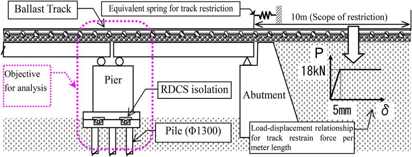
2    Luo

causes big response displacement on the struc-
ture, which adversely effects the running safety of
the trains supported by the structure.
   Therefore, how to secure the running safety of
a train for a seismic-isolation structure becomes
very important, which is an inherent problem
for railway structures different from others.
In order to solve this problem, in this paper,
the mechanism of seismic derailment, which

                                                                                                                  Downloaded from https://academic.oup.com/tse/advance-article/doi/10.1093/tse/tdab002/6185181 by guest on 14 May 2021
is quite different from the non-seismic one, is
expounded briefly, and the methodology for
                                                                                  (a)
seismic running safety assessment, which is
based on the characteristics of the train during an
earthquake, is introduced in detail. Then a new
type of seismic-isolation structure is proposed, in
which the foundation can convert the response
displacement in the lateral direction of track to
the longitudinal direction that has a less adverse
                                                                                  (b)
effect on the running safety of the train. The
foundation of this seismic-isolation structure
is composed of FPS (friction pendulum system)
slider, concave plate and guide ditch. To confirm
the behaviours of the proposed foundation, model
experiments were conducted under static push-
over loading and seismic loading with a vibration
table. Then 3D numerical simulation, which can
take the geometrical non-linearity into account,
was applied to explain the results of the model
experiments. Moreover, a real railway structure                                   (c)
installed with the new type foundation was taken
as the object for examination. As a result, it is      Fig. 1. Derailments of bullet trains due to earthquakes:
verified that the proposed structure can keep          (a) Chuetsu earthquake 2004 (Japan); (b) Jiaxian earth-
                                                       quake 2010 (Taiwan, China); (c) Kumamoto earthquake 2016
both the effects of the seismic-isolation and the
                                                       (Japan) (From Yahoo News)
running safety of the train.

                                                       except the contribution from Chen et al. [3].
2. Methodology for assessment of seismic               Therefore, both theoretical and experimental
running safety of trains                               studies of this specific issue are strongly required.
                                                          Until the Seismic Design Code for Railway Struc-
2.1 Safety limits for running vehicles
                                                       tures (the Railway Code, drawn up by Railway
Many serious derailment accidents occurred due         Technical Research Institute, Japan) [1] came into
to earthquakes in history. In particular, as shown     effect, there was no regulation contained in design
in Fig. 1, the derailment accidents of bullet trains   codes, such as the Eurocode [2], concerning the
caused by the Chuetsu earthquake 2004 (Japan),         seismic running safety of trains. At that time, the
the Jiaxian earthquake 2010 (Taiwan, China) and        purpose of structural seismic design was generally
the Kumamoto earthquake 2016 (Japan) have              focused on how to assure the safety of structures
given big impacts to society. In recent years, the     themselves. As to the running safety of a train,
seismic running safety of bullet trains has been       only the cases in which the track is deformed to
the object of great interest by researchers and        cause rail misalignment and/or folding at joints
railway industries in many countries, especially       were evaluated. This kind of assessment is con-
those in earthquake-prone regions, such as Japan       ducted under pseudo-dynamic conditions by com-
and China. However, quite limited numbers              paring the seismic deformation of structures to
of practical experiences and perfect evidences         the limit displacement of running safety for vehi-
are available for the researchers to support the       cles. However, besides the cases of track deforma-
comprehensive understanding of this issue,             tion, the running vehicles might also be dangerous
Transportation Safety and Environment, 2021, Vol. 0, No. 0   3

Safety limit of absolute displacement (mm)   600

                                             500               Shinkansen (Japanese bullet train)
                                                               Conventional railway
                                             400

                                             300
                                                                 Dangerous area

                                                                                                                                                                           Downloaded from https://academic.oup.com/tse/advance-article/doi/10.1093/tse/tdab002/6185181 by guest on 14 May 2021
                                             200

                                             100
                                                   Safe area
                                              0
                                               0.2 0.5         1.0      1.5     2.0      2.5        3.0
                                                                     Frequency (Hz)
                                                                                                             Fig. 3. Simplified analytical model of railway vehicle
Fig. 2. Relationships between safety-limit amplitude of
absolute displacement and frequency of sinusoidal waves
                                                                                                             the mechanism of derailment and/or overturning
under seismic vibration even though there is no                                                              of vehicles where the sophisticated numerical
obvious deformation occurred at the track. Actu-                                                             analysis technique and vast numbers of parame-
ally, the casualties shown in Fig. 1 just belong to                                                          ters were needed, which was another impractical
this kind of derailment. Therefore, how to assess                                                            factor for real seismic design.
the running safety of the train under vibration
displacement from the perspective of engineering
practice becomes significant.                                                                                2.2 Dynamic response analysis based on a
   At the early time (1997), to investigate the safety                                                       simplified model
limits of running vehicle some efforts have been                                                             Therefore, how to transfer the safety limits shown
made by Miyamoto, Ishida and Matsuo [4]. In those                                                            in Fig. 2 to the indexes for running safety assess-
studies, the safety limits of absolute displace-                                                             ment of vehicle combined in practical seismic
ment under the wheels, as shown in Fig. 2, were                                                              design of railway structures became a complicated
obtained by simulating the running of a vehicle                                                              task. To solve this problem, in 1999 I [5] down-
subjected to sinusoidal waves, based on a 58 DOF                                                             sized the rigorous analytical model to a simplified
vehicle/rail rigorous model. Although these efforts                                                          one, as shown in Fig. 3, which consists of few key
have indicated significant implication to under-                                                             parameters that can described the dominant char-
standing the dynamic behaviour of running vehi-                                                              acteristics of vehicle under vibration. By using this
cles, the results of such studies have not yet led                                                           model, the dynamic response of the vehicle under
to code-type provisions for running safety assess-                                                           sinusoidal oscillations can be analysed, and the
ment that can be applied to seismic design of rail-                                                          index for vehicle running safety assessment can
way structure, for two reasons:                                                                              be investigated based on the relationship between
 (i) The studies were based on the sinusoidal                                                                the responses due to sinusoidal waves and due to
     waves whose characteristics were different                                                              the random earthquake waves.
     from the random earthquake waves and the                                                                   In the case when the horizontal resistance force
     results of safety limit cannot be applied to seis-                                                      between the wheel flange and rail is large enough,
     mic design directly.                                                                                    the vehicle shown in Fig. 3 will oscillate around the
(ii) The absolute displacements caused by earth-                                                             centres of rotation O or O’ when it is at the onset of
     quakes are impossible obtained in a seismic                                                             rocking under the horizontal acceleration ü input
     design where relative displacements are cal-                                                            to the track. The governing equation of the rocking
     culated generally.                                                                                      motion is given by

  Moreover, the purpose of the studies by
Miyamoto, Ishida and Matsuo was to elucidate                                                                    I0 ϕ̈ + MüR ∗ cos(α ∗ − ϕ) + MgR ∗ sin(α ∗ − ϕ) = 0 (1)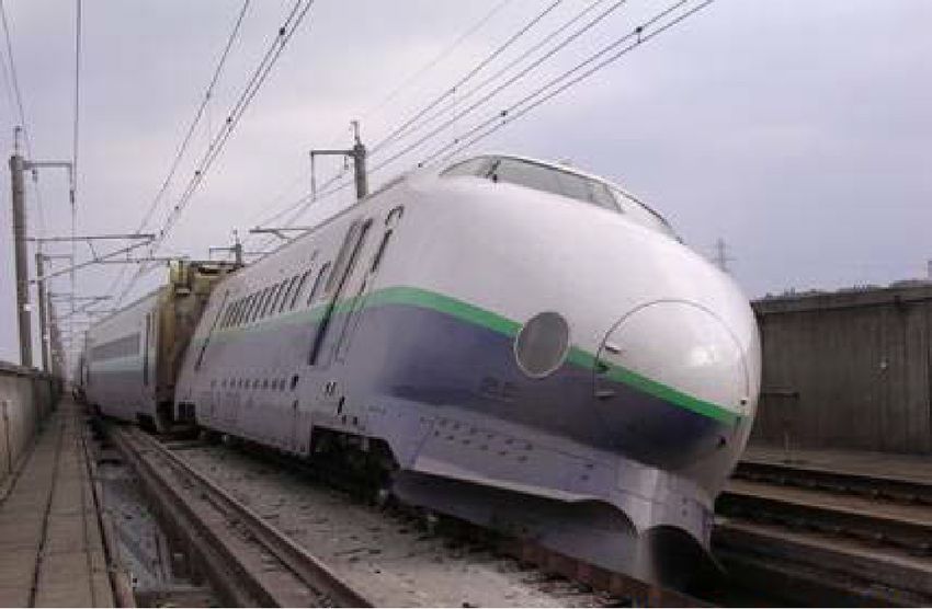
4     Luo

where I0 is the inertia moment of the vehicle about               1 in general cases:
its centre of gravity C; ϕ is the rocking angle of
vehicle; ϕ̈ is the angular acceleration of vehicle; M                                    A   gα ∗
is the mass of vehicle; g is the acceleration of grav-                                     =                          (5)
                                                                                         ω    p
ity; ü is the horizontal acceleration; R ∗ isthe effec-
tive radius for rotation of vehicle (R ∗ =            h∗2
                                                       g + b );
                                                            2
                                                                      Equation (5) expresses the minimum velocity
h∗g is the effective height of gravity centre of vehicle          (i.e. the critical velocity) needed to induce the ini-
that takes the effects of the overall spring system               tial overturning of the vehicle. This movement
into account (e.g. the increase in height is about                energy created by the critical velocity is equal to

                                                                                                                            Downloaded from https://academic.oup.com/tse/advance-article/doi/10.1093/tse/tdab002/6185181 by guest on 14 May 2021
20–25% for a conventional vehicle) [6]; b is the half             the critical potential energy needed for the initial
length of the span between the right/left wheel-                  overturning. The critical potential energy is rep-
rail contacting point; α ∗ is the angle between R ∗               resented by the rocking of the centre of gravity C
and the vertical direction (α ∗ ∼ = b/ h∗g ).                     of the vehicle to the highest position, right above
    Based on the assumptions that (i) the hori-                   point O in Fig. 3. The relationship between the
zontal acceleration is a half-cycle sine wave like                critical energy of the movement and the poten-
ü = −Asin(ωt + ψ); and (ii) the values of angles α ∗             tial energy can be expressed by the response spec-
andϕare small, Equation (1) then can be rewritten                 trum of velocity. Since this represents the max-
in the following form:                                            imum response values of velocity, it is in theory
                                                                  closely related to the maximum potential energy
      I0 ϕ̈ = −MgR ∗ (α ∗ − ϕ) + M Asin(ωt + ψ)R ∗          (2)   of the input wave as described below.
                                                                      In general, the variables used in the response
  Before the onset of rocking, Equation (2) can be                spectrum of a vibration system are assumed as
expressed as Asin(ωt + ψ) = gα ∗ and when t = 0                   the mass of the system M̄, the spring factor K̄ , the
the equation becomes A = gα ∗ / sin ψ. When the                   natural frequency ω̄, the maximum displacement
variables are substituted into Equation (2) the fol-              xmax , the displacement response spectrum Sd and
lowing expression is derived:                                     the velocity response spectrum Sv . Consequently,
                                                                  the maximum potential energy can be expressed
                                                                               ). As xmax = Sd and Sv ∼
                                                                             2
                                    sin(ωt + ψ)                   as 1/2(K̄xmax                         = ω̄Sd , the max-
               2       ∗    2
          ϕ̈ − p ϕ = α p                        −1          (3)   imum potential energy per unit mass is given by
                                       sin ψ

   After the variable p2 = MgR ∗ /I0 and the ini-                                   1                1
                                                                                      ( K̄ / M̄)Sd2 = Sv2             (6)
tial condition (ϕ(t=0) = 0, ϕ̇(t=0) = 0) are substituted                            2                2
into Equation (3), the solution for the differential
equation is obtained. Actually, the condition for                    From Equation (6), it is clearly understood that
the onset of overturning of the vehicle is that the               the velocity response spectrum is directly related
gravity centre of the vehicle rotates to the position             to the spectrum of the maximum potential energy.
just over the rotation centre O (ϕ = α ∗ ). After this            The index for the running safety assessment is
condition is substituted into the solution of Equa-               therefore liable to be determined by the velocity
tion (3), the solution can be simplified as a brief               response spectrum, which is the origin of the SI
form of Equation (4) [7–13]                                       (spectral intensity) index.


                                    2                           2.4 Adequacy verification of proposed index
                    A               ω
                        =       1+                          (4)
                   gα ∗             p                             To verify the adequacy of the proposed SI index for
                                                                  running safety assessment, a comparison study
where A/(gα ∗ ) is the normalized amplitude of                    was conducted between the assessment results
input acceleration and ω/ p is the normalized fre-                based on the SI index and based on the numeri-
quency of input wave.                                             cal simulation of running vehicles using the rigor-
                                                                  ous model with 58 DOF. Fig. 4 shows the assess-
                                                                  ment results for the Shinkansen (Japanese bullet
2.3 Index for running safety assessment
                                                                  train) vehicles corresponding to the two methods,
Furthermore, Equation (4) can be approximately                    under the earthquake motion. In the figure, the
expressed in the following form, because (ω/ p)2                 horizontal axis represents the equivalent natural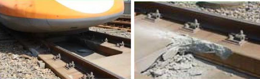
Transportation Safety and Environment, 2021, Vol. 0, No. 0   5

                                                                                                              Assessment
                                                                                                                Assessmentresults  by based
                                                                                                                              results
                                                                Safety limit of SI (SIL) for                  rigorous  numerical
                                                                                                                on rigorous       simulation
                                                                                                                             simulation
                                                                Shinkansen by rigorous                          underseismic
                                                                                                              under    earthquake
                                                                                                                              motionmotion
                                                 20000                                                                 Safe
                                                                numerical simulation
                                                                                                                       Critical
                                                 18000          under sinusoidal waves                                 Dangerous
                                                                                                                       Safe

                    Spectral intensity SI (mm)
                                                 16000
                                                                                                                       Safe
                                                                           Dangerous area
                                                 14000                                                                 Critical
                                                                                                                       Dangerous
                                                 12000                                                                 Safe
                                                                Assessment results
                                                               Assessment     resultsby code-type
                                                                                      based  on SIprovision
                                                                                                   index

                                                                                                                                                            Downloaded from https://academic.oup.com/tse/advance-article/doi/10.1093/tse/tdab002/6185181 by guest on 14 May 2021
                                                 10000          with index of
                                                               calculated      SI under
                                                                           under        seismicmotion
                                                                                   earthquake  motion                  Critical
                                                                                                                       Dangerous
                                                 8000
                                                 6000
                                                 4000
                                                 2000     Safe area
                                                    0
                                                         0.2    0.4       0.6      0.8       1.0       1.2    1.4        1.6       1.8         2.0
                                                                  Equivalent natural period of structure Teq (s)

Fig. 4. Assessment results of comparison study between proposed SI index and rigorous numerical simulation of running
vehicles under earthquake motion

period of railway structure (Teq ) that was calcu-                                             the position is on the curve) or dangerous (when
lated according to the seismic design code [1]. The                                            the position is above the curve) [14].
assessment results based on SI index were cal-                                                    Furthermore, to correspond to the 10 cases, the
culated corresponding to the Teq by inputting the                                              assessment results based on the rigorous numer-
earthquake motion on the ground surface into the                                               ical simulation are shown in the legend of the
SDOF system, which was modelled according to                                                   figure. Herein, the evaluated running states of
the seismic design code [1]. In another way, the                                               the vehicle are very close to those based on the
assessment results based on the rigorous numer-                                                method with response SI. Therefore, the good
ical simulation of running vehicles were achieved                                              coincidence between the results of the two differ-
under the response waves of the structure exerted                                              ent methods verifies the adequacy and accuracy
to the vehicles, which were obtained through the                                               of the proposed index, which satisfies the practi-
response analysis of the same SDOF system under                                                cal design.
the earthquake motion.
   Also in Fig. 4, a Shinkansen (Japanese bullet
train) vehicle was taken as the object for the com-                                            2.5 Application to seismic design of railway
parison study and its safety limit of SI (SIL ) was                                            structures
obtained based on the rigorous numerical sim-                                                  Although the proposed method for running safety
ulation. Moreover, to grasp the variation of the                                               assessment based on the SI index has been shown
assessment results corresponding to the Teq , the                                              to be appropriate for the seismic design of rail-
values of Teq ( = 0.5 s, 1.0 s and 1.5 s) were adopted                                         way structures, from the perspective of engineer-
to represent the types of structures with short,                                               ing practice it is still inconvenient that the val-
middle and long natural periods. To correspond to                                              ues of response SI and the limit SIL should be cal-
the values of Teq , 10 cases (three cases of 0.5 s, four                                       culated through dynamic analysis of structures
cases of 1.0 s, three cases of 1.5 s) with different                                           and vehicle running simulation. It is therefore
response waves caused by the earthquake motion                                                 necessary to provide a convenient code-type
were set for the assessment. The value of SI cor-                                              method for seismic design of structure. For quick
responding to each response wave was calcu-                                                    assessment of running safety, a nomogram (for
lated and plotted into the figure. According to the                                            which no calculation is needed) has been made,
relative relation between the position of response                                             as shown in Fig. 5. In this nomogram, the line
SI and the limit curve of SIL , the running state of                                           labelled safety limit (SIL ) is an envelop of a number
the vehicle can be judged as safe (when the posi-                                              of safety limits calculated using 11 typical earth-
tion of SI is under the curve of SIL ), critical (when                                         quake motions. These typical earthquake motions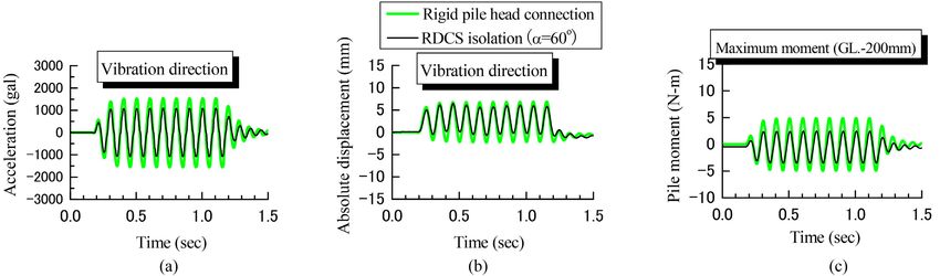
6    Luo

                                                        assessment of a train is focused on the exami-
                                                        nation of the lateral response displacement of
                                                        structure. Therefore, how to decrease the lat-
                                                        eral response displacement is significant to the
                                                        seismic-isolated railway structures.
                                                           In order to develop a seismic-isolation structure
                                                        that can reduce the lateral response displacement,
                                                        a new system called an RDCS (response-direction
                                                        conversion system) is proposed, and the concept

                                                                                                                Downloaded from https://academic.oup.com/tse/advance-article/doi/10.1093/tse/tdab002/6185181 by guest on 14 May 2021
                                                        of a seismic-isolation foundation with the system
                                                        is shown in Fig. 6. The system is set up inside
                                                        the footing, which is composed of the devices
                                                        with FPS (Friction Pendulum System) slider, con-
                  Teq                                   cave plate and guide ditch. Because of its supe-
                                                        rior effect of seismic isolation, the FPS has already
Fig. 5. Nomogram for running safety assessment corre-   been applied to many structures except railway
sponding to various ground classifications              structures. The reason to exclude railway struc-
                                                        ture is that the displacement due to the moving
                                                        slider is too large to cause train derailment. How-
were picked up from an earthquake database by
                                                        ever, in the proposed type of device, through the
considering the source property, epicentre dis-
                                                        pendulum sliding along the guide ditch, the lateral
tance, transmission behaviour, classification of
                                                        displacement due to the inertial force of pier can
surface ground and so on. Moreover, the curves
                                                        be converted to the longitudinal direction of track,
of response SI plotted in the nomogram are calcu-
                                                        which has a less adverse effect on the running
lated using the L1 design earthquake motions cor-
                                                        safety of the train. In this way, both seismic isola-
responding to various ground classifications [1]. In
                                                        tion and derailment prevention can be achieved.
seismic design, if the equivalent natural period Teq
                                                        Another characteristic of the system is that the
of the objective structure and the ground classifi-
                                                        residual displacement after earthquake is very
cation are known, the running state of the vehicle
                                                        small because the lower concave can make the
can be evaluated by comparing the quantities of
                                                        slider return to the original position under the self
response SI with SIL , conveniently [15, 16].
                                                        weight of the pier and the superstructure [17–19].
   Regarding to the assessment method for seis-
                                                           The direction of earthquake motion shown in
mic running safety of a train on a seismic-
                                                        Fig. 6 is perpendicular to the track, which is the
isolation structure, the SI index is also important
                                                        most adverse direction to running safety of the
and necessary, which can make the seismic design
                                                        train. Actually, during an earthquake the direc-
of structure efficient. An example for this kind of
                                                        tions of earthquake motion varies and most of
assessment is introduced in the following section.
                                                        them across the track diagonally, which is easy to
                                                        be converted than the perpendicular case.
3. Examination of a new type of                            A model device for the proposed system was
seismic-isolation structure based on model              made, as shown in Figs 7–9. Fig. 7 indicates the
experiments                                             lower plate set-up with four concaves and the
                                                        guide ditches with a conversion angle α. Fig. 8
3.1 Proposal for a response-direction conversion        shows the moveable upper plate at the pier side,
system                                                  and Fig. 9 shows the vertical cross section of
From the research results concerning run-               the concave. To ensure smooth sliding, the 0.75
ning safety of trains during earthquakes (for           mm clearance between the pendulum and the
example, Miyamoto, Ishida and Matsuo [4]), it is        guide ditch was adopted [20, 21].
understood that the running safety is influenced
dominantly by the horizontal absolute displace-
                                                        3.2 Horizontal cyclic loading tests
ment in lateral direction to track. According to
the Design Standards for Railway Structures and         To investigate the influence of the conversion
Commentary (Displacement Limits) (by the Railway        angle α on the response of structure, the horizon-
Technical Research Institute) [16], in seismic          tal cyclic loading was pushed or pulled on the pier,
design of railway structures, the running safety        as shown in Fig. 10. Also, another model with rigid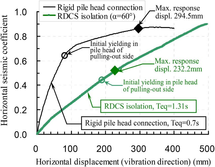
Transportation Safety and Environment, 2021, Vol. 0, No. 0       7

                                                                                  Earthquake motion
                                                                                  in lateral direction         Track

                                                                                                             Structure response
                         RDCS                                                                Pier            along longitudinal
                                                                                                             direction of track

                         Pier                                                             Relation between earthquake
                                                                                          motion and structural response

                                                                                                                                      Downloaded from https://academic.oup.com/tse/advance-article/doi/10.1093/tse/tdab002/6185181 by guest on 14 May 2021
                                               Before Earthquake
                                                                                                           Inertial force lateral
                           A           A                    Water stop                              ̔      to track due to pier

     Ground
                                             During Earthquake
                                                                                                              Diplacement
                                                                 Floating
                                                                                                              direction of slider

                                             After Earthquake
                                                                                        Guide ditch
                                                                                                      A-A Plane
  Earthquake motion in lateral direction             Lower concave plate

Fig. 6. Seismic-isolation foundation constituted by the proposed RDCS

               α                Guide ditch

                                          Concave

                                          Plate

Fig. 7. Lower concave plate (pile-head side)

                            α       Loading
                                                                    Fig. 10. Model foundation and loading device
                                    direction
          Sliding
         direction                                                  pile-head connection was prepared for compari-
                                                                    son. Both of the models had a similarity of 1:50.
                                                                       A total of five test cases were set corresponding
                                                                    to four kinds of RDCS isolation (α = 15◦ , 30◦ , 45◦ ,
                                                                    60◦ ) and one case of rigid pile-head connection.
Fig. 8. Upper movable plate (pier side)                             The results of the load-displacement relationship
                                                                    and the pile-moment distribution along the depth
  Friction pendulum                         Radius 75mm             are shown in Figs 11 and 12, respectively. From
                                                                    these figures, it is understood that even though
                                                                    the load level and pile moment increase as the
                                                                    conversion angle α increases, the pile moment
                          φ80mm                                     for the RDCS isolation is much smaller than that
                                                                    for rigid pile-head case. In Fig. 12 the maximum
Fig. 9. Vertical cross section of concave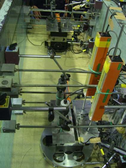
8    Luo

                                                                                                                Downloaded from https://academic.oup.com/tse/advance-article/doi/10.1093/tse/tdab002/6185181 by guest on 14 May 2021
Fig. 11. Load-displacement relationship

                                                       Fig. 13. Model structures and ground set-up on shaking
                                                       table

                                                       the bending moment and axial force of piles, the
                                                       acceleration and the displacement on the pier and
                                                       footing were taken as the objects for measuring.
                                                       Moreover, both of the directions longitudinal and
                                                       lateral to the vibration direction were considered
                                                       in the measurement.
                                                          To grasp the resonant behaviour (to find the
                                                       resonant frequency) of the model structures, the
                                                       sine waves of acceleration were input to the shak-
                                                       ing table, whose frequency varies from 20Hz to
                                                       5Hz. The wave number for each sine wave was
Fig. 12. Pile-moment distribution along depth          10, and the amplitudes were from 200 gal to 1000
                                                       gal. As a result, it was understood that the reso-
moment for the RDCS isolation (α = 60◦ ) is only one   nant frequency was 10Hz. Therefore, this reso-
fifth of that for rigid pile-head case, which proves   nant frequency was used for comparing the differ-
the obvious effect of seismic-isolation to reduce      ence between the responses corresponding to the
the inertial force [22–25]. Therefore, the case with   ‘rigid pile-head connection’ and the ‘RDCS isola-
conversion angle α = 60◦ was taken as the target       tion (α = 60◦ )’ as below.
for the deep investigation as below, which satisfied      Fig. 14 shows the response acceleration waves
both the requirements of converting seismic dis-       at the crest of the pier, which were measured
placement direction and reducing seismic inertial      under the maximum inertial force caused by the
force.                                                 input wave with 10 Hz and 800 gal. In Fig. 14a,
                                                       compared with the response acceleration 2100gal
                                                       (average value of the two side amplitudes) corre-
3.3 Shaking-table tests
                                                       sponding to the case of rigid pile-head connection,
Since the aforementioned static cyclical load-         the value to the case of RDCS isolation is less than
ing test excluded the effects of inertial force,       1600gal, about 25% lower. In contrast, as shown
the shaking-table test was needed. As shown in         in Fig. 14b in the direction perpendicular to the
Fig. 13, the pier models of pile head with RDCS        vibration direction, the acceleration correspond-
isolation connection (α = 60◦ ) and the rigid con-     ing to the case of RDCS isolation is several times
nection were set up in a same model ground on          of the value corresponding to the rigid pile-head
the shaking table. Regarding to the measurement,       connection. This phenomenon was cause by the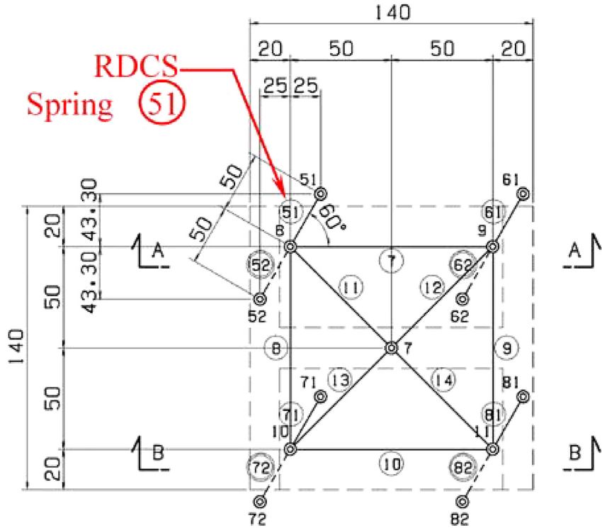
Transportation Safety and Environment, 2021, Vol. 0, No. 0          9

Acceleration (gal)   3000                                                                               3000

                                                                                   Acceleration (gal)
                     2000                                                                               2000
                     1000                                                                               1000
                                                      Rigid pile head connection
                        0                                                                                  0
                                                      RDCS isolation (a=60°)
                     -1000                                                                              -1000
                     -2000                                                                              -2000
                     -3000                                                                              -3000
                        0.0   0.5         1.0   1.5                                                         0.0   0.5         1.0   1.5
                                                                                                                    Time (sec)

                                                                                                                                          Downloaded from https://academic.oup.com/tse/advance-article/doi/10.1093/tse/tdab002/6185181 by guest on 14 May 2021
                                Time (sec)
                                    (a)                                                                                 (b)

Fig. 14. Response acceleration waves at crest of pier: (a) Vibration direction (lateral to track); (b) Perpendicular to vibration
direction (along track)

Fig. 15. Response displacement at crest of pier (vibration
direction)

                                                                   Fig. 17. Response of maximum pile moment (GL: 200 mm)

                                                                      The response of maximum pile moment at the
                                                                   depth of 200 mm is shown in Fig. 17. From the fig-
                                                                   ure it is understood that the moment correspond-
                                                                   ing to the case of RDCS isolation is less than half
                                                                   of the value corresponding to the rigid pile-head
                                                                   connection, which verifies the obvious effect of
                                                                   seismic-isolation [26, 27].

Fig. 16. Absolute displacement at crest of pier (vibration
direction)                                                         4. Numerical simulation for model
                                                                   experiments
conversion effect, which transferred the response                  To explain the situation of the model experi-
in vibration direction to the lateral direction par-               ments, a 3D dynamic numerical simulation, which
tially.                                                            can consider the geometrical non-linearity, was
   Fig. 15 presents the relative displacement at the               applied to the examination. An overall analytical
crest of pier along the vibration direction, while                 model for the pier with the RDCS isolation founda-
Fig. 16 shows the absolute displacement that was                   tion is shown in Fig. 18. The plane sectional view
obtained by integrating the acceleration shown in                  (E-E cross section in Fig. 18) of the footing analyt-
Fig. 14a. Both of the results show that the displace-              ical model is shown in Fig. 19, where the RDCS
ments corresponding to the case of RDCS isolation                  spring with conversion angle α (= 60◦ ) (for example
are about 20% to 30% smaller than the case of rigid                the No. ) is installed that can convert the lateral
pile-head connection, which means that the run-                    vibration of the track to the longitudinal direction.
ning safety for the case of RDCS isolation is better                  In this way, the purpose of securing running
than that for the rigid case.                                      safety of the train and reducing the inertial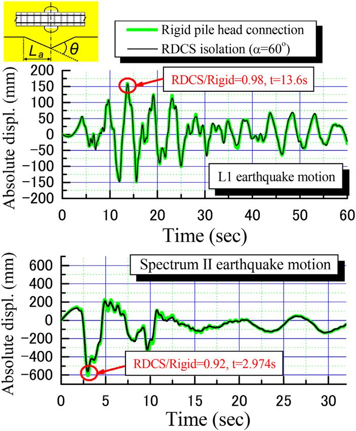
10    Luo

                                                                                                                                Downloaded from https://academic.oup.com/tse/advance-article/doi/10.1093/tse/tdab002/6185181 by guest on 14 May 2021
                                                               Fig. 19. Plane sectional view of footing (E-E cross section in
                                                               Fig. 18)

                                                               Fig. 20. Load-displacement relationship for RDCS spring

                                                               force of the super-structure can be realized syn-
                                                               chronously. The skeleton of the RDCS spring was
                                                               obtained by cyclic loading test, as shown in Fig. 20,
                                                               whose adequacy was already verified by compar-
                                                               ing with the analysis results.
                                                                  Furthermore, the members for the pier and pile
                                                               were modelled as elastic beam elements. As to
                                                               the model of subgrade reaction, the hyperbolic
                                                               type or bilinear type non-linearity was adopted.
                                                               The stiffness or resistance limits of subgrade were
                                                               determined based on the results of cyclic load-
                                                               ing test. Also, the damping factor with stiffness
                                                               dependency was adopted, which was set by fit-
                                                               ting to the first vibration mode. As to the damping
                                                               factors of material, 1% was set to the pier, pile or
                                                               isolation device, and 10% was set to the subgrade
                                                               spring.
                                                                  Fig. 21 shows the results for numerical simula-
                                                               tion of shaking-table test. Though there are some
Fig. 18. Analytical model for pier with RDCS isolation foun-
dation                                                         errors in the calculation, the basic behaviour and
Transportation Safety and Environment, 2021, Vol. 0, No. 0 11
Downloaded from https://academic.oup.com/tse/advance-article/doi/10.1093/tse/tdab002/6185181 by guest on 14 May 2021
Fig. 21. Numerical simulation results of response acceleration, absolute displacement and maximum pile moment: (a)
Response acceleration at crest of pier; (b) Response absolute displacement at crest of pier; (c) Response of maximum pile
moment
Table 1. Details of cross section for pile head
Pile head Rigid RDCS isolation
Connection
Cross section
Rebar D32-24(@156) D29-20(@156)
(mm2 ) 19 061 12 848
Ratio of rebar (%) 1.08 0.97
Hoop D22-1 Group@125 D19-1 Group @125
The details of cross sections for pile head are
shown in Table 1. These details were determined
through optimized design. As a result, the diam-
Fig. 22. Schematic illustration of bridge with ground condi-
eter (1300 mm) of the pile with the RDCS iso-
tion
lation decreased 15% compared with the diame-
ter (1500 mm) for the rigid pile-head connection.
overall shape are close to the results due to test The 15% decrease in diameter can cause a 35%
shown in Figs 14 to 17. decrease in the amount of steel reinforcement,
which reflects an obvious economical effect to the
construction cost in engineering practice.
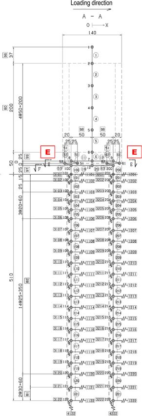
5. Examination of real structure based on For the objective bridge, the procedure for
analysis examining the seismic-isolation effect and the
running safety of the train is described below:
In design practice, the construction cost of pile
foundation is generally dependent on the cross- (i) The superstructure and the foundation are
section area of the pile body when the length of modelled as an overall structure. Then, for
pile is fixed. In order to grasp the influence due grasping the seismic performance of the struc-
to the RDCS isolation connection on the seismic ture, the pushover analysis is conducted to
design of pile foundation, a real railway bridge obtain the load-displacement relationship.
shown in Fig. 22, whose pile head was connection (ii) The response acceleration and displacement
by rigid or RDCS isolation, was taken as the object of structure are calculated by inputting the L1
for examination of the seismic-isolation effect and and L2 earthquake motions stipulated in the
the running safety of the train. seismic design code [1].12 Luo
Downloaded from https://academic.oup.com/tse/advance-article/doi/10.1093/tse/tdab002/6185181 by guest on 14 May 2021
Fig. 23. Non-linear behaviour for beam element
Fig. 25. Load-displacement relationship at crest of pier
(iii) The damage level of pile member and the than the value for rigid pile-head connection. By
seismic performance of structure are assessed plotting the maximum response displacements,
based on the results from the pushover analy- which were calculated through dynamic analysis,
sis and the dynamic analysis. on the load-displacement curve, the damage level
(iv) The running safety of the train is assessed by of the pile members was assessed. The results
using the indexes of the angular rotation and show that, though in both cases the members of
the SI stipulated in the design code [16]. pile head in pulling-out side reached damage level
2, the safety margin for the case of RDCS isolation
The members of pier and pile were modelled was larger than that in the rigid pile-head connec-
as beam elements, whose Non-linear behaviour is tion case.
shown in Fig. 23. Furthermore, as shown in Fig. 24, Regarding the running safety assessment of
the track restriction force was taken into account trains during earthquakes, there are two items
in the 3D dynamic analysis. related to the lateral displacement of structure
Fig. 25 presents the load-displacement relation- should be assessed according to the design code
ships at crest of pier corresponding to the cases (displacement limits) [16]. One is the angular
of rigid pile-head connection and the RDCS iso- rotation of track that is caused by the absolute
lation, which were calculated by pushover analy- displacement at crest of pier. The other is the
sis. Both of the cases show that the initial yield- vibration displacement that occurs on the track
ing of pile members occurred in the pile head of even though there is no deformation to the track.
pulling-out side. The yielding seismic coefficient For the former item, the assessment is conducted
for the RDCS isolation is about one third smaller by comparing the differential displacement of
Fig. 24. Analytical model for calculation of track-restriction forceTransportation Safety and Environment, 2021, Vol. 0, No. 0 13
Downloaded from https://academic.oup.com/tse/advance-article/doi/10.1093/tse/tdab002/6185181 by guest on 14 May 2021
Fig. 27. Comparison of SI for vibration-displacement assess-
ment
6. Conclusions
Fig. 26. Comparison of absolute displacement for angular
rotation assessment In this study, in order to propose a new type of
seismic-isolation system, the RDCS, the related
problems like mechanism of seismic derailment
of the train and the code-type methodology
structures with the limit values [28]. For the latter for running safety assessment of the train has
item, because of the different patterns of derail- been expounded in full detail. Since the abso-
ment corresponding to different frequency com- lute displacement caused by earthquake cannot
ponents of the input waves, the SI that evaluates be obtained in a seismic design of railway struc-
the total energy of the input wave is taken as the ture, the SI is the appropriate index for running
index for assessment (Luo, X. [14]). safety assessment of the train from the perspec-
According to the design code (displacement tive of energy equilibrium.
limits) [16], the level-I (L1) design earthquake As to the proposed seismic-isolation system
motion should be used for the running safety call RDCS, the merit of this kind of isolation device
assessment of a train. By using the response accel- is that the response displacement in the lateral
erations at the crest of pier that were calculated direction of track can be converted to the longi-
from dynamic analysis based on L1 earthquake tudinal direction, which has a less adverse effect
motion, the absolute displacement and the SI on the running safety of the train during an earth-
were calculated. Fig. 26 shows the results of the quake.
absolute displacement, and Fig. 27 presents the In order to confirm the behaviours of the pro-
results of the SI. In Fig. 26, the absolute displace- posed isolation system, the model experiments
ment corresponding to the RDCS isolation is about were conducted under statically and dynamically
10% smaller than that corresponding to the rigid loading. Also, static and dynamic 3D numerical
pile-head connection. In Fig. 27, the SI values cor- simulation, which can take the geometrical non-
responding to the RDCS isolation are about 20% linearity into account, was applied to explain the
smaller than those due to the rigid pile-head con- situation of the model experiments.
nection. From the perspective of running safety of To grasp the influence due to the RDCS isola-
the train, therefore, the RDCS isolation connection tion on the seismic design of pile foundation, a
is also better than the rigid pile-head connection. real railway bridge was taken as the object for ana-
Therefore, either the construction cost or the run- lytical examination. After various calculations by
ning safety of the train, the proposed pile foun- using the L1 and L2 design earthquake motions, it
dation with the RDCS isolation is better than the is understood that the RDCS isolation is suitable
rigid connection in the pile head [29, 30]. to railway structures, which can satisfy the both14 Luo
necessaries for the seismic-isolation and the run- displacements during earthquakes. RTRI Rep 2006; 20:
ning safety of the train during an earthquake. 1219–24.
16. Railway Technical Research Institute. Design Standards for
Regarding to the issues related to the applica-
Railway Structures and Commentary (Displacement Limits),
tion of the RDCS isolation in future, the behaviour Drawn up by Railway Technical Research Institute, Pub-
of the prototype size model, as well as the lished by Maruzen; Tokyo, Japan, 2006.
endurance or cost of the devices and materials 17. Zayas VA, Eeri M, Low SS et al. A simple pendulum tech-
should be examined further. nique for achieving seismic isolation. J Earthq Spectra 1990;
6:2317–33.
Conflict of interest statement. None declared. 18. Olariu I, Sarbu D, Orariu F et al. Seismic protection using
kinematic-energy dissipating base isolation system. In: Pro-
Downloaded from https://academic.oup.com/tse/advance-article/doi/10.1093/tse/tdab002/6185181 by guest on 14 May 2021
REFERENCES ceedings of the 12th European Conference on Earthquake Engineer-
ing, London, UK, 2002, No. 514.
1. Railway Technical Research Institute. Design Standards for
19. Muhammet Y, Sevket A, Ahmet CA. Comparison of the
Railway Structures and Commentary (Seismic Design), Drawn
dynamic responses of Gülburnu highway bridge using sin-
up by Railway Technical Research Institute, Published by
gle and triple concave friction pendulums. J Earthq Struct
Maruzen; Tokyo, Japan, 1999.
2014; 7:4511–25.
2. EN 1998: Eurocode 8: Design of Structures for Earthquake Resis-
20. Luo X, Hamada Y. Study on seismic performance of struc-
tance. Brussels: European Committee for Standardization,
tures with different pile-head-join. In: Proceedings of the
1998.
40th Japan National Conference on Geotechnical Engineering,
3. Chen LK, Jiang LZ, Qin HX et al. Nonlinear seismic assess-
Hakodate-city, Japan, 2005, No. 860.
ment of isolated high-speed railway bridge subjected to
21. Luo X, Hamada Y, Mizuno N et al. Basic model experiments
near-fault earthquake scenarios. Struct Infrastruct Eng 2019;
on seismic-isolation foundation considering running safety
15:1529–47.
of trains during earthquakes. In: Proceedings of the 41st Japan
4. Miyamoto T, Ishida H, Matsuo M. Running safety of rail-
National Conference on Geotechnical Engineering, Kagoshima-
way vehicle as earthquakes occur. Q Rep RTRI 1997; 38:
city, Japan, 2006, No. 945.
3117–22.
22. Luo X, Miyamoto T, Imamura T. Study on influence of
5. Luo X, Nishimura A. A study on running safety of rail-
seismic-isolation foundation upon running safety of train
way vehicles undergoing track vibration due to earth-
during earthquakes. In: The 12th Japan Earthquake Engineer-
quakes. In: Collected Papers of Joint Symposium on Japan
ing Symposium, Tokyo, Japan, 2006, No. 230.
Railway Technology (J-RAIL’99), Kawasaki-city, Japan, 1999,
23. Luo X, Dewa T, Imamura T et al. Model experiments on
337–40.
seismic-isolation foundation with ability to control direc-
6. Kunieda M. Theoretical study on the mechanics of over-
tion of response. In: Proceedings of the 42nd Japan National Con-
turning of railway rolling stock. RTRI Rep 1972; 793:
ference on Geotechnical Engineering, Nagoya-city, Japan, 2007,
1–15.
No. 640.
7. Ishiyama Y. Criteria for overturning of bodies by earthquake
24. Luo X, Dewa T, Imamura T et al. Model experiments on
excitation. T Arch Inst Jpn 1982; 317:1–12.
seismic-isolation foundation avoiding adversely affecting
8. Luo X, Nishimura A. A practical assessment method for run-
running safety of train during earthquakes. In: Proceedings
ning safety of train against seismic displacement. In: Pro-
of the 62nd JSCE Annual Meeting, Hiroshima-city, Japan, 2007,
ceedings of the 26th JSCE Earthquake Engineering Symposium,
No. I-336.
Tokyo, Japan, 2001, 1193–6.
25. Luo X, Kawanishi T, Ohta T. Model experiments on seismic-
9. Luo X. A simplified method for running safety assessment
isolation foundation with a little residual displacement and
of railway vehicles during earthquakes based on the spec-
ability to change direction of response. In: Proceedings of
tral intensity. RTRI Rep 2002; 16:331–36.
the 43rd Japan National Conference on Geotechnical Engineering,
10. Luo X. A code-type provision for running safety assessment
Hiroshima-city, Japan, 2008, No. 587.
of train undergone earthquake motions. In: Proceedings of the
26. Luo X, Kawanishi T. Model experiments on seismic-
12th European Conference on Earthquake Engineering, London,
isolation foundation with a little residual displacement and
U.K., 2002, No. 462.
ability to change direction of response. In: Proceedings of
11. Luo X. Study on running safety assessment of trains on spe-
the 44th Japan National Conference on Geotechnical Engineering,
cial ground during earthquakes. In: Proceedings of the 38th
Yokohama-city, Japan, 2009, No. 593.
Japan National Conference on Geotechnical Engineering, Akita-
27. Luo X, Kawanishi T. Research of seismic-isolation founda-
city, Japan, 2003, No. 4.
tion with slider system considering running safety of trains.
12. Luo X. A practical methodology for running safety assess-
In: Proceedings of the Annual Meeting 2009 of Japan Association
ment of trains during earthquakes based on spectral inten-
for Earthquake Engineering, Tokyo, Japan, 2009, 156–7.
sity. In: Proceedings of the IABSE Symposium Antwerp, Antwerp,
28. Sogabe M, Miyamoto T, Matsuhashi K et al. Evaluation
Belgium, 2003, 322–3.
method for differential displacement of structures with
13. Luo X. Study on indices of running-safety assessment of
considering the influence of horizontal vibrational displace-
trains against lateral seismic displacements. In: Proceedings
ment. RTRI Rep 2006; 20:5–10.
of the 39th Japan National Conference on Geotechnical Engineer-
29. Luo X, Kawanishi T. Study on seismic-isolation foundation
ing, Niigata-city, Japan, 2004, No. 6.
with ability to convert response direction based on sliding
14. Luo X. Study on methodology for running safety assessment
isolator system. J Jpn Soc Civ Eng Ser A1 2010; 66:1105–14.
of trains in seismic design of railway structures. J Soil Dyn
30. Luo X. Analytical study on seismic-isolation bearing with
Earthq Eng 2005; 25:279–91.
less effects on running safety of train. In: Proceedings of
15. Luo X, Miyamoto T. A method for running safety assess-
the 16th Railway Engineering Symposium, Tokyo, Japan, 2012,
ment of railway vehicles against structural vibrating
125–32.You can also read