CEILING-MOUNTED MONORAIL - Assembly and Operation Instruction Manual ANCHOR TRACK SYSTEM
←
→
Page content transcription
If your browser does not render page correctly, please read the page content below

CEILING-MOUNTED MONORAIL
ANCHOR TRACK™ SYSTEM
Assembly and Operation Instruction Manual

  This manual is for various mounting types and
         plain and trussed track profiles.

ISO 9001:2015 Registered
Manual 103-0075                                   Effective Date: March 2021
RIGID LIFELINES CONDITIONS OF USE AND WARNING STATEMENT
1. Read, understand, and follow the manual, assembly drawings, and warnings provided with your system before
beginning installation.
2. This manual, and any other instructions, must be provided to the users of this equipment. The user must understand the
equipment’s proper use and limitations.
3. A fall event can result in serious injury or death. This equipment, when used properly, reduces the chances of those
outcomes.
4. Always perform a hazard analysis before use that will identify impact hazards, swing hazards, or any other hazards that
may exist. Address and correct all hazards before use.
5. Always have a written rescue plan that defines who will rescue a fallen worker, what equipment will be used, and
optimum rescue response time. If the same system will be used for rescue, a minimum of a two-man system must be
specified.
6. Follow all current requirements of ANSI Z359 (or CSA Z259 in Canada).
7. Each component and system must be employed and maintained in accordance with all OSHA and ANSI standards.
8. Per OSHA and ANSI (or CSA Z259 in Canada) requirements, designate a competent person who can fulfill obligations of
all regulations.
9. Note the maximum number of users and weight capacities are listed on a label on the system. Exceeding the capacities
listed on this label can result in serious injury or death.
10. Always check for overhead hazards, such as power lines, trees, overhead structures, or walls, before using or moving
system.
11. Any component replacement, addition, or change to any portion of the system must be evaluated by a Qualified Person
as defined by OSHA standards.
12. Never use this system for material handling.
13. Never use the system with scaffolding.
14. Never use the system alone without a monitor. Use the buddy system when using fall protection. The monitor, or
“buddy,” does not need to be attached to the system, but just nearby supervising.
15. Consult with a qualified person for minimum fitness requirements for workers. Determination of minimum fitness levels
of workers prior to use of system is by others.
16. For mobile systems—It is the responsibility of the user and their management’s Competent Person to determine that the
system’s base is level, the masts are plumb, and that the entire, leveled system is stable before every use.
17. For movable track systems—Always use the system in work spaces that allow you to move the system’s runway as close
as possible to the center of the work area.
18. Before each use, inspect the system for bent, broken, cracked, or missing components.
19. A competent person must thoroughly inspect the system annually and after each fall event.
20. There should never be any type of loading past the end stops for any reason.
21. When connecting track sections on runway systems, track splice and truss splice plates are required. For trussed track,
splice centers must be within maximum 48 inches of the hanger support centers unless otherwise specified. For plain
track, splice track centers must be within maximum18 inches of the hanger support centers unless otherwise specified.
22. Systems with flush clamp hangers do not require sway bracing. However, all systems mounted to the ceiling must be
laterally and longitudinally braced with sway bracing.
i Rigid Lifelines® Ceiling-Mounted Monorail Anchor Track™ System | 1-800-869-2080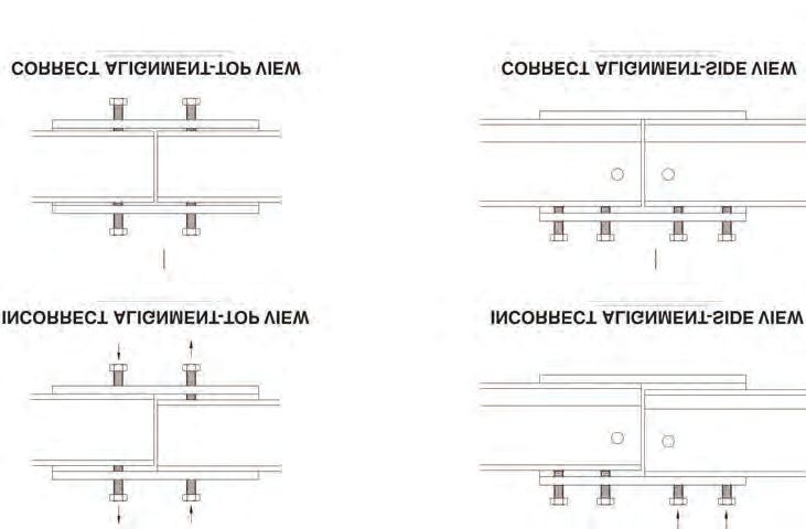
RIGID LIFELINES CONDITIONS OF USE AND WARNING STATEMENT
23.   If supplied, all drive systems are chain driven, and as a result, will experience some backlash in the drive assembly.
      Although backlash cannot be fully eliminated, it can be reduced by tightening the drive chain. Torque limiters, if
      supplied, require special attention. Most drive issues result from improper torque limiter adjustment or installation.
24.   It is the customer’s responsibility to confirm that the system and components will work in and are acceptable for their
      specific application and environment.
25.   For foundation-mounted systems, bracing is not required for non-seismic applications. However, if any sway is
      perceived as undesirable, lateral bracing can be installed to the system by others. To achieve desired rigidity for a
      specific application, Rigid Lifelines® recommends consulting a professional engineer in your area to satisfy all codes and
      ordinances. For foundation-mounted systems, chemical anchor bolts supplied by others are required and must provide
      approximately 7000-pound pull-out force. More accurate pull-out forces are available upon request.
26.   Engineering of any attachment points must be done by others.
27.   Component appearances and dimensions shown are approximate and subject to change without notice. All catalog
      dimensions are developed using standard components for the spans and capacities. Substitution of optional trolleys or
      other components will affect certain dimensions.
28.   All Rigid Lifelines Anchor Track™ Systems meet or exceed OSHA and ANSI requirements.
29.   Never load the track at an angle greater than specified in the system’s user manual.
30.   Never use the system with the attachment point below the D-Ring of the harness.
31.   Only the following self-retracting lanyard (SRL) design specifications are acceptable for use on Rigid Lifelines Anchor
      Track Systems:
      a)   900-pound maximum average arresting force (MAAF)
      b)   4.5 feet-per-second lock up speed
      c)   Disk or drum braking mechanism
      d)   Wire rope SRL’s can be used for indoor or outdoor applications
      e)   Fabric or web SRL’s can be used only for indoor applications
32.   The following energy-absorbing lanyards are not acceptable: rip-stitch packs, shock packs, or stretchable energy.
33.   Choose the shortest length SRL that will allow the workers to perform their job function. The shortest length SRL will
      reduce total fall distance by reducing “cable cinching” on the internal SRL pulley. Fabric lanyards stretch under load. The
      longer the lanyard, the longer the stretch.
34.   Never use metallic cables or metallic SRL’s around electrical power sources.
35.   Only an ANSI (or CSA in Canada) full-body harness is acceptable for use on Rigid Lifelines Anchor Track Systems.
36.   Never use body belts on this system.
37.   Never add additional carabiners, D-Rings, shackles, or connecting hardware to this system.
38.   On Traveling Bridge Anchor Track Systems, always position the bridge(s) directly overhead of worker(s) at all times.
39.   If a boom is provided, never apply a lateral load at the boom tip.
40.   Never deviate from the above unless you have written permission and authorization from Rigid Lifelines.

                                  1-800-869-2080 | Rigid Lifelines® Ceiling-Mounted Monorail Anchor Track™ System                   ii
Follow the Inspection Checklists in this manual: review         NEVER EXCEED 30 DEGREES OFF-PLUMB
      the first checklist before each use and the second              (OFF-CENTER) LOADING.
      checklist for after a fall event and annual inspections.

                   This system must be used with an ANSI-rated self-retracting lanyard (SRL).
                   If the system is used outdoors, it is highly recommended that a steel cable SRL with
                   heavy-duty housing be used for improved durability against UV radiation and moisture.
                   A web strap ANSI-rated SRL may be acceptable for use as long as a Competent Person has
                   evaluated the situation and determined that there are no factors present that can have an
                   immediate negative impact on the integrity of the SRL’s webbing material AND that the
                   Competent Person inspects the condition of the SRL’s webbing and housing prior to each use.

                                   Completely retracting the SRL after each use (e.g., using a
                                   retrieval tagline) is essential: otherwise, the SRL’s internal
                                   spring remains under tension, and it quickly loses its ability
                                   to properly arrest a freefall.
                                   Retrieval taglines must never be used as an anchorage;
                                   doing so could result in serious injury or death.

iii    Rigid Lifelines® Ceiling-Mounted Monorail Anchor Track™ System | 1-800-869-2080
TABLE OF CONTENTS
CONDITIONS OF USE AND WARNINGS STATEMENT...................................................................................................i-iii
SYSTEM APPLICATIONS......................................................................................................................................................2
STANDARDS AND COMPLIANCE.......................................................................................................................................2
REQUIRED TRAINING...........................................................................................................................................................2
ASSEMBLY INSTRUCTIONS.................................................................................................................................................3
1. Equipment Needed for Assembly.................................................................................................................................3
2. Inventory.....................................................................................................................................................................3
REQUIRED BRACING.........................................................................................................................................................3-4
ATTACHING THE TRACK SPLICE TO THE TRACK SECTIONS......................................................................... 4-6
CEILING-MOUNTED PLAIN TRACK HANGING OPTIONS................................................................................. 6
1. Flush-Parallel Mount..................................................................................................................................................6-7
2. Flush-Cross Mount....................................................................................................................................................8-9
3. Drop Rod................................................................................................................................................................9-10
4. Sloped Drop Rod...................................................................................................................................................11-12
CEILING-MOUNTED TRUSSED TRACK HANGING OPTIONS.......................................................................... 13
1. Flush-Parallel Mount..............................................................................................................................................13-14
2. Flush-Cross Mount................................................................................................................................................14-15
3. Drop Rod..............................................................................................................................................................16-17
4. Sloped Drop Rod...................................................................................................................................................18-19
FINAL ASSEMBLY...............................................................................................................................................................20
RUNWAY ALIGNMENT TOLERANCE................................................................................................................................21
INTERMEDIATE BUMPER INSTALLATION (IF SUPPLIED)..............................................................................................22
MAINTENANCE...................................................................................................................................................................23
LABELING............................................................................................................................................................................24
CEILING-MOUNTED MONORAIL INSPECTION CHECKLISTS.........................................................................................25
Ceiling-Mounted Monorail Anchor Track™ System...........................................................................................................25
Annual Anchor Track™ System........................................................................................................................................26
PRODUCT WARRANTY COVERAGE..................................................................................................................................27
ABOUT RIGID LIFELINES®................................................................................................................................BACK COVER
1-800-869-2080 | Rigid Lifelines® Ceiling-Mounted Monorail Anchor Track™ System 1SYSTEM APPLICATIONS COVERAGE AREA
The Ceiling-Mounted Monorail Anchor Track™ System is used for fall
protection applications. This fall protection system is labeled with
maximum number of users and maximum arresting force; follow all
limitations as noted on system label. Each user must attach to this system
using a personal fall arrest system. Monorail systems provide a rectangular
area of coverage, allowing workers to move up to 30 degrees off-plumb.
Off-plumb loading is not permitted past runway end stops.
STANDARDS AND COMPLIANCE
Please refer to local, state, and federal (OSHA) requirements governing occupational safety for additional information
regarding personal fall arrest systems. The Ceiling-Mounted Monorail Anchor Track System meets or exceeds the requirements
set forth in OSHA 1910, OSHA 1926, and ANSI Z359.
REQUIRED TRAINING
This system is intended to be used by people who are trained in its correct application and use. It is the responsibility of the
users and the users’ management to assure that they are familiar with these instructions and are trained in the correct use
and care of this equipment. Authorized users must also be aware of the operating characteristics, application limits, and the
consequences of improper use, which can result in serious injury or death.
Every application of fall protection must be part of a comprehensive managed fall protection program. Each program must
include, but is not limited to:
• Hazard analysis
• Authorized person training
• Competent person implementation
• Rescue procedures
• Rescue training
The above list is not a comprehensive list. Specific applications may need to include additional items, such as administrative
controls or engineered controls. A Qualified Fall Protection Engineer or OSHA Qualified Person should review the
comprehensive managed fall protection program to ensure that it is adequate for your specific application. For more
information on how to set up a proper Fall Protection Program within your facility, follow ANSI Z359.2 Minimum Requirements
for a Comprehensive Managed Fall Protection Program, which is available at: www.assp.org.
2 Rigid Lifelines® Ceiling-Mounted Monorail Anchor Track™ System | 1-800-869-2080ASSEMBLY INSTRUCTIONS
1. Equipment Needed for Assembly
a) This manual
b) Applicable safety equipment for workers’ use during assembly, such as hard hats, safety shoes, etc.
c) Telescoping fork truck or crane (minimum lifting height: determined by installed system height; minimum capacity:
4,000 pounds)
d) Man lift/cherry picker (minimum height: determined by installed system height)
e) Measuring tape
f) Torque wrench
g) Lifting straps
h) Two six-inch by six-inch (or larger) wood blocks
i) Long carpenter’s level or laser level
j) Wrench/Sockets sizes: 3/4 inch, 15/16 inch, and 1-1/8 inch
k) A spacious, level area for assembly (e.g., parking lot)
l) A way to mark hanger locations, such as a permanent marker
m ) FA-MT-ASSEMBLY SHEET 1 OF 2, hereafter referred to as Ceiling-Mounted Monorail Assembly Drawing, will be
included as a separate document.
n) FA-MT-ASSEMBLY SHEET 2 OF 2, hereafter referred to as Ceiling-Mounted Monorail Label Placement Drawing, will
be included as a separate document.
o) The Anchor Trolley™ User Instruction Manual (Manual 103-0054), which is packaged with the Anchor Trolley, will be
included as a separate document.
2. Inventory
a) Open all bundles and confirm that all components are accounted for: see Building Materials Description located in
the top right corner of the Ceiling-Mounted Monorail Assembly Drawing. Note that the quantity of components in
an assembly are multiplied by the number of the assemblies.
b) Check for damage to components that may have occurred during shipping.
REQUIRED BRACING
Refer to Figure 1 for Steps 1 Through 7
NOTE: Flush-mount applications do not require bracing.
1. Sway bracing is required for all ceiling-mounted monorail systems that use drop rods. Sway bracing resists lateral fall
arrest forces, reduces lateral stresses on drop rods, and prevents system hardware from loosening and wear due to cyclic
loading.
2. Sway bracing is required at each end of the system in both directions (laterally and longitudinally).
3. Intermediate bracing is required on one side of the monorail at each hanger assembly closest to the track splices (if
required).
4. Rigid Lifelines is not liable for design of supporting structures or attachments of system hangers and/or bracing to
supporting structures. However, Rigid Lifelines can provide the hangers and sway bracing pipe for the bracing. All
supporting structures must be designed by a qualified person using all applicable local, state, and national code
requirements.
1-800-869-2080 | Rigid Lifelines® Ceiling-Mounted Monorail Anchor Track™ System 35. Support structures of structural steel must be designed, fabricated, and/or erected per requirements of “American
Institute of Steel Construction” (AISC). Special attention must be given to the requirements for impact and deflection
forces to maintain the integrity of the complete building structure and system. The qualified person is liable for the final
design.
6. All bracing shown in Figure 1 is to be used as a guide only and should be considered as the minimum requirements for
the ceiling-mounted monorail systems that use drop rods. Minimum pipe diameter is one inch for systems with drop
rods. Systems with drop rods longer than 12 inches require special design attention by a qualified person.
7. Other bracing materials and designs may be acceptable if they are designed by a qualified person.
a ) NOTE: A qualified person must determine proper brace tube strength before installation.
Figure 1
Top View Typically, monorail bracing is
Bracing Support Centers Support Centers at each end at one side of the
monorail at each hanger point.
Bracing
Bracing
Bracing
Bracing
Bracing Bracing
Monorail End View
Bracing
Drop
Bracing
Rods Support Structure
Side View
Pipe Brace
Bracing Support Centers Support Centers Bracing
Support Structure Support Structure is provided by
others. Typically, pipe brace goes both
Bracing
Drop Rods ways at corners.
Pipe Brace Pipe Brace
Typically, pipe brace goes both ways at
Track Splice corners.
Monorail
ATTACHING THE TRACK SPLICE TO THE TRACK SECTIONS
Refer to Figure 2 and Figure 3 for Steps 1 Through 9
1. Depending on the existing ceiling structure, span, and track series, track splices are required. If you purchased a system
that requires a track splice, follow the steps below to attach the track splice to the track sections. If your system doesn’t
require a track splice, proceed to Ceiling-Mounted Plain Track Hanger Options on page 5 or Ceiling-Mounted
Trussed Track Hanger Options on page 12.
2. Per Figure 2, the track splice joint (B) comes assembled using a sleeve with a total of eight set screws threaded into the
top and both sides.
3. Per Figure 2, slide the track splice joint (B) over the end of the first track section, then butt the second track section
against the first. Center the track splice joint (B) over both track section ends.
4. Per Figure 2, securely tighten the top two center set screws to push the track sections against the base of the track
splice joint (B) until both track section bottom surfaces are aligned. Adjust both sets of side set screws so that the track
slots are aligned and there is a smooth transition from one track section to the other.
5. Per Figure 2, after you properly align the track sections (see Figure 3 on page 4), tighten the top set screws first before
tightening the side set screws. Do not over-tighten set screws.
4 Rigid Lifelines® Ceiling-Mounted Monorail Anchor Track™ System | 1-800-869-20806. Per Figure 2, bolt the track splice plates (B1) to the top of the track sections on both sides using nuts (B3) and bolts (B2).
Torque the nuts (B3) to 51 foot-pounds.
NOTE: The track splice plates (B1), nuts (B3), and bolts (B2) are only required for trussed track.
Figure 2
Item Description
B1 B
C Track Sections
B Track Splice Joint
B3 C
B1 Track Splice Plate
B2 1/2-inch Hex Head Bolt
B1
C B3 1/2-inch Hex Locknut
B2
7. Per Figure 3, the track splice joint (B) must be properly aligned with the track sections.
Figure 3
Top View of Incorrect Alignment Side View of Incorrect Alignment
Top View of Correct Alignment Side View of Correct Alignment
8. If you ordered a multiple track system, repeat steps 2. through 7. to attach the remaining track splice(s) to the track
sections.
1-800-869-2080 | Rigid Lifelines® Ceiling-Mounted Monorail Anchor Track™ System 59. Refer to Detail “B” below for an illustration of the properly attached track splice to the track sections.
Detail “B” (Track Splice to Track Sections)
B1
B2 B3
Item Description
C Track Sections
B Track Splice Joint
B1 Track Splice Plate
B2 1/2-inch Hex Head Bolt
B3 1/2-inch Hex Locknut
C
B
C
CEILING-MOUNTED PLAIN TRACK HANGING OPTIONS
1. Flush-Parallel Mount
Refer to Figure 4 for Steps A Through Q
a) Ensure that track splices (B in Ceiling-Mounted Monorail Assembly Drawing), if supplied, have been installed per
ATTACHING THE TRACK SPLICE TO THE TRACK SECTIONS on pages 3-5.
b) Using a measuring tape and a permanent marker, measure and mark 12 inches in from each end of the track for
standard overhang. Also measure and mark your support spacing requirements. These locations are where the
hanger kits (A in Ceiling-Mounted Monorail Assembly Drawing) should be installed on the track.
NOTE: 12-inch overhang is standard. Refer to your Final Fabrication Drawing for correct overhang lengths and
support spacing for your specific system.
c) Per Figure 4, slide all of the hanger brackets (7) onto the track so that the welded top plate on the hanger bracket
(7) is facing up away from the track.
d) Per Figure 4, slide an end hanger bracket (7) onto the marked spot on the track so that the welded top plate on
the hanger bracket (7) is facing up away from the track.
e) Per Figure 4, securely tighten the side set screw to align the track against the side of the hanger bracket (7). Do
not over tighten the set screw.
NOTE: The hanger bracket (7) comes with a set screw threaded into the side. It doesn’t matter which side.
However, ensure that each hanger bracket (7) has the set screw threaded into the same side.
f) Per Figure 4, insert bolts (3) through beam clips (2), clipped washers (5), and spacers (6) so that the clipped washers
(5) are between the beam clips (2) and spacers (6).
NOTE: Clipped washers (5) may be required depending on the flange thickness. If clipped washers (5) are supplied,
ensure that the flat edge of the clipped washers (5) face away from the center of the welded top plate of the
hanger bracket (7). Spacers (6) are only required on systems using splices (B in Ceiling-Mounted Monorail Assembly
Drawing).
g) Per Figure 4, insert bolts (3) and attached components (2, 5, and 6) through the holes on top of the welded top
plate of the hanger bracket (7) so that the beam clips (2), clipped washers (5), and spacers (6) are on top of the
welded top plate of the hanger bracket (7).
6 Rigid Lifelines® Ceiling-Mounted Monorail Anchor Track™ System | 1-800-869-2080Figure 4
Item Description
1
Ceiling Support 1 Ceiling Support Structure
Structure 2 Beam Clip
3 3 5/8-Inch Hex Bolt
2 4 5/8-Inch Hex Locknut
6 5 5 Clipped Washer
6 Spacer
Track
Welded Top Plate 7 Hanger Bracket
4
7 Set Screw NOTE: 700 Series Plain Track uses
NOTE: Torque all hanger kit 3/4-inch hardware. Torque 3/4-inch
5/8-inch diameter locknuts (4) to hardware to 210 foot-pounds.
108 foot-pounds.
h) Per Figure 4, hand tighten the nuts (4) to the bolts (3).
i) Repeat steps d) through h) to attach another hanger bracket (7) to the marked spot on the other end of the track.
j) Using a crane and lifting straps, lift the track to the existing ceiling support structure (1).
k) Use a man lift or cherry picker to reach the track and ceiling support structure (1).
l) Per Figure 4, position the track and attached components (2, 3, 5, and 6) so that the beam clips (2) are on each
side of the ceiling support structure (1).
NOTE: Track splice joints (B in Ceiling-Mounted Monorail Assembly Drawing) must be within 12 inches from the
center of a ceiling support structure (1).
m ) Per Figure 4, place the beam clips (2) so they are holding onto the bottom flange of the ceiling support structure
(1). Adjust the beam clips (2) as needed by tightening or loosening the nuts (4) until the beam clips (2) sit properly
on the bottom flange of the ceiling support structure (1). Securely tighten the beam clips (2) to the bottom flange
of the ceiling support structure (1).
n) Repeat steps k) through m) to attach the track to the other end ceiling support structure (1).
o) Now that the track is attached to the end ceiling support structures (1), repeat steps d) through h) and k) through
m) to attach the track to the remaining ceiling support structures (1).
p) After the track has been securely tightened to all ceiling support structures (1), ensure that all beam clips (2) are
installed horizontally and level within plus or minus five degrees. Then torque all hanger kit 5/8-inch diameter
locknuts (4) to 108 foot-pounds.
q) Go to page 19 for final installation instructions.
1-800-869-2080 | Rigid Lifelines® Ceiling-Mounted Monorail Anchor Track™ System 72. Flush-Cross Mount
Refer to Figure 5 for Steps A Through Q
a) Ensure that track splices (B in Ceiling-Mounted Monorail Assembly Drawing), if supplied, have been installed per
ATTACHING THE TRACK SPLICE TO THE TRACK SECTIONS on pages 3-5.
b) Using a measuring tape and a permanent marker, measure and mark 12 inches in from each end of the track for
standard overhang. Also measure and mark your support spacing requirements. These locations are where the
hanger kits (A in Ceiling-Mounted Monorail Assembly Drawing) should be installed on the track.
NOTE: 12-inch overhang is standard. Refer to your Final Fabrication Drawing for correct overhang lengths and
support spacing for your specific system.
c) Per Figure 5, slide all of the hanger brackets (6) onto the track so that the welded top plate on the hanger bracket
(6) is facing up away from the track.
d) Per Figure 5, slide an end hanger bracket (6) onto the marked spot on the track so that the welded top plate on
the hanger bracket (6) is facing up away from the track.
e) Per Figure 5, securely tighten the side set screw to align the track against the side of the hanger bracket (6). Do
not over tighten the set screw.
NOTE: The hanger bracket (6) comes with a set screw threaded into the side. It doesn’t matter which side.
However, ensure that each hanger bracket (6) has the set screw threaded into the same side.
f) Per Figure 5, insert bolts (3) through beam clips (2) and clipped washers (5) so that the beam clips (2) are between
the bolt head (3) and the clipped washer (5).
NOTE: Clipped washers (5) may be required depending on the flange thickness.
g) Per Figure 5, insert bolts (3) and attached components (2 and 5) through the holes on top of the welded top plate
of the hanger bracket (6) so that the beam clips (2) and clipped washers (5) are on top of the welded top plate of
the hanger bracket (6).
h) Per Figure 5, hand tighten the locknuts (4) to the bolts (3).
i) Repeat steps d) through h) to attach another hanger bracket (6) to the marked spot on the other end of the track.
j) Using a crane and lifting straps, lift the track to the existing ceiling support structure (1).
k) Use a man lift or cherry picker to reach the track and ceiling support structure (1).
Figure 5
1 Item Description
1 Ceiling Support Structure
2 Beam Clip
3
3 5/8-Inch Hex Bolt
2
4 5/8-Inch Hex Locknut
5
Welded Top Plate 5 Clipped Washer
4
6 Hanger Bracket
Set Screw NOTE: 700 Series Plain Track uses
NOTE: Torque all hanger kit 3/4-inch hardware. Torque 3/4-inch
5/8-inch diameter locknuts (4) to 6
hardware to 210 foot-pounds.
108 foot-pounds.
8 Rigid Lifelines® Ceiling-Mounted Monorail Anchor Track™ System | 1-800-869-2080l) Per Figure 5, position the track and attached components (2, 3, and 5) so that the beam clips (2) are on each side
of the ceiling support structure (1).
NOTE: Track splice joints (B in Ceiling-Mounted Monorail Assembly Drawing) must be within 12 inches from the
center of a ceiling support structure (1).
m ) Per Figure 5, place the beam clips (2) so they are holding onto the bottom flange of the ceiling support structure
(1). Adjust the beam clips (2) as needed by tightening or loosening the locknuts (4) until the beam clips (2) sit
properly on the bottom flange of the ceiling support structure (1). Securely tighten the beam clips (2) to the bottom
flange of the ceiling support structure (1).
n) Repeat steps k) through m) to attach the track to the other end ceiling support structure (1).
o) Now that the track is attached to the end ceiling support structures (1), repeat steps d) through h) and k) through
m) to attach the track to the remaining ceiling support structures (1).
p) After the track has been securely tightened to all ceiling support structures (1), ensure that all beam clips (2) are
installed horizontally and level within plus or minus five degrees. Then torque all hanger kit 5/8-inch diameter
locknuts (4) to 108 foot-pounds.
q) Go to page 19 for final installation instructions.
3. Drop Rod
Refer to Figure 6 for Steps A Through Y
a) Ensure that track splices (B in Ceiling-Mounted Monorail Assembly Drawing), if supplied, have been installed per
ATTACHING THE TRACK SPLICE TO THE TRACK SECTIONS on pages 3-5.
b) Using a measuring tape and a permanent marker, measure and mark 12 inches in from each end of the track for
standard overhang. Also measure and mark your support spacing requirements. These locations are where the
hanger kits (A in Ceiling-Mounted Monorail Assembly Drawing) should be installed on the track.
NOTE: 12-inch overhang is standard. Refer to your Final Fabrication Drawing for correct overhang lengths and
support spacing for your specific system.
c) Per Figure 6, slide all of the hanger brackets (11) onto the track so that the welded top square on the hanger
bracket (11) is facing up away from the track.
d) Per Figure 6, slide an end hanger bracket (11) onto the marked spot on the track so that the welded top square on
the hanger bracket (11) is facing up away from the track.
e) Per Figure 6, securely tighten the side set screw to align the track against the side of the hanger bracket (11). Do
not over tighten the set screw.
NOTE: The hanger bracket (11) comes with a set screw threaded into the side. It doesn’t matter which side.
However, ensure that each hanger bracket (11) has the set screw threaded into the same side.
f) Per Figure 6, screw a nut (9) onto the bottom of the threaded drop rod (10) and adjust so that about three inches
of the drop rod (10) are showing from the bottom of the nut (9).
g) Per Figure 6, slide a lock washer (8) onto the threaded drop rod (10) so that the lock washer (8) is underneath the
nut (9).
h) Per Figure 6, insert the bottom of the threaded drop rod (10) into the hole on the welded top square of the hanger
bracket (11) until the lock washer (8) is flush against the top of the welded top square of the hanger bracket (11)
and the nut (9) is flush against the lock washer (8).
i) Per Figure 6, screw a locknut (2) to the bottom of the threaded drop rod (10) and adjust so that an inch of drop
rod (10) is showing underneath the locknut (2).
j) Per Figure 6, screw a nut (9) onto the top of the threaded drop rod (10) so that about three inches of the drop rod
(10) are showing from the top of the nut (9).
k) Per Figure 6, slide a lock washer (8) onto the threaded drop rod (10) so that the lock washer (8) is on top of the
nut (9).
l) Per Figure 6, insert bolts (3) through beam clips (4) so that the beam clips (4) are underneath the bolt head (3).
1-800-869-2080 | Rigid Lifelines® Ceiling-Mounted Monorail Anchor Track™ System 9m ) Per Figure 6, insert bolts (3) and attached beam clips (4) through the bottom side holes in the body forging (5) so
that the beam clips (4) are on top of the body forging (5).
n) Per Figure 6, hand tighten locknuts (7) and flat washers (6) to the bolts (3) so that the flat washers (6) are
between the body forging (5) and locknuts (7).
o) Per Figure 6, insert the top of the threaded drop rod (10) into the bottom middle hole of the body forging (5)
until the lock washer (8) is flush against the bottom of the body forging (5) and the nut (9) is flush against the lock
washer (8).
p) Per Figure 6, screw a locknut (2) to the top of the threaded drop rod (10) and adjust so that an inch of drop rod
(10) is showing above the locknut (2).
q) Repeat steps d) through p) to attach another hanger bracket (11) to the marked spot on the other end of the track.
r) Using a crane and lifting straps, lift the track to the existing ceiling support structure (1).
s) Use a man lift or cherry picker to reach the track and ceiling support structure (1).
t) Per Figure 6, position the track and attached components (2 through 11) so that the beam clips (4) are on each
side of the ceiling support structure (1).
NOTE: Track splice joints (B in Ceiling-Mounted Monorail Assembly Drawing) must be within 12 inches from the
center of a ceiling support structure (1).
u) Per Figure 6, place the beam clips (4) so they are holding onto the bottom flange of the ceiling support structure
(1). Adjust the beam clips (4) as needed by tightening or loosening the locknuts (7) until the beam clips (4) sit
properly on the bottom flange of the ceiling support structure (1). Securely tighten the beam clips (4) to the bottom
flange of the ceiling support structure (1).
v) Repeat steps r) through u) to attach the track to the other end ceiling support structure (1).
w ) Now that the track is attached to the end ceiling support structures (1), repeat steps d) through p) and r) through
u) to attach the track to the remaining ceiling support structures (1).
x) After the track has been securely tightened to all ceiling support structures (1), ensure that all beam clips (4) are
installed horizontally and level within plus or minus five degrees. Then torque all hanger kit 5/8-inch diameter
locknuts (7) and drop rod 5/8-inch diameter locknuts (2) to 108 foot-pounds.
y) Go to page 19 for final installation instructions.
Figure 6
Item Description
NOTE: Torque all hanger 1 Ceiling Support Structure
1 kit and drop rod 5/8-inch
diameter locknuts (2 and 7) 2 5/8-Inch Hex Locknut
3
2 to 108 foot-pounds. 3 5/8-Inch Hex Bolt
4
4 Beam Clip
5
5 Body Forging
6 6 5/8-Inch Flat Washer
7 NOTE: 700 Series Plain Track
9 7 5/8-Inch Hex Locknut
8 uses 3/4-inch hardware.
Torque 3/4-inch hardware to 8 5/8-Inch Lock Washer
10 9 210 foot-pounds.
9 5/8-Inch Hex Nut
8
2 10 5/8-Inch Drop Rod
Welded Top 11 Hanger Bracket
Square
11 Set Screw
10 Rigid Lifelines® Ceiling-Mounted Monorail Anchor Track™ System | 1-800-869-20804. Sloped Drop Rod
Refer to Figure 7 for Steps A Through X
a) Ensure that track splices (B in Ceiling-Mounted Monorail Assembly Drawing), if supplied, have been installed per
ATTACHING THE TRACK SPLICE TO THE TRACK SECTIONS on pages 3-5.
b) Using a measuring tape and a permanent marker, measure and mark 12 inches in from each end of the track for
standard overhang. Also measure and mark your support spacing requirements. These locations are where the
hanger kits (A in Building Materials Description) should be installed on the track.
NOTE: 12-inch overhang is standard. Refer to your Final Fabrication Drawing for correct overhang lengths and
support spacing for your specific system.
c) Per Figure 7, slide all of the hanger brackets (13) onto the track so that the welded top square on the hanger
bracket (13) is facing up away from the track.
d) Per Figure 7, slide an end hanger bracket (13) onto the marked spot on the track so that the welded top square on
the hanger bracket (13) is facing up away from the track.
e) Per Figure 7, securely tighten the side set screw to align the track against the side of the hanger bracket (13). Do
not over tighten the set screw.
NOTE: The hanger bracket (13) comes with a set screw threaded into the side. It doesn’t matter which side.
However, ensure that each hanger bracket (13) has the set screw threaded into the same side.
f) Per Figure 7, screw a nut (11) onto the bottom of the threaded drop rod (4) and adjust so that about three inches
of the drop rod (4) are showing from the bottom of the nut (11).
g) Per Figure 7, slide a lock washer (12) onto the threaded drop rod (4) so that the lock washer (12) is underneath the
nut (11).
h) Per Figure 7, insert the bottom of the threaded drop rod (4) into the hole on the welded top square of the hanger
bracket (13) until the lock washer (12) is flush against the top of the welded top square of the hanger bracket (13)
and the nut (11) is flush against the lock washer (12).
i) Per Figure 7, screw a locknut (9) to the bottom of the threaded drop rod (4) and adjust so that an inch of drop rod
(4) is showing underneath the locknut (9).
j) Per Figure 7, insert the top of the drop rod (4) through the middle hole on the bottom of the beam clamp channel
(2) so that three inches of drop rod (4) are showing.
k) Per Figure 7, slide bevel washers (10) and a spherical washer (8) onto the threaded drop rod (4) so that the
spherical washer (8) is on top of the bevel washers (10).
NOTE: The degree of slope determines how many bevel washers (10) are required.
l) Per Figure 7, hand tighten a locknut (9) and a hex nut (11) onto the top of the drop rod (4) so that the locknut (9)
is between the hex nut (11) and spherical washer (8).
m ) Per Figure 7, insert bolts (5) through flat washers (7) and the bottom slots in the beam clamp channel (2) so that
the flat washers (7) are between the bolt heads (5) and the bottom of the beam clamp channel (2) and the bolt
heads (5) are on the bottom of the beam clamp channel (2).
n) Per Figure 7, slide beam clamp clips (3) onto the bolts (5) and hand tighten locknuts (6) to the bolts (5).
NOTE: Ensure that the beam clamp clip wedges are facing away from the center of the beam clamp channel (2).
o) Repeat steps d) through n) to attach another hanger bracket (13) to the marked spot on the other end of the track.
p) Using a crane and lifting straps, lift the track to the existing ceiling support structure (1).
q) Use a man lift or cherry picker to reach the track and ceiling support structure (1).
r) Per Figure 7, position the track and attached components (2 through 13) so that the beam clamp clips (3) are on
each side of the ceiling support structure (1).
NOTE: Track splice joints (B in Ceiling-Mounted Monorail Assembly Drawing) must be within 12 inches from the
center of a ceiling support structure (1).
1-800-869-2080 | Rigid Lifelines® Ceiling-Mounted Monorail Anchor Track™ System 11s) Per Figure 7, place the beam clamp clips (3) so they are holding onto the bottom flange of the ceiling support
structure (1). Adjust the beam clamp clips (3) as needed by tightening or loosening the locknuts (6) until the beam
clamp clips (3) sit properly on the bottom flange of the ceiling support structure (1), in the cutouts of beam clamp
channel (2), and are an equal number of cutouts away from the center of the beam clamp channel (2). Ensure that
the bolts (5) are as close as possible to the edge of bottom flange of the ceiling support structure (1).
t) Per Figure 7, securely tighten the locknuts (6) so that the beam clamp clips (3) are tight to the bottom flange of the
ceiling support structure (1).
u) Repeat steps q) through t) to attach the track to the other end ceiling support structure (1).
v) Now that the track is attached to end ceiling support structures (1), repeat steps d) through n) and q) through t) to
attach the track to the remaining ceiling support structures (1).
w ) After the track has been securely tightened to all ceiling support structures (1), ensure that all beam clamp clips
(3) are installed horizontally and level within plus or minus five degrees. Then torque the top drop rod 5/8-inch
diameter nuts (11) to 108 foot-pounds and all beam clamp and bottom drop rod 5/8-inch diameter locknuts (6 and
9) to 108 foot-pounds.
x) Go to page 19 for final installation instructions.
Figure 7
1 Item Description
1 Ceiling Support Structure
11 8
6
9 2 Beam Clamp Channel
3 Beam Clamp
Clip Wedge 3 Beam Clamp Clip
2 4 5/8-Inch Drop Rod
10 7 5 5/8-Inch Hex Bolt
6 5/8-Inch Hex Locknut
5
11 4 7 5/8-Inch Flat Washer
12
8 Spherical Washer
9
Welded Top
Square 9 5/8-Inch Hex Locknut
13 10 5/8-Inch Bevel Washer
11 5/8-Inch Hex Nut
Set Screw
12 5/8-Inch Lock Washer
13 Hanger Bracket
NOTE: 700 Series Plain Track uses NOTE: Torque all hanger kit
3/4-inch hardware. Torque 3/4-inch and drop rod 5/8-inch diameter
hardware to 210 foot-pounds. locknuts (6 and 9) to 108
foot-pounds.
12 Rigid Lifelines® Ceiling-Mounted Monorail Anchor Track™ System | 1-800-869-2080CEILING-MOUNTED TRUSSED TRACK HANGING OPTIONS
1. Flush-Parallel Mount
Refer to Figure 8 for Steps A Through Q
a) Ensure that track splices (B in Ceiling-Mounted Monorail Assembly Drawing), if supplied, have been installed per
ATTACHING THE TRACK SPLICE TO THE TRACK SECTIONS on page 3-5.
b) Using a measuring tape and a permanent marker, measure and mark 18 inches in from each end of the track (9)
for standard overhang. Also measure and mark your support spacing requirements. These locations are where the
hanger kits (A in Ceiling-Mounted Monorail Assembly Drawing) should be installed on the track (9).
NOTE: 18-inch overhang is standard. Refer to your Final Fabrication Drawing for correct overhang lengths and
support spacing for your specific system.
c) Per Figure 8, insert four bolts (2) through four beam clips (3) and clipped washers (4) so that the clipped washers
(4) are underneath the beam clips (3).
d) Per Figure 8, insert the bolts (2), beam clips (3), and clipped washers (4) through the truss clamp plate (5) so that
the components (2, 3, and 4) are on top of the truss clamp plate (5).
NOTE: Clipped washers (4) may be required depending on the flange thickness. If clipped washers (4) are supplied,
ensure that the flat edge of the clipped washers (4) face away from the center of the truss clamp plate (5).
e) Per Figure 8, place the end of the truss clamp plate (5) and attached hardware (2, 3, and 4) on the marked spot on
the end of the track (9) so that the bolts (2) hang down on both sides of the track (9). Ensure that the end of the
truss clamp plate (5) is 18 inches in from each end of the track (9) for standard overhang.
f) Per Figure 8, place the hanger weldment (6) under the top truss of the track (9) so that the hanger weldment tubes
are on both sides of the track (9) and resting underneath the truss clamp plate (5).
g) Per Figure 8, insert the bolts (2) and attached components (3 and 4) through the holes on the hanger weldment (6).
h) Per Figure 8, hand tighten flat washers (7) and locknuts (8) to the bolts (2) so that the flat washers (7) are
between the bottom of the hanger weldment (6) and locknuts (8).
i) Repeat steps c) through h) to attach another hanger kit (2 through 8) to the marked spot on the other end of the
track (9).
j) Using a crane and lifting straps, lift the track (9) to the existing ceiling support structure (1).
k) Use a man lift or cherry picker to reach the track (9) and ceiling support structure (1).
l) Per Figure 8, position the track (9) and attached components (2 through 8) so that the beam clips (3) are on each
side of the ceiling support structure (1). Some loosening of the locknuts (8) may be required.
NOTE: Track splice joints (B in Ceiling-Mounted Monorail Assembly Drawing) must be within 48 inches from the
center of a ceiling support structure (1).
m ) Per Figure 8, place the beam clips (3) so they are holding onto the bottom flange of the ceiling support structure
(1). Adjust the beam clips (3) as needed by tightening or loosening the locknuts (8) until the beam clips (3) sit
properly on the bottom flange of the ceiling support structure (1). Securely tighten the beam clips (3) to the bottom
flange of the ceiling support structure (1).
n) Repeat steps k) through m) to attach the track (9) to the other end ceiling support structure (1).
o) Now that the track (9) is attached to the end ceiling support structures (1), repeat steps c) through h) and k)
through m) to attach the track (9) to the remaining ceiling support structures (1).
p) After the track (9) has been securely tightened to all ceiling support structures (1), ensure that all beam clips (3)
are installed horizontally and level within plus or minus five degrees. Then torque all hanger kit nuts (8) to 108
foot-pounds.
q) Go to page 19 for final installation instructions.
1-800-869-2080 | Rigid Lifelines® Ceiling-Mounted Monorail Anchor Track™ System 13Figure 8
1 Item Description
1 Ceiling Support Structure
2 2 5/8-Inch Hex Bolt
3 5/8-Inch Beam Clip
3
4 5/8-Inch Clipped Washer
4
5 Truss Clamp Plate
5
6 Hanger Weldment
Hangar
Weldment 7 5/8-Inch Flat Washer
Tube 8 5/8-Inch Hex Locknut
6 9 Track
7
NOTE: 700 Series track uses 3/4-inch 8 NOTE: Torque all hanger kit 5/8-inch
hardware. Torque 3/4-inch hardware diameter locknuts (8) to 108
9
to 210 foot-pounds. foot-pounds.
2. Flush-Cross Mount
Refer to Figure 9 for Steps A Through O
a) Ensure that track splices (B in Ceiling-Mounted Monorail Assembly Drawing), if supplied, have been installed per
ATTACHING THE TRACK SPLICE TO THE TRACK SECTIONS on pages 3-5.
b) Using a measuring tape and a permanent marker, measure and mark 18 inches in from each end of the track (9)
for standard overhang. Also measure and mark your support spacing requirements. These locations are where the
hanger kits (A in Ceiling-Mounted Monorail Assembly Drawing) should be installed on the track (9).
NOTE: 18-inch overhang is standard. Refer to your Final Fabrication Drawing for correct overhang lengths and
support spacing for your specific system.
c) Per Figure 9, insert four bolts (2) through four beam clips (3) and clipped washers (4) so that the clipped washers
(4) are underneath the beam clips (3).
d) Per Figure 9, insert the bolts (2), beam clips (3), and clipped washers (4) through the truss clamp plate (5) so that
the components (2, 3, and 4) are on top of the truss clamp plate (5).
NOTE: Clipped washers (4) may be required depending on the flange thickness. If clipped washers (4) are supplied,
ensure that the flat edge of the clipped washers (4) face away from the center of the truss clamp plate (5).
e) Per Figure 9, place the end of the truss clamp plate (5) and attached hardware (2, 3, and 4) on the marked spot on
the end of the track (9) so that the bolts (2) hang down on both sides of the track (9). Ensure that the end of the
truss clamp plate (5) is 18 inches in from each end of the track (9) for standard overhang.
f) Per Figure 9, securely tighten the angle truss clamps (8) to the bolts (2) using flat washers (6) and locknuts (7) so
that the flat washers (6) are between the angle truss clamps (8) and locknuts (7). Ensure that the angle truss clamps
(8) form inverted-L’s.
g) Repeat steps c) through f) to attach another hanger kit (2 through 8) to the marked spot on the other end of the
track (9).
h) Using a crane and lifting straps, lift the track (9) to the existing ceiling support structure (1).
i) Use a man lift or cherry picker to reach the track (9) and ceiling support structure (1).
14 Rigid Lifelines® Ceiling-Mounted Monorail Anchor Track™ System | 1-800-869-2080j) Per Figure 9, position the track (9) and attached components (2 through 8) so that the beam clips (3) are on each
side of the ceiling support structure (1).
NOTE: Track splice joints (B in Ceiling-Mounted Monorail Assembly Drawing) must be within 48 inches from the
center of a ceiling support structure (1).
k) Per Figure 9, place the beam clips (3) so they are holding onto the bottom flange of the ceiling support structure
(1). Adjust the beam clips (3) as needed by tightening or loosening the locknuts (7) until the beam clips (3) sit
properly on the bottom flange of the ceiling support structure (1). Securely tighten the beam clips (3) to the bottom
flange of the ceiling support structure (1).
l) Repeat steps i) through k) to attach the track (9) to the other end ceiling support structure (1).
m ) Now that the track (9) is attached to the end ceiling support structures (1), repeat steps c) through f) and i) through
k) to attach the track (9) to the remaining ceiling support structures (1).
n) After the track (9) has been securely tightened to all ceiling support structures (1), ensure that all beam clips (3)
are installed horizontally and level within plus or minus five degrees. Then torque all hanger kit 5/8-inch diameter
locknuts (7) to 108 foot-pounds.
o) Go to page 19 for final installation instructions.
Figure 9
1 2 Item Description
1 Ceiling Support Structure
3
2 5/8-Inch Hex Bolt
4
3 5/8-Inch Beam Clip
5
4 5/8-Inch Clipped Washer
6 5 Truss Clamp Plate
7
6 5/8-Inch Flat Washer
8
7 5/8-Inch Locknut
8 Angle Truss Clamp
9 Track
9
NOTE: Torque all hanger kit 5/8-inch NOTE: 700 Series track uses 3/4-inch
diameter locknuts (7) to 108 foot-pounds. hardware. Torque 3/4-inch hardware
to 210 foot-pounds.
1-800-869-2080 | Rigid Lifelines® Ceiling-Mounted Monorail Anchor Track™ System 153. Drop Rod
Refer to Figure 10 for Steps A Through Y
a) Ensure that track splices (B in Ceiling-Mounted Monorail Assembly Drawing), if supplied, have been installed per
ATTACHING THE TRACK SPLICE TO THE TRACK SECTIONS on page 3-5.
b) Using a measuring tape and a permanent marker, measure and mark 18 inches in from each end of the track (15)
for standard overhang. Also measure and mark your support spacing requirements. These locations are where the
hanger kits (A in Ceiling-Mounted Monorail Assembly Drawing) should be installed on the track (15).
NOTE: 18-inch overhang is standard. Refer to your Final Fabrication Drawing for correct overhang lengths and
support spacing for your specific system.
c) Per Figure 10, insert two bolts (11) through two flat washers (12) and the bottom slots of the hanger truss bracket
(10) so that the flat washers (12) are between the bolt heads and the bottom of the hanger truss bracket (10).
d) Per Figure 10, place the hanger truss bracket (10) on the marked spot on the end of the track (15) so that the bolts
(11) hang down on both sides of the track (15). Ensure that the end of the hanger truss bracket (10) is 18 inches
from the end of the track (15) for standard overhang.
e) Per Figure 10, hand tighten the angle truss clamps (14) to the bolts (11) using flat washers (12) and locknuts (13)
so that the flat washers (12) are between the angle truss clamps (14) and locknuts (13). Ensure that the angle truss
clamps (14) form inverted-L’s.
f) Per Figure 10, screw a nut (8) onto the bottom of the threaded drop rod (9) and adjust so that about three inches
of the drop rod (9) are showing from the bottom of the nut (8).
g) Per Figure 10, slide a lock washer (7) onto the threaded drop rod (9) so that the lock washer (7) is underneath the
nut (8).
h) Per Figure 10, insert the bottom of the threaded drop rod (9) into the top hole of the hanger truss bracket (10)
until the lock washer (7) is flush against the top of the hanger truss bracket (10) and the nut (8) is flush against the
lock washer (7).
i) Per Figure 10, screw a locknut (6) to the bottom of the threaded drop rod (9) and adjust so that an inch of drop
rod (9) is showing underneath the locknut (6).
j) Per Figure 10, screw a nut (8) onto the top of the threaded drop rod (9) and adjust so that about three inches of
the drop rod (9) are showing from the top of the nut (8).
k) Per Figure 10, slide a lock washer (7) onto the threaded drop rod (9) so that the lock washer (7) is on top of the nut (8).
l) Per Figure 10, insert two bolts (2) through beam clips (3) so that the beam clips (3) are underneath the bolt head (2).
m ) Per Figure 10, insert the bolts (2) and attached beam clips (3) through the bottom side holes in the body forging (4)
so that the beam clips (3) are on top of the body forging (4).
n) Per Figure 10, hand tighten locknuts (6) and flat washers (5) to the bolts (2) so that the flat washers (5) are
between the body forging (4) and locknuts (6).
o) Per Figure 10, insert the top of the threaded drop rod (9) into the bottom middle hole of the body forging (4)
until the lock washer (7) is flush against the bottom of the body forging (4) and the nut (8) is flush against the lock
washer (7).
p) Per Figure 10, screw a locknut (6) to the top of the threaded drop rod (9) and adjust so that an inch of drop rod (9)
is showing above the locknut (6).
q) Repeat steps c) through p) to attach another hanger kit (2 through 14) to the marked spot on the other end of the
track (15).
r) Using a crane and lifting straps, lift the track (15) to the existing ceiling support structure (1).
s) Use a man lift or cherry picker to reach the track (15) and ceiling support structure (1).
16 Rigid Lifelines® Ceiling-Mounted Monorail Anchor Track™ System | 1-800-869-2080t) Per Figure 10, position the track (15) and attached components (2 through 14) so that the beam clips (3) are on
each side of the ceiling support structure (1).
NOTE: Track splice joints (B in Ceiling-Mounted Monorail Assembly Drawing) must be within 48 inches from the
center of a ceiling support structure (1).
u) Per Figure 10, place the beam clips (3) so they are holding onto the bottom flange of the ceiling support structure
(1). Adjust the beam clips (3) as needed by tightening or loosening the locknuts (6) until the beam clips (3) sit
properly on the bottom flange of the ceiling support structure (1). Securely tighten the beam clips (3) to the bottom
flange of the ceiling support structure (1).
v) Repeat steps r) through u) to attach the track (15) to the other end ceiling support structure (1).
w ) Now that the track (15) is attached to the end ceiling support structures (1), repeat steps c) through p) and r)
through u) to attach the track (15) to the remaining ceiling support structures (1).
x) After the track (15) has been securely tightened to all ceiling support structures (1), ensure that all beam clips (3)
are installed horizontally and level within plus or minus five degrees. Then torque all 5/8-inch locknuts (6) to 108
foot-pounds and all 1/2-inch locknuts (13) to 51 foot-pounds.
y) Go to page 19 for final installation instructions.
Figure 10
Item Description
1 Ceiling Support Structure
2 5/8-Inch Hex Bolt
1 3 5/8-Inch Beam Clip
4 Body Forging
5 5/8-Inch Flat Washer
2
6 5/8-Inch Hex Locknut
6 7 5/8-Inch Lock Washer
3
8 5/8-Inch Hex Nut
4
5 9 Drop Rod
6 10 Hanger Truss Bracket
11 1/2-Inch Hex Bolt
12 1/2-Inch Flat Washer
8 7
13 1/2-Inch Hex Locknut
14 Angle Truss Clamp
9
15 Track
8
7 NOTE: Torque all hanger kit 5/8-inch
diameter locknuts (6) to 108
10 6 foot-pounds.
12 NOTE: 700 Series Plain Track uses
11 15 3/4-inch hardware. Torque 3/4-inch
hardware to 210 foot-pounds.
12
13
14
1-800-869-2080 | Rigid Lifelines® Ceiling-Mounted Monorail Anchor Track™ System 174. Sloped Drop Rod
Refer to Figure 11 for Steps A Through X
a) Ensure that track splices (B in Ceiling-Mounted Monorail Assembly Drawing), if supplied, have been installed per
ATTACHING THE TRACK SPLICE TO THE TRACK SECTIONS on pages 3-5.
b) Using a measuring tape and a permanent marker, measure and mark 18 inches in from each end of the track (18)
for standard overhang. Also measure and mark your support spacing requirements. These locations are where the
hanger kits (A in Ceiling-Mounted Monorail Assembly Drawing) should be installed on the track (18).
NOTE: 18-inch overhang is standard. Refer to your Final Fabrication Drawing for correct overhang lengths and
support spacing for your specific system.
c) Per Figure 11, insert two bolts (14) through two flat washers (16) and the bottom slots of the hanger truss bracket
(13) so that the flat washers (16) are between the bolt heads and the bottom of the hanger truss bracket (13).
d) Per Figure 11, place the hanger truss bracket (13) on the marked spot on the end of the track (18) so that the bolts
(14) hang down on both sides of the track (18). Ensure that the end of the hanger truss bracket (13) is 18 inches
from the end of the track (18) for standard overhang.
e) Per Figure 11, securely tighten the angle truss clamps (15) to the bolts (14) using flat washers (16) and locknuts
(17) so that the flat washers (16) are between the angle truss clamps (15) and locknuts (17). Ensure that the angle
truss clamps (15) form inverted-L’s.
f) Per Figure 11, screw a nut (11) onto the bottom of the threaded drop rod (4) and adjust so that about three inches
of the drop rod (4) are showing from the bottom of the nut (11).
g) Per Figure 11, slide a lock washer (12) onto the threaded drop rod (4) so that the lock washer (12) is underneath
the nut (11).
h) Per Figure 11, insert the bottom of the threaded drop rod (4) into the top hole of the hanger truss bracket (13)
until the lock washer (12) is flush against the top of the hanger truss bracket (13) and the nut (11) is flush against
the lock washer (12).
i) Per Figure 11, screw a locknut (9) to the bottom of the threaded drop rod (4) and adjust so that an inch of drop
rod (4) is showing underneath the locknut (9).
j) Per Figure 11, insert the top of the drop rod (4) through the middle hole on the bottom of the beam clamp channel
(2) so that three inches of drop rod (4) are showing.
k) Per Figure 11, slide bevel washers (10) and a spherical washer (8) onto the threaded drop rod (4) so that the
spherical washer (8) is on top of the bevel washers (10).
NOTE: The degree of slope determines how many bevel washers (10) are required.
l) Per Figure 11, hand tighten a locknut (9) and a hex nut (11) onto the top of the drop rod (4) so that the locknut
(9) is between the hex nut (11) and spherical washer (8).
m ) Per Figure 11, insert bolts (5) through flat washers (7) and the bottom side holes in the beam clamp channel (2) so
that the flat washers (7) are between the bolt heads (5) and the bottom of the beam clamp channel (2) and the bolt
heads (5) are on the bottom of the beam clamp channel (2).
n) Per Figure 11, slide beam clamp clips (3) onto the bolts (5) and hand tighten locknuts (6) to the bolts (5).
NOTE: Ensure that the beam clamp clip wedges are facing away from the center of the beam clamp channel (2).
o) Repeat steps c) through n) to attach another hanger truss bracket (13) to the marked spot on the other end of the
track (18).
p) Using a crane and lifting straps, lift the track (18) to the existing ceiling support structure (1).
q) Use a man lift or cherry picker to reach the track (18) and ceiling support structure (1).
r) Per Figure 11, position the track (18) and attached components (2 through 17) so that the beam clamp clips (3) are
on each side of the ceiling support structure (1).
NOTE: Track splice joints (B in Ceiling-Mounted Monorail Assembly Drawing) must be within 48 inches from the
center of a ceiling support structure (1).
18 Rigid Lifelines® Ceiling-Mounted Monorail Anchor Track™ System | 1-800-869-2080You can also read