Introduction to NetApp E-Series E2800 Arrays
←
→
Page content transcription
If your browser does not render page correctly, please read the page content below
Technical Report

Introduction to NetApp E-Series E2800 Arrays
Feature Overview with SANtricity 11.60.2
Mitch Blackburn, NetApp
May 2020 | TR-4725

Abstract
The NetApp® E-Series E2800 hybrid storage system is optimal for wide-ranging storage
requirements such as video surveillance, enterprise backup targets, and remote office mixed
workloads. This report provides detailed system information about the multiple system
configuration options of NetApp SANtricity® 11.60.2. It is also a great starting point to
introduce E2800 system details to sales engineers, partners, service providers, and
customers.
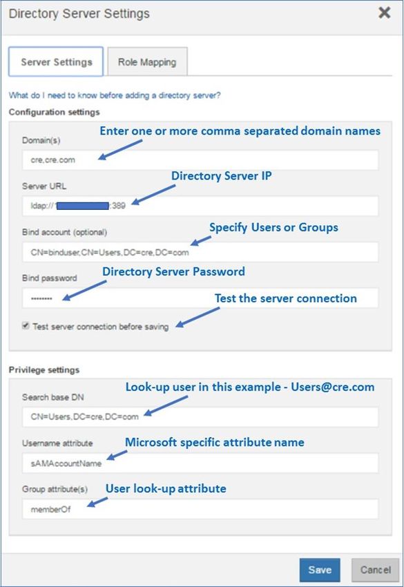
TABLE OF CONTENTS

1    E2800 Storage Systems ....................................................................................................................... 6
     1.1     E2800 Primary Use Cases ..............................................................................................................................6

     1.2     E2800 System Options ...................................................................................................................................6

2    SANtricity Management Features ....................................................................................................... 9
     2.1     Deployment .....................................................................................................................................................9

     2.2     SANtricity Unified Manager ...........................................................................................................................11

     2.3     SANtricity Unified Manager Navigation .........................................................................................................13

     2.4     SANtricity System Manager ..........................................................................................................................19

     2.5     SANtricity Storage Features..........................................................................................................................34

     2.6     SANtricity Management Integration ..............................................................................................................38

3    SANtricity Software Specifications for E2800 Hardware ................................................................ 42

4    E2800 Hardware Configurations ....................................................................................................... 44
     4.1     Controller Shelf Configurations .....................................................................................................................44

     4.2     Controller Host Interface Features ................................................................................................................48

     4.3     Hardware LED Definitions .............................................................................................................................51

     4.4     Setting the Shelf ID with the ODP Pushbutton ..............................................................................................65

5    Drive Shelves ...................................................................................................................................... 67
     5.1     Drive Shelf Configurations ............................................................................................................................68

     5.2     Greenfield Installation ...................................................................................................................................74

     5.3     Drive Shelf Hot Add ......................................................................................................................................75

6    E-Series Product Support .................................................................................................................. 78
     6.1     Controller Shelf Serial Number .....................................................................................................................78

     6.2     License Keys.................................................................................................................................................79

7    Conclusion .......................................................................................................................................... 81

Where to Find Additional Information .................................................................................................... 81

Version History ......................................................................................................................................... 81

LIST OF TABLES
Table 1) E2800 controller shelf and drive shelf models. .................................................................................................6
Table 2) Controller options with associated HIC options. ...............................................................................................8
Table 3) Management use cases. ................................................................................................................................19
Table 4) Built-in roles and associated permissions. .....................................................................................................27

 2          Introduction to NetApp E-Series E2800 Arrays:                                                                    © 2020 NetApp, Inc. All rights reserved.
            Feature Overview with SANtricity 11.60.2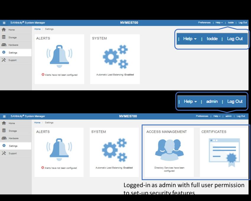
Table 5) LDAP/RBAC required fields and definitions. ..................................................................................................27
Table 6) SANtricity common host types and associated failover behavior in SANtricity 11.60.x. .................................35
Table 7) SANtricity 11.60.x features for long-term reliability. ........................................................................................35
Table 8) E2800 standard features that are included with SANtricity 11.60.x. ...............................................................37
Table 9) SANtricity 11.60.x copy services features. .....................................................................................................38
Table 10) SANtricity APIs and toolkits. .........................................................................................................................38
Table 11) Third platform plug-ins that use the SANtricity Web Services Proxy. ...........................................................39
Table 12) SANtricity software boundaries for E2800-based storage systems. .............................................................42
Table 13) E2800 technical specifications. ....................................................................................................................47
Table 14) FC host interface port speed and associated SFPs. ....................................................................................48
Table 15) iSCSI host interface port speed and associated SFPs. ................................................................................49
Table 16) E2800 controller shelf LED definitions (front panel). ....................................................................................53
Table 17) E2812, E2824, and E2860 controller shelf power and fan canister LED definitions. ....................................54
Table 18) iSCSI RJ-45 baseboard host port LED definitions. .......................................................................................56
Table 19) Ethernet management port LED definitions. .................................................................................................57
Table 20) Controller base features LED definitions. .....................................................................................................57
Table 21) 16Gb FC/10Gb iSCSI baseboard host port LED definitions. ........................................................................58
Table 22) Drive expansion port LED definitions. ..........................................................................................................59
Table 23) 2-port 10Gb iSCSI HIC LED definitions. .......................................................................................................60
Table 24) 2-port and 4-port 12Gb SAS HIC LED definitions.........................................................................................61
Table 25) 2-port and 4-port optical HIC (16Gb FC or 10Gb iSCSI) LED definitions. ....................................................63
Table 26) LED definitions for the 4-port 32Gbps FC HIC. ............................................................................................64
Table 27) LED definitions for the 4-port optical 25Gb iSCSI HIC. ................................................................................64
Table 28) Drive shelf options for E2800. ......................................................................................................................67
Table 29) IOM LED definitions. ....................................................................................................................................71
Table 30) E2812 and E2824 drive LED definitions. ......................................................................................................73
Table 31) E2860 drive LED definitions. ........................................................................................................................74

LIST OF FIGURES
Figure 1) E2800 shelf options (duplex configurations shown). .......................................................................................7
Figure 2) E2800 controller with onboard iSCSI Base-T ports and E2800 controller with optical base ports. ..................8
Figure 3) Decision tree to determine which SANtricity management components to install. ..........................................9
Figure 4) Managing a single E2800 with SANtricity System Manager. ...........................................................................9
Figure 5) Managing multiple new generation systems with SANtricity Unified Manager and SANtricity System
Manager. ......................................................................................................................................................................10
Figure 6) Managing a mixed-array environment with SANtricity Storage Manager and System Manager. ..................11
Figure 7) Final dialog box in the Web Services Proxy installation wizard. ....................................................................12
Figure 8) SANtricity Unified Manager login page. .........................................................................................................13
Figure 9) SANtricity Unified Manager landing page—discover and add arrays. ...........................................................13
Figure 10) SANtricity Unified Manager landing page. ...................................................................................................14

  3           Introduction to NetApp E-Series E2800 Arrays:                                                                     © 2020 NetApp, Inc. All rights reserved.
              Feature Overview with SANtricity 11.60.2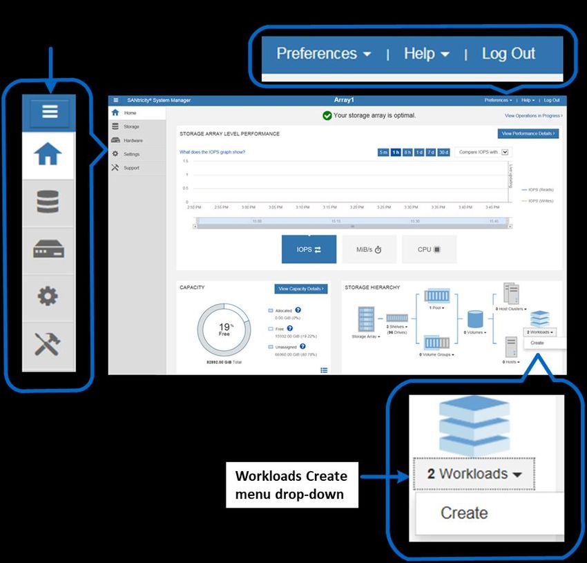
Figure 11) Creating a group to organize arrays in SANtricity Unified Manager. ...........................................................14
Figure 12) Creating a group in Unified Manager. .........................................................................................................15
Figure 13) SANtricity Unified Manager showing a newly created group. ......................................................................15
Figure 14) SANtricity Unified Manager Operations view. .............................................................................................16
Figure 15) SANtricity System Manager home page. ....................................................................................................23
Figure 16) System Manager Storage page...................................................................................................................24
Figure 17) System Manager Hardware page................................................................................................................24
Figure 18) System Manager Settings page with new security tiles...............................................................................25
Figure 19) System Manager Support page...................................................................................................................25
Figure 20) System Manager Support Center. ...............................................................................................................26
Figure 21) SANtricity System Manager directory server setup wizard. .........................................................................29
Figure 22) Role Mapping tab in the directory server settings wizard. ...........................................................................30
Figure 23) SANtricity System Manager views change based on user permission level. ..............................................31
Figure 24) Initial step required to set up web server certificates. ..................................................................................32
Figure 25) SANtricity System Manager Certificates tile expanded. ..............................................................................32
Figure 26) Opening the API documentation. ................................................................................................................39
Figure 27) Example expanding the Device-ASUP endpoint. ........................................................................................40
Figure 28) REST API documentation sample. ..............................................................................................................40
Figure 29) Sample output from the Try It Out button. ...................................................................................................41
Figure 30) Device-asup endpoint possible response codes and definitions. ................................................................41
Figure 31) Opening the CLI Command Reference. ......................................................................................................42
Figure 32) E2812 front view with bezel.........................................................................................................................44
Figure 33) E2812 front view (open). .............................................................................................................................44
Figure 34) E2812 rear view. .........................................................................................................................................44
Figure 35) E2824 front view with bezel.........................................................................................................................45
Figure 36) E2824 front view (open). .............................................................................................................................45
Figure 37) E2824 rear view. .........................................................................................................................................45
Figure 38) E2860 front view with bezel.........................................................................................................................46
Figure 39) E2860 front view (open). .............................................................................................................................46
Figure 40) E2860 rear view. .........................................................................................................................................46
Figure 41) E2800 with optical base ports HIC options. .................................................................................................50
Figure 42) E2800 with Base-T iSCSI onboard host ports: HIC options. .......................................................................51
Figure 43) ODP on the front panel of E2824 and E2812 controller shelves. ................................................................52
Figure 44) ODP on the front panel of E2860 controller shelves. ..................................................................................52
Figure 45) LEDs on the E2824 and E2812 power fan canister (rear view). ..................................................................53
Figure 46) LEDs on the E2860 power canister (rear view). ..........................................................................................54
Figure 47) Controller settings dialog box. .....................................................................................................................55
Figure 48) LEDs on the left side of E2800 controller canister with RJ-45 iSCSI host ports. .........................................56
Figure 49) LEDs on left side of E2800 controller canister with 16Gb FC/10Gb iSCSI host ports. ................................58
Figure 50) LEDs for drive expansion ports (no HIC installed).......................................................................................59

 4           Introduction to NetApp E-Series E2800 Arrays:                                                               © 2020 NetApp, Inc. All rights reserved.
             Feature Overview with SANtricity 11.60.2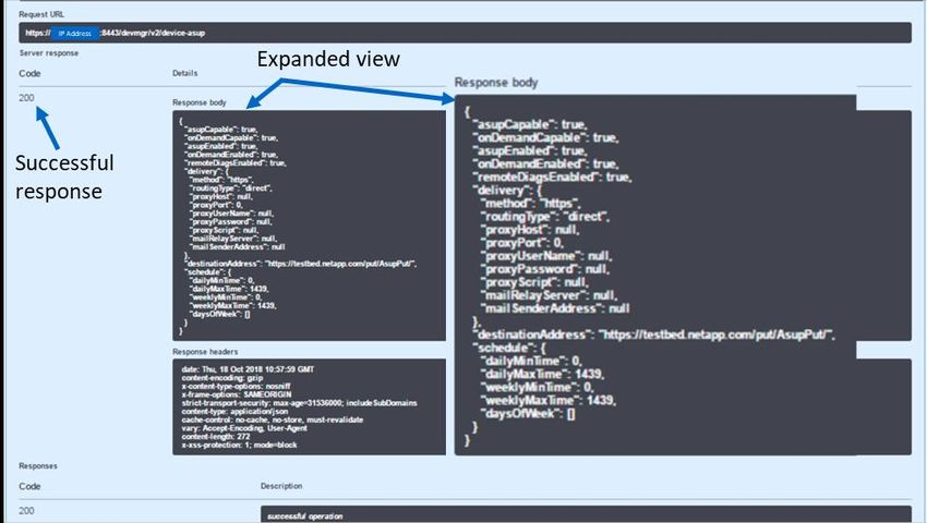
Figure 51) LEDs on the 2-port 10Gb iSCSI RJ-45 HIC. ...............................................................................................60
Figure 52) LEDs for the 4-port 12Gb SAS HIC. ............................................................................................................61
Figure 53) LEDs for the 2-port 12Gb SAS HIC. ............................................................................................................61
Figure 54) LEDs for the 4-port optical HIC (16Gb FC or 10Gb iSCSI). ........................................................................62
Figure 55) LEDs for the 2-port optical HIC (16Gb FC or 10Gb iSCSI). ........................................................................63
Figure 56) LEDs for the 4-port 32Gb FC HIC. ..............................................................................................................63
Figure 57) LEDs for the 4-port 25Gb iSCSI HIC. ..........................................................................................................64
Figure 58) ODP on the E2812 or DE212C (front bezel or end caps removed). ............................................................65
Figure 59) ODP on the E2824 or DE224C (front bezel or end caps removed). ............................................................66
Figure 60) ODP on the E2860 or DE460C (front bezel removed). ...............................................................................66
Figure 61) DE212C front view with end caps. ..............................................................................................................68
Figure 62) DE212C front view without end caps. .........................................................................................................68
Figure 63) DE212C rear view. ......................................................................................................................................68
Figure 64) DE224C front view with end caps. ..............................................................................................................69
Figure 65) DE224C front view without end caps. .........................................................................................................69
Figure 66) DE224C rear view. ......................................................................................................................................69
Figure 67) DE460C front view with bezel. ....................................................................................................................70
Figure 68) DE460C front view without bezel. ...............................................................................................................70
Figure 69) DE460C rear view. ......................................................................................................................................70
Figure 70) LEDs for IOM. .............................................................................................................................................71
Figure 71) E2812 drive carrier LEDs. ...........................................................................................................................72
Figure 72) E2824 drive carrier LEDs. ...........................................................................................................................72
Figure 73) E2860 shelf and drawer attention LEDs. .....................................................................................................73
Figure 74) E2860 drive attention LED. .........................................................................................................................73
Figure 75) E2800 single-stack system configuration. ...................................................................................................74
Figure 76) E2800 storage system dual-stack configuration with SAS 3 and SAS 2 shelves. .......................................75
Figure 77) Drive shelf hot-add A-side cabling...............................................................................................................76
Figure 78) Drive shelf hot-add B-side cabling...............................................................................................................77
Figure 79) Controller shelf SN. .....................................................................................................................................78
Figure 80) SANtricity System Manager Support Center tile showing chassis serial number. .......................................79
Figure 81) Change feature pack from Settings>System view. ......................................................................................80
Figure 82) Change feature pack. ..................................................................................................................................80

 5           Introduction to NetApp E-Series E2800 Arrays:                                                               © 2020 NetApp, Inc. All rights reserved.
             Feature Overview with SANtricity 11.60.2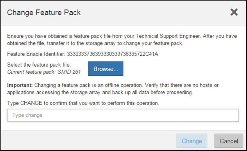
1 E2800 Storage Systems
NetApp E-Series E2800 storage systems address wide-ranging data storage requirements with balanced
performance that is equally adept at handling large sequential I/O for video, analytical, and backup
applications. It is also suited for handling small random I/O requirements for small and medium-sized
enterprise mixed workloads. The E2800 brings together the following advantages:
•       Support for hybrid drive configurations
•       Host interface flexibility (SAS, FC, and iSCSI)
•       High reliability (up to 99.9999%)
•       Intuitive management. Simple administration for IT generalists, detailed drill-down for storage
        specialists
•       The new SANtricity Unified Manager central management interface provides timesaving features not
        available with the legacy Storage Manager Enterprise Management Window (EMW)
Together, these features create an entry-level storage system with the flexibility and performance
capabilities to support enterprise workloads without sacrificing simplicity and efficiency. In addition, the
E2800 storage system’s fully redundant I/O paths, advanced protection features, and extensive
diagnostic capabilities deliver a high level of availability, data integrity, and security.

1.1       E2800 Primary Use Cases
The flexible host interface options and wide range of drive choices make E-Series E2800 storage
systems an optimal storage platform for enterprises that need powerful storage systems with easy growth
strategies at the lowest possible initial investment. E2800 storage systems can scale up for dedicated
workloads such as:
•       Business-critical backup environments for enterprises of any size
•       Video applications and video surveillance environments
•       Common IT applications such as Microsoft Exchange and SQL Server for small and medium
        enterprises
•       Efficient block storage for integrated appliances

1.2       E2800 System Options
As shown in Table 1, the E2800 is available in three shelf options, which support both HDDs and solid-
state drives (SSDs), to meet a wide range of performance and application requirements.

Table 1) E2800 controller shelf and drive shelf models.

 Controller Shelf Model             Drive Shelf Model       Number of Drives per      Type of Drives
                                                            Shelf
 E2812                              DE212C                  12                        3.5" NL-SAS drives
                                                                                      2.5" SAS SSDs

 E2824                              DE224C                  24                        2.5" SAS drives (HDDs
                                                                                      and SSDs)

 E2860                              DE460C                  60                        3.5" NL-SAS drives
                                                                                      2.5" SAS drives (HDDs
                                                                                      and SSDs)

 Note:       The E2812 supports a maximum of four shelves, which includes one controller drive shelf, and
             up to three expansion drive shelves. E2824 uses the same shelf count, that is, 96 total drive
             slots (4 x 24-drive shelves). The E2860 supports up to two expansion drive shelves for a total of

    6       Introduction to NetApp E-Series E2800 Arrays:                          © 2020 NetApp, Inc. All rights reserved.
            Feature Overview with SANtricity 11.60.2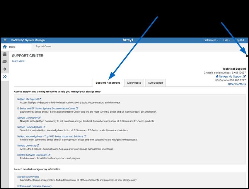
Controller Shelf Model         Drive Shelf Model       Number of Drives per      Type of Drives
                                                        Shelf
         180 drive slots. All shelf models can be mixed in the same storage array, but 180 total drive
         slots are the maximum drive slot count supported with the E2800 array family.

The E2812 and E2824 shelf options support one (simplex configuration) or two (dual configuration)
controller canisters, while the E2860 supports only two controller canisters. All shelves support dual
power supplies and dual fan units for redundancy. However, the 12- and 24-drive shelves have dual
integrated power and fan canisters, whereas the 60-drive shelf (DE460C) has separate dual power
supplies and fan units. The shelves are sized to hold 12 drives, 24 drives, or 60 drives, as shown in
Figure 1.
Note:   In a duplex configuration, both controllers must be identically configured.

Figure 1) E2800 shelf options (duplex configurations shown).

Note:   The DE460C 4-rack unit (RU) 60-drive shelf requires dual ~220VAC power sources to power
        each shelf.
Each E2800 controller provides two Ethernet management ports for out-of-band management and has
two 12Gbps (x4 lanes) wide-port SAS drive expansion ports for redundant drive expansion paths. The
E2800 controllers also include two built-in host ports, either two optical 16Gb FC/10Gb iSCSI or two 10Gb

 7      Introduction to NetApp E-Series E2800 Arrays:                          © 2020 NetApp, Inc. All rights reserved.
        Feature Overview with SANtricity 11.60.2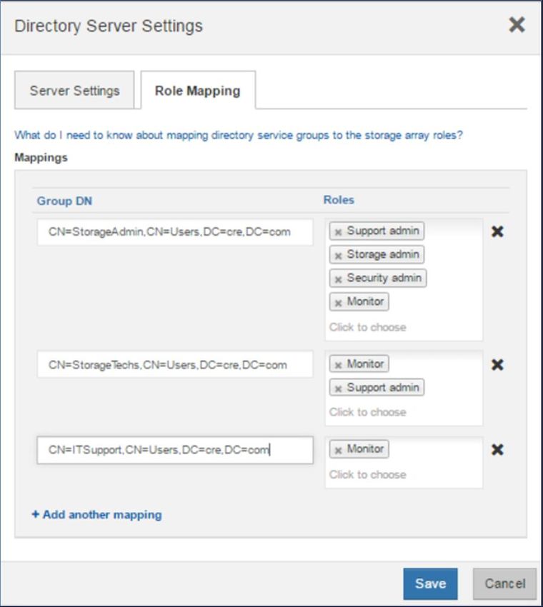
iSCSI Base-T ports. One of the host interface cards (HICs), listed in Table 2, can be installed in each
controller.

Table 2) Controller options with associated HIC options.

 Controller Type             2-Port / 4-          2-Port / 4-Port   4-Port    4-Port 25Gb          2-Port 10Gb
                             Port 12Gb            16Gb FC / 10Gb    32Gb FC   iSCSI                iSCSI (Base-T)
                             SAS HIC              iSCSI HIC
 E2800 w/ Optical            Yes                  Yes               Yes       Yes                  Yes
 Baseboard Ports

 E2800 w/ Base-T             Yes                  No                No        No                   Yes
 Baseboard Ports

Note:   A software feature pack can be applied in the field to change the host port protocol of the optical
        baseboard ports and the optical HIC ports from FC to iSCSI or from iSCSI to FC. Mixed protocol
        configurations are supported when the baseboard host ports are set for one protocol and the
        expansion HIC ports are set for a different protocol.
For optical connections, appropriate SFPs must be ordered for a specific implementation. All E2800
optical connections use OM4 fiber cable. Consult the Hardware Universe for a full listing of available host
interface equipment. Figure 2 provides a close-up view of the E2800 onboard host interface options.

Figure 2) E2800 controller with onboard iSCSI Base-T ports and E2800 controller with optical base ports.

Note:   For 16Gb/8Gb/4Gb FC or 10Gb iSCSI, use the unified SFP (X-48895-00-R6-C), but for 1Gb
        iSCSI, you must use the 1Gb iSCSI SFP (X-48896-00-C).
For detailed instructions about changing the host protocol, go to the Upgrading > Hardware Upgrade
section at https://mysupport.netapp.com/eseries.

 8      Introduction to NetApp E-Series E2800 Arrays:                              © 2020 NetApp, Inc. All rights reserved.
        Feature Overview with SANtricity 11.60.2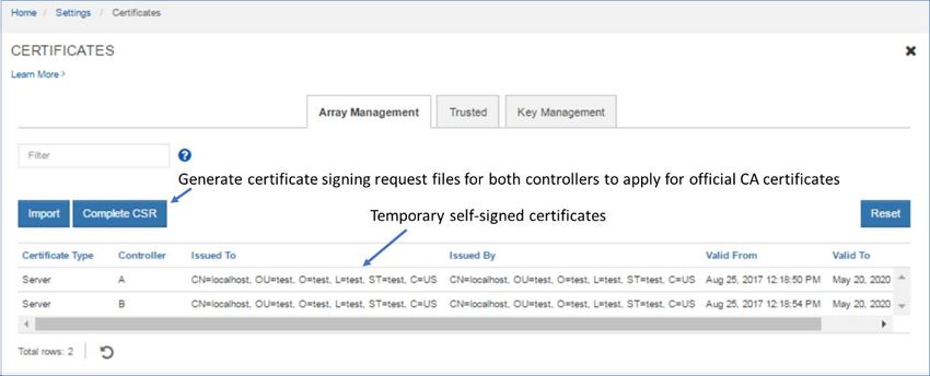
2 SANtricity Management Features
NetApp E-Series and EF-Series arrays have a rock-solid reputation for reliability, availability, simplicity,
and security. The NetApp SANtricity 11.60.2 release builds on that legacy by adding a secure CLI to
SANtricity System Manager and improving the configuration of mirroring in SANtricity Unified Manager.
The new generation E-Series and EF-Series arrays running the latest SANtricity OS are common criteria
certified (NDcPP v2 certification) and are listed on the Canadian Communications Security Establishment
(CSE) site.

2.1     Deployment
Deciding which components to install on an E2800-based storage array depend on how you answer the
questions in Figure 3.

Figure 3) Decision tree to determine which SANtricity management components to install.

Note:    If you are not using synchronous or asynchronous mirroring features and only have new
         generation E5700 or E2800 storage arrays, an alternative to installing the Unified Manager to
         manage multiple arrays is to bookmark each array in a web browser.

Single E2800 Storage Array
If you only have a single new array and are not using synchronous or asynchronous mirroring features,
then all configuration can be handled from SANtricity System Manager. Figure 4 illustrates this
configuration.

Figure 4) Managing a single E2800 with SANtricity System Manager.

 9       Introduction to NetApp E-Series E2800 Arrays:                          © 2020 NetApp, Inc. All rights reserved.
         Feature Overview with SANtricity 11.60.2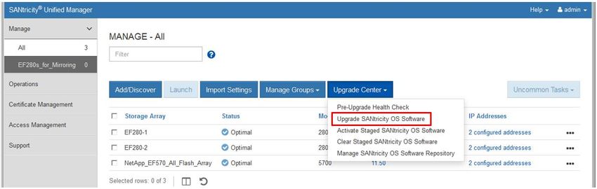
Multiple New Generation Storage Arrays
If you have one or more new generation storage arrays, you can install Unified Manager to manage your
overall environment while still handling all storage array-based configuration through SANtricity System
Manager. To manage multiple arrays, you can launch SANtricity System Manager from Unified Manager,
as shown in Figure 5.

Figure 5) Managing multiple new generation systems with SANtricity Unified Manager and SANtricity System
Manager.

Mix of New Generation and Legacy Storage Arrays
For mixed-generation environments that have legacy E2700 or E5600 arrays and new generation E2800
or E5700 arrays, do the following (Figure 6):
•        Use the SANtricity Storage Manager Enterprise Management Window (EMW) to launch SANtricity
         System Manager for array-based tasks on the E2800 storage arrays.
•        Use the AMW for array-based tasks on legacy E-Series storage arrays.

    10       Introduction to NetApp E-Series E2800 Arrays:                      © 2020 NetApp, Inc. All rights reserved.
             Feature Overview with SANtricity 11.60.2
Figure 6) Managing a mixed-array environment with SANtricity Storage Manager and System Manager.
For a detailed description of installing and configuring the components you choose, see the appropriate
Express Guides for deployment instructions.
2.2 SANtricity Unified Manager
SANtricity Unified Manager is a web-based central management interface that replaces the legacy
SANtricity Storage Manager Enterprise Management Window (EMW) for managing new generation
E2800/EF280 and E5700/EF570 E-Series arrays. The Unified Manager GUI is bundled with the
SANtricity Web Services Proxy starting with version 3.0 and installs on a management server with IP
access to the managed arrays. Unified Manager can manage up to 500 arrays.
SANtricity Unified Manager has added the following time-saving features:
• Upgrade multiple arrays with the same type of controller at one time.
• Supports Lightweight Directory Access Protocol (LDAP) and role-based access control (RBAC) just
like SANtricity System Manager. Unified Manager includes a simplified certificate management
workflow to manage the Unified Manager or Web Services Proxy server certificates (truststore and
keystore certificates).
• Supports organizing arrays by groups that you can create, name, and arrange.
• Supports importing common settings from one array to another, saving time from duplicating setup
steps for each array.
• Fully supports managing mirroring.
11 Introduction to NetApp E-Series E2800 Arrays: © 2020 NetApp, Inc. All rights reserved.
Feature Overview with SANtricity 11.60.2• Supports synchronous and asynchronous mirroring for E2800/EF280 and E5700/EF570 arrays
through the secure SSL interface. The EMW is only required if the initiator or target array is a legacy
E2700, E5600/EF560, or earlier array model.
E-Series SANtricity Unified Manager or the E-Series SANtricity Web Services Proxy is available on the
NetApp Support software download page. Either listing takes you to the combined Web Services Proxy
with SANtricity Unified Manager download page.
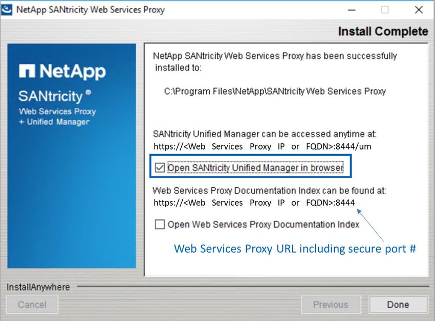
After the installation wizard completes, you can open Unified Manager, or you can directly access the
SANtricity Web Services Proxy as shown in Figure 7.
Figure 7) Final dialog box in the Web Services Proxy installation wizard.
If you want to open the Unified Manager UI after the Web Services Proxy installation, open a browser and
navigate to the server IP address and secure port number that was reserved during the Web Services
Proxy software installation. For example, enter the URL in the form https://:/, and then select the link for Unified Manager. You could go directly to the Unified Manager login page
(Figure 8) by adding /um to the URL. For example, https://:/um.
12 Introduction to NetApp E-Series E2800 Arrays: © 2020 NetApp, Inc. All rights reserved.
Feature Overview with SANtricity 11.60.2Figure 8) SANtricity Unified Manager login page.
2.3 SANtricity Unified Manager Navigation
The login page for SANtricity Unified Manager has a similar appearance to SANtricity System Manager
and requires administrators to set the array admin password as part of the initial login. SANtricity Unified
Manager has a factory default admin account: admin.
Discovering and Adding Storage Arrays
Like the SANtricity EMW, SANtricity Unified Manager must discover arrays to manage, and, like the
EMW, you can discover a single array or scan a range of IP addresses to discover multiple arrays
simultaneously. Select the tab or link shown in Figure 9 to open the Add/Discover wizard. After
discovering arrays, you then choose to manage them with Unified Manager.
Figure 9) SANtricity Unified Manager landing page—discover and add arrays.
13 Introduction to NetApp E-Series E2800 Arrays: © 2020 NetApp, Inc. All rights reserved.
Feature Overview with SANtricity 11.60.2After the arrays are discovered and added, they are displayed on the landing page of Unified Manager
(Figure 10).
Figure 10) SANtricity Unified Manager landing page.
Organizing Arrays by Group
After you add arrays to Unified Manager, you can group them to organize your array management
environment. Figure 11 shows EF280 arrays added to a group. This capability is available for all new
generation E-Series and EF-Series arrays.
Figure 11) Creating a group to organize arrays in SANtricity Unified Manager.
The built-in wizard makes adding arrays to groups quick and easy, as shown in Figure 12.
14 Introduction to NetApp E-Series E2800 Arrays: © 2020 NetApp, Inc. All rights reserved.
Feature Overview with SANtricity 11.60.2Figure 12) Creating a group in Unified Manager.
SANtricity Unified Manager allows you to see just the subset of arrays in the new group, as shown in
Figure 13.
Figure 13) SANtricity Unified Manager showing a newly created group.
Importing Settings and Viewing Operations
Other features in SANtricity Unified Manager require the ability to view operations that take some time to
complete. One example is importing settings from one storage array to another. This feature is especially
helpful and time saving when you install a new array in an environment that already contains E-Series or
EF-Series arrays running SANtricity 11.50 or later. For example, if you want the same alerting and
NetApp AutoSupport® settings on all systems, use the Import Settings wizard to select the setting
category, the array to copy from, and the array to import to and click Finish. The operation to copy the
settings is displayed in the Operations view, as shown in Figure 14.
15 Introduction to NetApp E-Series E2800 Arrays: © 2020 NetApp, Inc. All rights reserved.
Feature Overview with SANtricity 11.60.2Note: Be careful when importing settings from another storage array, especially if you have different
alerting requirements and unique storage configurations. The storage configuration option is
successful only when the source and destination arrays have identical hardware configurations.
The import feature does not show details about the pending import and does not prompt for
confirmation. When you click Finish, you cannot stop the copy/import process.
Figure 14) SANtricity Unified Manager Operations view.
Updating SANtricity OS Through Unified Manager
To upgrade the array’s firmware, complete the following steps:
1. Import the SANtricity OS software into the Unified Manager’s SANtricity OS Software Repository
using the Manage SANtricity OS Software Repository dialog under Upgrade Center on the landing
page.
2. On the Unified Manager landing page, click Upgrade Center and then click Upgrade SANtricity OS
Software.
16 Introduction to NetApp E-Series E2800 Arrays: © 2020 NetApp, Inc. All rights reserved.
Feature Overview with SANtricity 11.60.23. On the Upgrade SANtricity OS Software page, select the following items:
− The desired SANtricity OS and/or NVSRAM files
− The arrays to be upgraded that are appropriate to the selected SANtricity OS files
− Whether to transfer and activate the OS files immediately or later
4. Click Start to continue.
5. On the Confirm Transfer and Activation page, enter Upgrade and then click Upgrade to begin the
SANtricity OS files transfer.
17 Introduction to NetApp E-Series E2800 Arrays: © 2020 NetApp, Inc. All rights reserved.
Feature Overview with SANtricity 11.60.2After transfer starts, the Upgrade SANtricity OS Software window is displayed. The status of the
selected arrays is updated throughout the upgrade process. The first status is Health Check in
Progress, followed by File Transfer in Progress, and finally Reboot in Progress.
After the files have been transferred and the controllers have completed rebooting, the status
changes to OS Software Upgrade Successful.
Back on the Unified Manager landing page, the SANtricity OS Software version reflects the newly
installed SANtricity OS version.
18 Introduction to NetApp E-Series E2800 Arrays: © 2020 NetApp, Inc. All rights reserved.
Feature Overview with SANtricity 11.60.2SANtricity Unified Manager Security
SANtricity Unified Manager supports the same secure management features as SANtricity System
Manager, including LDAP, RBAC, and SSL certificates. For complete details and workflow examples, see
TR-4712: NetApp SANtricity Management Security Feature Details and Configuration Guide.
Remote Mirroring with SANtricity Unified Manager
With Unified Manager, you can set up remote mirroring between two E2800/EF280 and/or E5700/EF570
arrays. Starting with SANtricity 11.62, Unified Manager is used to create the mirror relationship. See
SANtricity Synchronous and Asynchronous Mirroring (11.62 and above) in the E-Series and SANtricity 11
Documentation Center or the Online Help in SANtricity Unified Manager for a complete description.
SANtricity Unified Manager must be version 4.2 or later and SANtricity System Manager must be OS
version 11.62 or later.
Prior to SANtricity 11.62, for a description of mirroring between two new generation E-Series arrays or
between a new generation E-Series array and a legacy E-Series array, see SANtricity Synchronous and
Asynchronous Mirroring (11.61 and below).
2.4 SANtricity System Manager
Overview
SANtricity System Manager provides embedded management software, web services, event monitoring,
secure CLI, and AutoSupport for E2800 arrays. Previous arrays that use the E2700 and E5600 controllers
do not have this embedded functionality or the security features introduced in SANtricity System Manager
11.40 and later versions. There are various management options if you have a mixed environment with a
new E2800 and legacy E-Series storage arrays. Table 3 provides an overview of management use cases.
Table 3) Management use cases.
Task Mixed environment E5700/EF570/E2800/EF280 only
Manage and Discover
Discover an array in your EMW • SANtricity Unified Manager
management domain
Add an array to or remove an • EMW • SANtricity Unified Manager
array from your management • SANtricity storage management
domain CLI (SMcli)
19 Introduction to NetApp E-Series E2800 Arrays: © 2020 NetApp, Inc. All rights reserved.
Feature Overview with SANtricity 11.60.2Task Mixed environment E5700/EF570/E2800/EF280 only
Launch SANtricity System N/A • SANtricity Unified Manager
Manager • Directly from browser
Launch the AMW EMW N/A
AutoSupport and Legacy Support Bundle Collection
Enable or disable AutoSupport, • EMW • System Manager
AutoSupport OnDemand, and • SMcli • SANtricity Unified Manager
AutoSupport remote diagnostics
• SANtricity Web Services Proxy
features
(REST)
• System Manager Secure CLI
Show AutoSupport logs for all • EMW • System Manager
arrays or a select storage array • SMcli • REST
• Secure CLI
Enable or disable legacy support • EMW N/A
bundle collection for a select • SMcli
storage array
Specify the support bundle • EMW N/A
collection schedule • SMcli
Configuration and Status
Display information (other than • AMW • System Manager
alert settings) about configured • SANtricity Web Services Proxy • REST
arrays (REST) • Secure CLI
• SMcli
Show the IP address of each array • AMW • SANtricity Unified Manager
• REST • System Manager
• SMcli • REST
• Secure CLI
Show the WWN of each array • AMW • System Manager
• REST • REST
• SMcli • Secure CLI
Show the status of each array • EMW/AMW • SANtricity Unified Manager
• REST • System Manager
• SMcli • REST
• Secure CLI
Set up remote volume mirroring • EMW/AMW • SANtricity Unified Manager and
groups and pairs • REST System Manager
• SMcli
Show array-level configuration, • AMW • System Manager
provisioning, and tuning • REST • REST
• SMcli • Secure CLI
20 Introduction to NetApp E-Series E2800 Arrays: © 2020 NetApp, Inc. All rights reserved.
Feature Overview with SANtricity 11.60.2Task Mixed environment E5700/EF570/E2800/EF280 only
Alert and SNMP Configuration
Show or configure global alert • EMW • N/A
settings • REST • REST
• SMcli
Configure email server or SNMP • EMW • System Manager
settings for an array • REST • REST
• SMcli
Send a test email based on global • EMW • N/A
alert settings • REST • REST
• SMcli
Certificate handling: view SSL N/A • System Manager
information, get a certificate • REST
signing request (CSR), import a
new certificate
More convenient syslog N/A • System Manager
configuration • REST
Save up to 30 days of historical N/A • System Manager
statistical I/O data • REST
Apply application tags to volumes N/A • System Manager
• REST
E2800 storage systems are shipped preloaded with SANtricity 11.60.x, which includes SANtricity System
Manager 11.60. To discover E2800 storage systems running SANtricity 11.60.x from a central view,
download the latest version of the Web Services Proxy, which includes the latest version of SANtricity
Unified Manager. To manage a mixed legacy and new generation environment, download the latest
version of SANtricity Storage Manager 11.6x from the NetApp Support site to a management server that
has IP access to the storage systems.
Note: The x in the SANtricity Storage Manager version number must be greater than or equal to the x in
the SANtricity 11.60.x version number.
Previous versions of SANtricity Storage Manager (the EMW) cannot discover E2800 arrays running
SANtricity 11.60.x. However, SANtricity Storage Manager 11.6x can discover new E2800 arrays and all
previous E-Series array software versions from the last five years.
Following are reasons to download and install at least some portions of the SANtricity Storage Manager
software package:
• You have multiple legacy and new generation E-Series or EF-Series arrays and want the enterprise
view from the EMW.
• You plan to use synchronous or asynchronous remote mirroring from older-generation arrays and
new-generation arrays.
• You need to use SMcli in legacy mode.
• You need the Host Utilities package (SMutils) for legacy arrays. The host package is loaded on I/O-
generating hosts.
• You need to install the Microsoft Windows device-specific module (DSM) on a Windows host for
multipath failover (delivered as part of the Windows host package).
21 Introduction to NetApp E-Series E2800 Arrays: © 2020 NetApp, Inc. All rights reserved.
Feature Overview with SANtricity 11.60.2Following are reasons to download and install the latest version of the SANtricity Web Services Proxy and
Unified Manager:
• You have multiple new generation E-Series or EF-Series arrays and want the enterprise view from
SANtricity Unified Manager.
• You plan to use synchronous or asynchronous remote mirroring with only new generation arrays.
• You want to use the new management features to set up and organize arrays in a more user-friendly
UI.
• You want a more secure enterprise view that supports the same user and session security as
SANtricity System Manager.
If you do not want to use the SANtricity EMW or SANtricity Unified Manager to discover and manage your
E-Series arrays, you do not need to download and install the legacy SANtricity Storage Manager or Web
Services Proxy software. When customers implement E-Series with Windows and Linux operating
systems, they can use the settings in the Host Utilities to properly configure each host, according to the
latest Interoperability Matrix Tool (IMT) guidance. See the appropriate OS Express Guide for host setup
requirements, instructions, and references. The guides are available from the NetApp Support site at
https://mysupport.netapp.com/eseries.
Note: Creating an account on the NetApp Support site can take 24 hours or more for first-time
customers. New customers should register for Support site access well before the initial product
installation date.
System Manager Navigation
• After you log in to SANtricity System Manager, the home page is displayed, as shown in Highlighted
on the bottom-right corner is a Storage Hierarchy view of your array that includes the ability to
provision the storage.
Figure 15.
• The icons on the left of the home page are used to navigate through the System Manager pages and
are available on all pages. The text can be toggled on and off.
• The items on the top right of the page (Preferences, Help, Log Out) are also available from any
location in System Manager.
• Highlighted on the bottom-right corner is a Storage Hierarchy view of your array that includes the
ability to provision the storage.
22 Introduction to NetApp E-Series E2800 Arrays: © 2020 NetApp, Inc. All rights reserved.
Feature Overview with SANtricity 11.60.2Figure 15) SANtricity System Manager home page.
Figure 16, Figure 17, Figure 18, and Figure 19 show the other four main pages that are used in SANtricity
System Manager and that are accessible from anywhere in the application.
23 Introduction to NetApp E-Series E2800 Arrays: © 2020 NetApp, Inc. All rights reserved.
Feature Overview with SANtricity 11.60.2Figure 16) System Manager Storage page.
Figure 17) System Manager Hardware page.
24 Introduction to NetApp E-Series E2800 Arrays: © 2020 NetApp, Inc. All rights reserved.
Feature Overview with SANtricity 11.60.2Figure 18) System Manager Settings page with new security tiles.
Note: Figure 18 shows the view for an administrator or security administrator. Others with a lower
access permission level see only the Alerts and System tiles.
Figure 19) System Manager Support page.
Figure 20 displays the Support Center, which you can reach by selecting the Support Center tile on the
Support page. From the Support Center, use navigation tabs to reach support topics.
25 Introduction to NetApp E-Series E2800 Arrays: © 2020 NetApp, Inc. All rights reserved.
Feature Overview with SANtricity 11.60.2Figure 20) System Manager Support Center.
SANtricity System Manager Security
SANtricity System Manager supports multiple levels of management interface security including:
• Support for directory services using LDAP.
• Support for RBAC: five standard roles with varying permission levels.
• Support for certification authority (CA) and SSL certificates.
• Implementation of a secure CLI. The CLI is secure when the certificates are installed. Syntax and
invocation are the same as in the legacy CLI, but additional security parameters are supplied.
• Security enhancements that extend to the onboard web services API, where user account passwords
are now required.
Note: If you want to run in the previous security mode with a single administrative password and
still use symbols to communicate through the legacy API, the new security features can be
disabled by the admin or security users.
LDAP and RBAC
LDAP is a commonly used communication protocol that enables directory servers such as Microsoft
Active Directory to provide centralized identity control over user and group definitions.
RBAC is software on the E-Series array that defines standard user levels, each with a well-defined set of
access permissions. By authenticating a user as a member of a group and setting group permissions on
26 Introduction to NetApp E-Series E2800 Arrays: © 2020 NetApp, Inc. All rights reserved.
Feature Overview with SANtricity 11.60.2the array side, SANtricity 11.40 and later versions provide the granularity of access that customers
require.
Table 4 defines the permission level with each role.
Table 4) Built-in roles and associated permissions.
Role Name (login as) Access Permissions
Root Admin (admin) This role allows you to change the passwords of any local users and execute any
command supported by the array. The admin password is set at initial login or any
time after.
Security Admin This role allows you to modify security configuration settings on the array. It allows
(security) you to view audit logs; configure secure syslog server, LDAP, or LDAPS server
connections; and manage certificates. This role provides read access but does not
provide write access to storage array properties such as pool or volume creation or
deletion. This role also has privileges to enable or disable SYMbol access to the
array.
Storage Admin This role allows full read and write access to the storage array properties and
(storage) maintenance/diagnostics functions. However, it does not include access to perform
any security configuration functions.
Support Admin This role provides access to all hardware resources on the array, failure data, the
(support) MEL/Audit log, and CFW upgrades. You can view the storage configuration but
cannot change it.
Monitor (monitor) This role provides read-only access to all storage array properties. However, you
are not able to view the security configuration.
Setting Up the Directory Server and Roles
Directory servers, like most data center devices, are complex and designed to fulfill many use cases.
However, the E-Series LDAP/RBAC implementation focuses on authentication and two main elements:
users and groups. As with most applications, you must understand a few acronyms and follow a few
conventions to set up communication between the E-Series array and the directory server. The most
critical acronyms to understand are the following:
• CN. Stands for commonName, used to identify group names as defined by the directory server tree
structure.
• DC. Stands for domainComponent, the network in which user and groups exist (for example,
netapp.com).
• DN. Stands for distinguishedName, the fully qualified domain name made up of one or more
comma-separate common names, followed by one or more comma-separated DCs (for example,
CN=functional_group_name,CN=Users,DC=netapp,DC=com).
E-Series systems follow a standard web server implementation on the controllers, and information about
the general directory services setup is available on the web. As a result, setting up the service on E-
Series systems only requires some fields, which are listed in Table 5.
Table 5) LDAP/RBAC required fields and definitions.
Field Name Definitions
Domain (for example, Network domains defined in the directory server of which users accessing the
netapp.com) storage array are members.
27 Introduction to NetApp E-Series E2800 Arrays: © 2020 NetApp, Inc. All rights reserved.
Feature Overview with SANtricity 11.60.2Field Name Definitions
Server URL Can be a fully qualified domain name or IP and port number in the format
ldap:// (port 389 or port 636 for LDAPS).
Bind account Format is CN=binduser,CN=Users,DC=,DC=com.
Bind account password Password for bind account user.
Search base DN Format is CN=Users,DC=,DC=com.
Username attribute The LDAP attribute that defines the username. Example: sAMAccountName is
a standard entry for legacy Windows-based browsers, including Windows 95,
Windows 98, and Windows XP. Linux can have other designations.
Group attributes The LDAP attribute that defines the groups to which a user belongs. Example:
memberOf is a standard attribute.
Figure 21 shows a sample Active Directory server integration with SANtricity System Manager. The
entries are all examples except for username attributes and group attributes in the privileges section.
Those items are standard entries for Windows and are not likely to change for most implementations.
28 Introduction to NetApp E-Series E2800 Arrays: © 2020 NetApp, Inc. All rights reserved.
Feature Overview with SANtricity 11.60.2Figure 21) SANtricity System Manager directory server setup wizard.
The array roles for the specified user groups are set in the Role Mapping tab. In Figure 22, users who are
members of the StorageAdmin, StorageTechs, and ITSupport groups are authenticated as branches of
the Users group @cre.com. When users in one of those groups log in to the array, they are allowed
access to certain views and functions in the management interface according to the permissions granted.
29 Introduction to NetApp E-Series E2800 Arrays: © 2020 NetApp, Inc. All rights reserved.
Feature Overview with SANtricity 11.60.2You can also read