INSTALLATION AND USER GUIDE ADAPTEC SMARTRAID 3100 SERIES AND SMARTHBA 2100 SERIES HOST BUS ADAPTERS - RELEASED FEBRUARY 2020
←
→
Page content transcription
If your browser does not render page correctly, please read the page content below
.
              Installation and User Guide
   Adaptec® SmartRAID 3100 Series and
SmartHBA 2100 Series Host Bus Adapters
                                   Released
                               February 2020
Revision History
Revision Revision    Details of Change
         Date
8       February     Updated for SR2.5.2 release. Add specs, illustrations, features, installation procedures, and regulatory compliance for SmartRAID
        2020         3101E-4i and SmartRAID 3102E-8i adapters. Add new UEFI/HII options: Modify Cache Settings, Out of Band Messaging Settings
                     (PBSI/MCTP configuration).
7       August       Updated for SR2.4.8 release: update Solaris SmartPQI driver installation instructions; add "SmartRAID/SmartHBA Physical and
        2019         Logial Device Support" appendix.
6       January      Updated for SR2.4 release. Add support for new SKU: SmartHBA 2100-16i. Add support for UEFI Configure Controller Port
        2019         Mode; revise UEFI Encryption Manager Full Setup task flow; add caution and describe effects of UEFI Reset Controller to Factory
                     Defaults.
5       April 2018   Clarify cache protection options and revise board illustrations for SmartRAID 3151-4i and SmartRAID 3154-8i controllers.
                     Update max supported drives with expanders.
4       April 2018   Updated for SR2.3 release. Add support for new skus: SmartRAID 3162-8i, SmartRAID 3162-8i /e, SmartRAID 3154-8i8e,
                     SmartRAID 3154-8i16e, SmartHBA 2100-8i8e. Add support for UEFI Encryption Manager, Create maxCache Arrray, and Reset
                     controller to factory defaults.
3       December     Updated supported operating systems
        2017
2       November     1. Updated supported operating systems.
        2017
                     2. Revised controller airflow requirements.

1       October      First Production Release.
        2017

                               Microsemi Proprietary and Confidential Installation and User Guide Revision 8                                         ii
Microsemi Adaptec® Product Support
Microsemi Adaptec® Product Support
If you have questions about installing or using your Microsemi Adaptec® product, check this document
first—you will find answers to most of your questions. If you need further assistance, use the support
options listed below. To expedite your service, have your computer in front of you.
Note: Please visit our Support site at start.microsemi.com for the most up to date contact
information.
Self Help and Support in English
• Search the Microsemi Support Knowledgebase (ASK) at ask.microsemi.com for articles, troubleshooting
tips, and frequently asked questions for your product.
• For support through email, submit your question at ask.microsemi.com.
• To contact Technical Support, visit our product support site at start.microsemi.com.
Technische Informationen und Support in Deutsch
• Suchen Sie in der Adaptec Support Knowledgebase (ASK) unter ask-de.microsemi.com nach Artikeln,
Tipps zur Fehlerbehebung und häufig gestellten Fragen zu Ihrem Produkt.
• Support per Email erhalten Sie unter ask-de.microsemi.com.
• Um den Technischen Support zu kontaktieren, besuchen Sie uns bitte unter start.microsemi.com und
klicken Sie auf „Support kontaktieren“, für Auswahlmöglichkeiten.
Техническая поддержка и информация на русском языке
• База знаний Microsemi (ASK) на сайте ask-ru.microsemi.com ask-ru.adaptec.com – статьи, советы
по устранению неисправностей и часто задаваемые вопросы о Вашем продукте.
• Для поддержки по электронной почте отправьте Ваш запрос на сайте ask-ru.microsemi.com
• Для обращения в службу Технической Поддержки, пожалуйста, посетите наш web сайт
start.microsemi.com и используйте ссылку "Contact Support".
日本語での技術情報とサポート
• ask.microsemi.co.jp のMicrosemi Support Knowledgebase (ASK)で、お使いの製品の情報 トラブル
シューティングのヒント、よくある質問を検索してください。
• Eメールでのサポートには ask.microsemi.co.jp から質問を送ってください。
• テクニカルサポートへコンタクトするには、弊社ウェブサイトstart.microsemi.comをご覧に
なり、"Contact Support“をクリックして下さい。
Microsemi Proprietary and Confidential Installation and User Guide Revision 8 iiiLimited 3-Year Hardware Warranty
Limited 3-Year Hardware Warranty
1. Microsemi Corporation (“Microsemi”) warrants to the purchaser of this product that it will be free from
defects in material and workmanship for a period of three (3) years from the date of purchase. If the
product should become defective within the warranty period, Microsemi, at its option, will repair or
replace the product, or refund the purchaser's purchase price for the product, provided it is delivered
at the purchaser's expense to an authorized Microsemi service facility or to Microsemi.
2. Repair or replacement parts or products will be furnished on an exchange basis and will either be new
or reconditioned and will be subject to original warranty term. All replaced parts or products shall
become the property of Microsemi. This warranty shall not apply if the product has been damaged by
accident, misuse, abuse or as a result of unauthorized service or parts.
3. Warranty service is available to the purchaser by delivering the product during the warranty period to
an authorized Microsemi service facility or to Microsemi and providing proof of purchase price and date.
The purchaser shall bear all shipping, packing, and insurance costs and all other costs, excluding labor
and parts, necessary to effectuate repair, replacement or refund under this warranty.
4. For more information on how to obtain warranty service, click on the Services & Support link at
microsemi.com.
5. THIS LIMITED WARRANTY DOES NOT EXTEND TO ANY PRODUCT WHICH HAS BEEN DAMAGED AS A
RESULT OF ACCIDENT, MISUSE, ABUSE, OR AS A RESULT OF UNAUTHORIZED SERVICE OR PARTS.
6. THIS WARRANTY IS IN LIEU OF ALL OTHER EXPRESS WARRANTIES WHICH NOW OR HEREAFTER MIGHT
OTHERWISE ARISE RESPECT TO THIS PRODUCT. IMPLIED WARRANTIES, INCLUDING THOSE OF
MERCHANTABILITY, FITNESS FOR A PARTICULAR PURPOSE AND NON-INFRINGEMENT SHALL (A) HAVE
NO GREATER DURATION THAN 3 YEARS FROM THE DATE OF PURCHASE, (B) TERMINATE AUTOMATICALLY
AT THE EXPIRATION OF SUCH PERIOD AND (C) TO THE EXTENT PERMITTED BY LAW BE EXCLUDED. IN
THE EVENT THIS PRODUCT BECOMES DEFECTIVE DURING THE WARRANTY PERIOD, THE PURCHASER'S
EXCLUSIVE REMEDY SHALL BE REPAIR, REPLACEMENT OR REFUND AS PROVIDED ABOVE. INCIDENTAL
OR CONSEQUENTIAL DAMAGES, INCLUDING WITHOUT LIMITATION LOSS OF DATA, ARISING FROM
BREACH OF ANY EXPRESS OR IMPLIED WARRANTY ARE NOT THE RESPONSIBILITY OF MICROSEMI AND,
TO THE EXTENT PERMITTED BY LAW, ARE HEREBY EXCLUDED BOTH FOR PROPERTY DAMAGE, AND TO
THE EXTENT NOT UNCONSCIONABLE, FOR PERSONAL INJURY DAMAGE.
7. WITHIN THE US, SOME STATES DO NOT ALLOW THE EXCLUSION OR LIMITATION OF INCIDENTAL OR
CONSEQUENTIAL DAMAGES FOR CONSUMER PRODUCTS, AND SOME STATES DO NOT ALLOW
LIMITATIONS ON HOW LONG AN IMPLIED WARRANTY LASTS, SO THE ABOVE LIMITATION OR EXCLUSIONS
MAY NOT APPLY TO YOU.
8. THIS WARRANTY GIVES YOU SPECIFIC LEGAL RIGHTS, AND YOU MAY ALSO HAVE OTHER RIGHTS WHICH
VARY DEPENDING ON WHERE YOU RESIDE.
9. FOR AUSTRALIA RESIDENTS, IF THE PRODUCT SHOULD BECOME DEFECTIVE WITHIN THE WARRANTY
PERIOD, MICROSEMI, AT ITS OPTION, WILL REPAIR OR REPLACE THE PRODUCT, OR REFUND THE
PURCHASER'S PURCHASE FOR THE PRODUCT, PROVIDED IT IS DELIVERED AT THE PURCHASER'S EXPENSE
BACK TO THE PLACE OF PURCHASE AFTER MICROSEMI TECHNICAL SUPPORT HAS ISSUED AN INCIDENT
NUMBER. IN ADDITION TO THE WARRANTIES SET FORTH HEREIN, OUR GOODS COME WITH GUARANTEES
THAT CANNOT BE EXCLUDED UNDER THE AUSTRALIAN CONSUMER LAW. YOU ARE ENTITLED TO A
REPLACEMENT OR REFUND FOR A MAJOR FAILURE AND FOR COMPENSATION FOR ANY OTHER
REASONABLY FORESEEABLE LOSS OR DAMAGE. YOU ARE ALSO ENTITLED TO HAVE THE GOODS REPAIRED
OR REPLACED IF THE GOODS FAIL TO BE OF ACCEPTABLE QUALITY AND THE FAILURE DOES NOT AMOUNT
TO A MAJOR FAILURE.
Microsemi Proprietary and Confidential Installation and User Guide Revision 8 ivRegulatory Compliance Statements
Regulatory Compliance Statements
Federal Communications Commission Radio Frequency Interference Statement
Attention: Changes or modifications to this unit not expressly approved by the party
responsible for compliance could void the user's authority to operate the equipment.
This equipment has been tested and found to comply with the limits for a Class B digital device, pursuant
to Part 15 of the FCC rules. These limits are designed to provide reasonable protection against harmful
interference in a residential installation. This equipment generates, uses, and can radiate radio frequency
energy, and if not installed and used in accordance with the instruction manual, may cause harmful
interference to radio communications. However, there is no guarantee that interference will not occur in
a particular installation. However, if this equipment does cause interference to radio or television equipment
reception, which can be determined by turning the equipment off and on, the user is encouraged to try to
correct the interference by one or more of the following measures:
• Reorient or relocate the receiving antenna.
• Increase the separation between equipment and receiver.
• Connect the equipment to an outlet on a circuit different from that to which the receiver is connected.
• Consult the dealer or an experienced radio/television technician for help.
• Use a shielded and properly grounded I/O cable and power cable to ensure compliance of this unit to
the specified limits of the rules.
This device complies with part 15 of the FCC rules. Operation is subject to the following two conditions: (1)
this device may not cause harmful interference and (2) this device must accept any interference received,
including interference that may cause undesired operation.
UL Compliance Statement
Microsemi Adaptec products are tested and listed by Underwriters Laboratories, Inc. to UL 60950-1 Second Edition and
IEC-60950-1 Second Edition standards, file numbers E175975. Microsemi Adaptec products are for use only with UL listed
ITE.
Microsemi Corporation Use only with the listed ITE:
Adaptec SmartRAID 3101-4i/ Adaptec SmartRAID 3101E-4i/ Adaptec SmartRAID 3151-4i/
Adaptec SmartRAID 3102-8i/ Adaptec SmartRAID 3102E-8i/ Adaptec SmartRAID 3152-8i/
Adaptec SmartRAID 3154-8i/ Adaptec SmartRAID 3154-8e/
Adaptec SmartRAID 3154-16i/ Adaptec SmartRAID 3154-24i/
Adaptec SmartRAID 3154-8i8e/ Adaptec SmartRAID 3154-8i16e/
Adaptec SmartRAID 3162-8i/ Adaptec SmartRAID 3162-8i /e
Adaptec SmartHBA 2100-8i/ Adaptec SmartHBA 2100-24i/
Adaptec SmartHBA 2100-4i4e/ Adaptec SmartHBA 2100-8i8e/
Adaptec SmartHBA 2100-16i
Microsemi Proprietary and Confidential Installation and User Guide Revision 8 vRegulatory Compliance Statements
European Union Compliance Statement
This Information Technology Equipment has been tested and found to comply with EMC Directive 2014/30/EU, in accordance
with:
• EN55032 (2014) Emissions:
◦ Class B ITE radiated and conducted emissions
• EN55024 (2010) Immunity:
◦ EN61000-4-2 (2009) Electrostatic discharge: ±4 kV contact, ±8 kV air
◦ EN61000-4-3 (2010) Radiated immunity: 3V/m
◦ EN61000-4-4 (2012) Electrical fast transients/burst: ±1 kV AC, ±0.5 kV I/O
◦ EN61000-4-5 (2014) Surges: ±1 kV differential mode, ±2 kV common mode
◦ EN61000-4-6 (2014) Conducted immunity: 3 V
◦ EN61000-4-11 (2004) Supply dips and variations: 30% and 100%
• EN50581 (2012) Technical Documentation:
◦ For the assessment of electrical and electronic products with respect to the restriction of hazardous substances
In addition, all equipment requiring UL listing has been found to comply with EMC Directive 2014/35/EU, in accordance
with EN60950 with amendments A1, A2, A3, A4, A11, A12, and with UL 62368-1:2014 and IEC 62368-1:2014.
Australian/New Zealand Compliance Statement
This device has been tested and found to comply with the limits for a Class B digital device, pursuant to the Australian/
New Zealand standard AS/NZS 3548 set out by the Spectrum Management Agency.
Canadian Compliance Statement
This Class B digital apparatus meets all requirements of the Canadian Interference-Causing Equipment Regulations.
Cet appareil numérique de la classe B respecte toutes les exigences du Règlement sur le matériel brouilleur du Canada.
Japanese Compliance (Voluntary Control Council Initiative)
This equipment complies to class B Information Technology equipment based on VCCI (Voluntary Control Council for Inter-
face). This equipment is designed for home use but it may causes radio frequency interference problem if used too near
to a television or radio. Please handle it correctly per this documentation.
Korean Compliance (KCC) Statement
Microsemi Adaptec products are tested and certified by KCC:
Korean Compliance (KCC) Statement:
MSIP-REM-M2C-3154-8i
The above certification covers the following series:
Adaptec SmartRAID 3101-4i
Adaptec SmartRAID 3101E-4i
Adaptec SmartRAID 3151-4i
Adaptec SmartRAID 3102-8i
Adaptec SmartRAID 3102E-8i
Adaptec SmartRAID 3152-8i
Adaptec SmartRAID 3154-8i
Adaptec SmartHBA 2100-8i
Korean Compliance (KCC) Statement:
MSIP-REM-M2C-3154-8e
The above certification covers the following series:
Microsemi Proprietary and Confidential Installation and User Guide Revision 8 viRegulatory Compliance Statements
Adaptec SmartRAID 3154-8e
Korean Compliance (KCC) Statement:
MSIP-REM-M2C-3154-24i
The above certification covers the following series:
Adaptec SmartRAID 3154-16i w/ ASCM-35F
Adaptec SmartRAID 3154-24i w/ ASCM-35F
Adaptec SmartHBA 2100-24i
Korean Compliance (KCC) Statement:
MSIP-REM-M2C-3154-8i16e
The above certification covers the following series:
Adpatec SmartRAID 3154-8i16e w/ ASCM-35F
Adaptec SmartRAID 3154-8i8e w/ ASCM-35F
Adaptec SmartHBA 2100-8i8e
Korean Compliance (KCC) Statement:
MSIP-REM-M2C-2100-4i4e
The above certification covers the following series:
Adaptec SmartHBA 2100-4i4e
Korean Compliance (KCC) Statement:
MSIP-REM-M2C-3162-8i
The above certification covers the following series:
Adaptec SmartRAID 3162-8i
Adaptec SmartRAID 3162-8i /e
This equipment is home use (Class B) electromagnetic wave suitability equipment and to be used mainly at home and it
can be used in all areas.
Microsemi Proprietary and Confidential Installation and User Guide Revision 8 viiContents
Contents
1 About This Guide...............................................................................................................................1
1.1 What You Need to Know Before You Begin.........................................................................................................1
1.2 Terminology Used in this Guide..........................................................................................................................1
1.3 How to Find More Information...........................................................................................................................2
2 Kit Contents and System Requirements............................................................................................3
2.1 Kit Contents........................................................................................................................................................3
2.2 System Requirements.........................................................................................................................................3
3 About Your SmartRAID 3100 Series Host Bus Adapter .....................................................................4
3.1 Standard Features...............................................................................................................................................4
3.2 Mechanical Information .....................................................................................................................................4
3.2.1 Board Dimensions................................................................................................................................4
3.2.2 Heat Sink..............................................................................................................................................4
3.3 Visual Indicators..................................................................................................................................................5
3.4 About the Adaptec SmartRAID 3101-4i/3151-4i................................................................................................7
3.5 About the Adaptec SmartRAID 3101E-4i............................................................................................................8
3.6 About the Adaptec SmartRAID 3102-8i/3152-8i/3154-8i...................................................................................9
3.7 About the Adaptec SmartRAID 3102E-8i..........................................................................................................10
3.8 About the Adaptec SmartRAID 3154-8e...........................................................................................................11
3.9 About the Adaptec SmartRAID 3154-8i8e........................................................................................................12
3.10 About the Adaptec SmartRAID 3154-8i16e....................................................................................................13
3.11 About the Adaptec SmartRAID 3154-16i........................................................................................................14
3.12 About the Adaptec SmartRAID 3154-24i........................................................................................................15
3.13 About the SmartRAID 3162-8i/SmartRAID 3162-8i /e Adapter......................................................................16
4 About Your SmartHBA 2100 Series Host Bus Adapter ....................................................................17
4.1 Standard Features.............................................................................................................................................17
4.2 Mechanical Information ...................................................................................................................................17
4.2.1 Board Dimensions..............................................................................................................................17
4.2.2 Heat Sink............................................................................................................................................17
4.3 Visual Indicators................................................................................................................................................18
4.4 About the Adaptec SmartHBA 2100-4i4e.........................................................................................................19
4.5 About the Adaptec SmartHBA 2100-8i.............................................................................................................20
4.6 About the Adaptec SmartHBA 2100-8i8e.........................................................................................................21
4.7 About the Adaptec SmartHBA 2100-16i...........................................................................................................22
4.8 About the Adaptec SmartHBA 2100-24i...........................................................................................................23
5 Installing the Controller and Disk Drives..........................................................................................24
5.1 Before You Begin...............................................................................................................................................24
5.2 Selecting Disk Drives and Cables ......................................................................................................................24
5.2.1 Disk Drives.........................................................................................................................................24
5.2.2 Cables................................................................................................................................................24
5.3 Installing the Host Bus Adapter........................................................................................................................25
6 Installing the Driver and an Operating System................................................................................28
6.1 Download the Driver Package...........................................................................................................................28
6.2 Creating a Driver Disk.......................................................................................................................................28
6.3 Installing with Windows ...................................................................................................................................29
6.4 Installing with Red Hat Linux or CentOS...........................................................................................................29
Microsemi Proprietary and Confidential Installation and User Guide Revision 8 viiiContents
6.5 Installing with SuSE Linux Enterprise Server.....................................................................................................30
6.6 Installing with Oracle Linux...............................................................................................................................32
6.7 Installing with Ubuntu Linux.............................................................................................................................33
6.8 Installing with Debian Linux..............................................................................................................................34
6.9 Installing with FreeBSD.....................................................................................................................................35
6.10 Installing with Solaris......................................................................................................................................37
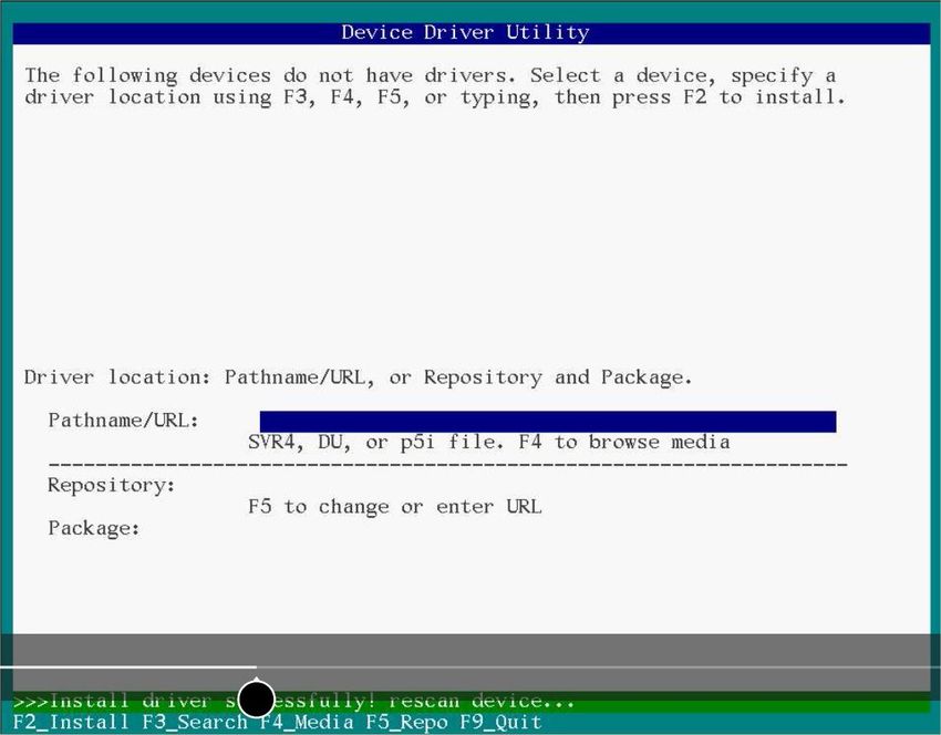
6.10.1 Installing with Solaris Live Media.....................................................................................................37
6.10.2 Installing with Solaris Text Installer..................................................................................................38
6.11 Installing with Citrix XenServer ......................................................................................................................40
6.12 Installing with VMware ..................................................................................................................................40
7 Installing the Driver on an Existing Operating System.....................................................................42
7.1 Download the Driver Package...........................................................................................................................42
7.2 Creating a Driver Disk.......................................................................................................................................42
7.3 Installing on Windows ......................................................................................................................................42
7.4 Installing on Red Hat or CentOS........................................................................................................................43
7.5 Installing on SuSE Linux Enterprise Server........................................................................................................44
7.6 Installing on Oracle Linux..................................................................................................................................45
7.7 Installing on Ubuntu Linux................................................................................................................................46
7.8 Installing on Debian Linux.................................................................................................................................47
7.9 Installing on FreeBSD........................................................................................................................................47
7.10 Installing on Solaris.........................................................................................................................................48
7.11 Installing on Citrix XenServer..........................................................................................................................49
7.12 Installing on VMware......................................................................................................................................50
8 Solving Problems ............................................................................................................................51
8.1 Troubleshooting Checklist.................................................................................................................................51
8.2 Resetting the Adapter ......................................................................................................................................51
Appendix A Using the Microsemi SAS/SATA Configuration Utility......................................................52
A.1 Running the Microsemi SAS/SATA Configuration Utility: Ctrl-A or UEFI/HII?...................................................52
A.2 Controller Information.....................................................................................................................................53
A.3 Creating an Array..............................................................................................................................................53
A.4 Creating a maxCache Array..............................................................................................................................53
A.5 Managing Arrays and Logical Drives.................................................................................................................54
A.5.1 Viewing Logical Drive Properties.......................................................................................................54
A.5.2 Creating Logical Drives......................................................................................................................54
A.5.3 Enabling IO Bypass.............................................................................................................................55
A.5.4 Editing Logical Drive Properties.........................................................................................................55
A.5.5 Deleting a Logical Drive.....................................................................................................................55
A.5.6 Assigning Spares................................................................................................................................56
A.5.7 Deleting a Spare Drive.......................................................................................................................56
A.5.8 Identifying the Drives in an Array......................................................................................................56
A.5.9 Deleting an Array...............................................................................................................................57
A.6 Modifying SmartHBA 2100/SmartRAID 3100 controller Settings.....................................................................57
A.7 Clearing the Controller Configuration..............................................................................................................59
A.8 Backup Power Source.......................................................................................................................................59
A.9 Managing Power Settings.................................................................................................................................59
A.10 Out of Band Messaging Settings.....................................................................................................................60
A.11 Using the Encryption Manager.......................................................................................................................61
A.11.1 Encryption Manager Full Setup.......................................................................................................61
A.11.2 Modifying the Encryption Manager Configuration..........................................................................62
A.11.3 Modifying User Account Settings....................................................................................................63
A.11.4 Resetting a Forgotten Password......................................................................................................63
A.11.5 Clearing the Encryption Manager Configuration.............................................................................64
A.11.6 Re-Keying a Logical Drive.................................................................................................................64
Microsemi Proprietary and Confidential Installation and User Guide Revision 8 ixContents
A.11.7 Converting Plaintext Data to Encrypted Data..................................................................................64
A.11.8 Erasing an Encrypted Logical Drive..................................................................................................65
A.11.9 Importing a Foreign Master Key......................................................................................................65
A.12 Configuring the Controller Port Mode............................................................................................................66
A.13 Device Information.........................................................................................................................................66
A.14 Identifying a Disk Drive...................................................................................................................................66
A.15 Erasing a Disk Drive........................................................................................................................................67
A.16 Updating Drive Firmware...............................................................................................................................67
A.17 Clearing Configuration Meta-data..................................................................................................................68
A.18 Setting the Bootable Device(s) for Legacy Boot Mode...................................................................................68
A.19 Updating the SmartHBA 2100/SmartRAID 3100 controller Firmware............................................................69
A.20 Creating a Support Archive.............................................................................................................................69
A.21 Resetting the Controller to Factory Defaults..................................................................................................69
Appendix B Installing the SmartPQI Drivers from Source ..................................................................71
B.1 Installation Instructions for Supported Linux OS's............................................................................................71
B.2 Using the Installation DVD as the Repository...................................................................................................73
Appendix C SmartRAID/SmartHBA Physical and Logical Device Support...........................................75
Appendix D Safety Information..........................................................................................................76
D.1 Electrostatic Discharge (ESD)............................................................................................................................76
Appendix E Technical Specifications...................................................................................................77
E.1 Environmental Specifications............................................................................................................................77
E.2 DC Power Requirements...................................................................................................................................77
E.3 Current and Power Requirements ...................................................................................................................77
Microsemi Proprietary and Confidential Installation and User Guide Revision 8 xAbout This Guide
1 About This Guide
This Installation and User's Guide explains how to install and setup your Adaptec® SmartRAID 3100 or
SmartHBA 2100 Series Host Bus Adapter, including driver installation, BIOS operations, troubleshooting
tips, and instructions for flashing the adapter firmware.
These SmartRAID 3100 Series adapter models are described in this guide:
• Adaptec SmartRAID 3101-4i
• Adaptec SmartRAID 3101E-4i
• Adaptec SmartRAID 3151-4i
• Adaptec SmartRAID 3102-8i
• Adaptec SmartRAID 3102E-8i
• Adaptec SmartRAID 3152-8i
• Adaptec SmartRAID 3154-8i
• Adaptec SmartRAID 3154-8e
• Adaptec SmartRAID 3154-16i
• Adaptec SmartRAID 3154-24i
• Adaptec SmartRAID 3154-8i8e
• Adaptec SmartRAID 3154-8i16e
• Adaptec SmartRAID 3162-8i
• Adaptec SmartRAID 3162-8i /e
These SmartHBA 2100 Series adapter models are described in this guide:
• Adaptec SmartHBA 2100-8i
• Adaptec SmartHBA 2100-4i4e
• Adaptec SmartHBA 2100-8i8e
• Adaptec SmartHBA 2100-16i
• Adaptec SmartHBA 2100-24i
1.1 What You Need to Know Before You Begin
This guide is written for data storage and IT professionals who are responsible for installing, configuring,
and maintaining SmartRAID 3100 Series and SmartHBA 2100 Series Host Bus Adapters in computers or
servers in a "cloud" or data center environment. You should be familiar with computer hardware, operating
system administration, data storage devices, and SAS and Serial ATA (SATA) technology.
If you are responsible for configuring the storage resources on the SmartRAID and SmartHBA adapters, you
should be familiar with RAID technology and creating bootable volumes.
1.2 Terminology Used in this Guide
Many of the terms and concepts referred to in this guide are known to computer users by multiple names.
This guide uses these terms:
• Host Bus Adapter or HBA (also known as controller, adapter, or I/O card)
• Disk drive (also known as hard disk, hard drive, or hard disk drive)
• Solid State Drive (also known as SSD or non-rotating storage media)
• Enclosure (also known as a storage enclosure, disk drive enclosure, or JBOD)
Microsemi Proprietary and Confidential Installation and User Guide Revision 8 1About This Guide
1.3 How to Find More Information
You can find more information about your SmartRAID 3100 Series or SmartHBA 2100 Series Host Bus Adapter
by referring to these documents.
• ARCCONF Command Line Utility User's Guide for Adaptec Smart Storage Controllers—Describes how
to use the ARCCONF utility to perform configuration and storage management tasks from an interactive
command line. (ESC-2161615)
• Adaptec SmartRAID 3100 Series and SmartHBA 2100 Series Host Bus Adapters Installation and User's
Guide (this manual)—Describes how to install SmartRAID 3100 and SmartHBA 2100 Series adapters in
a computer or server, install drivers, and configure the adapter for initial use. (ESC-2171547)
• Adaptec Flash Backup Module ASCM-35 Installation Instructions—Describes how to install the ASCM-35
Flash Backup module using the mounting plate method. (ESC-2170352)
• Adaptec SmartRAID 3100 and SmartHBA 2100 Software/Firmware Release Notes—Includes updated
product information, known issues, and limitations. (ESC-2161026)
Microsemi Proprietary and Confidential Installation and User Guide Revision 8 2Kit Contents and System Requirements
2 Kit Contents and System Requirements
This section lists the contents of your SmartRAID 3100 Series or SmartHBA 2100 Series kit and the system
requirements for successfully installing and using your adapter.
2.1 Kit Contents
SmartRAID 3100 Series kits:
• SmartRAID 3100 Series adapter
• Full-height ("FH") and Low-profile ("LP") brackets, with mounting screws
• ASCM-35F Supercap Module, including:
◦ Supercap module extension cable
◦ Full-height and Low-profile mounting plate, with mounting screws
◦ Supercap mounting clip
◦ Tie-wraps (nylon)
SmartHBA 2100 Series kits:
• SmartHBA 2100 Series adapter
• Full-height ("FH") and Low-profile ("LP") brackets, with mounting screws
Note: The latest firmware, drivers, utilities software, and documentation can be
downloaded at storage.microsemi.com. For more information, see Downloading the Driver
Package.
2.2 System Requirements
• PC-compatible computer with Intel Pentium, or equivalent, processor
• 4 GB of RAM minimum
• Available compatible PCIe slot (depending on your adapter model—see the descriptions in About Your
Host Bus Adapter)
• One of these operating systems:
◦ Microsoft® Windows® Server, Windows 10, Windows 8.1, Windows 7
◦ Red Hat® Enterprise Linux
◦ CentOS
◦ SuSE Linux Enterprise Server
◦ Ubuntu Linux
◦ Debian Linux
◦ Oracle Linux
◦ Citrix Xenserver
◦ Solaris
◦ FreeBSD
◦ VMware ESXi
See the Release Notes for a complete list of supported OS versions.
• USB flash drive or CD burner, for creating driver disks and bootable media
Microsemi Proprietary and Confidential Installation and User Guide Revision 8 3About Your SmartRAID 3100 Series Host Bus Adapter
3 About Your SmartRAID 3100 Series Host Bus Adapter
This section provides an overview of the features of the SmartRAID 3100 Series adapter.
3.1 Standard Features
• Support for SAS and SATA Hard Disk Drives (HDD) and Solid State Drives (SSD)
• UEFI pre-boot BIOS, CTRL-A configuration utility
• Flash ROM for updates to firmware and BIOS
• Up to 24 ports, 12 Gb/s I/O
• SAS 3.0, PCIe 3.0
• Low-profile MD2 form factor
• Mini-SAS HD connectors
• Cache protection with supercapacitor module
• maxCrypto Controller-Based Encryption (CBE) (SmartRAID 3162-8i /e only)
• Support for disk drive enclosures with SES2 enclosure management hardware
• Thermal sensor, with logging capabilities
• GUI and CLI management utilities
• Support for RAID 0, 1, 5, 6, 10, 50, 60
• Universal asynchronous receiver/transmitter (UART) debug/diagnostic port
Note: See the Product Brief for a complete list of supported features.
3.2 Mechanical Information
3.2.1 Board Dimensions
This table shows the board dimensions of the SmartRAID 3100 Series adapter, in inches.
Table 1 • SmartRAID 3100 Series Board Dimensions
Dimension Measure
Height 2.700"
Length 6.600"
PCB Thickness 0.062"
Max Component Height, Top Side 0.570"
Max Component Height, Bottom Side 0.105"
3.2.2 Heat Sink
SmartRAID 3100 Series adapters include a passive heat sink. The heat sink does not support an optional
fan. The heat sink has four push-pins located at its four corners to ensure an even distribution of force
across the top of the ASIC. For airflow requirements, see Environmental Specifications on page 77.
Microsemi Proprietary and Confidential Installation and User Guide Revision 8 4About Your SmartRAID 3100 Series Host Bus Adapter
3.3 Visual Indicators
LEDs on SmartRAID 3100 Series adapters provide a visual indication of the board hardware status and cache
backup system. The LED locations vary, and may be on the front of the board or back of the board (see
SmartRAID 3100 Series LED Locations on page 5), and include DDR LEDs (also referred to as Flash-Based
Write Cache, or FBWC, LEDs) and status LEDs. The LED states are described in Table 2 • SmartRAID 3100
Series Status LEDs on page 5 and Table 3 • SmartRAID 3100 Series DDR/FBWC LED States on page 6.
Front panel brackets on SmartRAID 3100-4i/8i controllers have three holes for the Heartbeat LED, Fault
LED, and Crypto LED.
Figure 1 • SmartRAID 3100 Series LED Locations
Table 2 • SmartRAID 3100 Series Status LEDs
LED Color Meaning
DDR_LED1 Yellow Cache backup error (see Table 3 • SmartRAID 3100 Series DDR/FBWC
LED States on page 6)
DDR_LED2 Green Dirty cache (see Table 3 • SmartRAID 3100 Series DDR/FBWC LED States
on page 6)
DDR_LED3 Green Charge status (see Table 3 • SmartRAID 3100 Series DDR/FBWC LED
States on page 6)
HEARTBEAT Green Heartbeat (blinks once per/second when firmware operating normally)
FAULT Yellow Hardware Lockup/Fault
CRYPTO Green Cryptographic State: Off = NON-ENCRYPTING, On = ENCRYPTING
Microsemi Proprietary and Confidential Installation and User Guide Revision 8 5About Your SmartRAID 3100 Series Host Bus Adapter
LED Color Meaning
AVS_ENB Green The controller is operating normally if this LED is on or off: On = Adaptive
Voltage Scaling (AVS) Enabled, Off = Adaptive Voltage Scaling (AVS) Dis-
abled
Note: Not supported on SmartRAID 3100-16i
and SmartRAID 3100-24i adapters.
PAL_DEBUG Yellow (8i/8e adapters) Debug LED control signal
Red (16i/24i adapters)
Table 3 • SmartRAID 3100 Series DDR/FBWC LED States
Cache Status DDR_LED1 (Yel- DDR_LED2 (G- DDR_LED3 (Green) Meaning/Comments
low) reen)
Power-ON state Off 1 Hz 1 Hz Power-up
Not Charged Off Off 1 Hz Backup power not ready
Battery Charged / not Off Off On Backup power ready, no dirty cache
dirty
Battery Charged / dirty Off On On Backup power ready, dirty cache
No Battery On On On Cache error / Battery not connected
Over Temperature 1 Hz On Off Over temperature
Backup in Progress Off 1Hz Off Backup State
Backup in Flash Off On 1Hz Backup State Cont. State
Backup Complete Off On Off Backup complete state
Charge Timeout 2 Hz 2 Hz On Battery charge timeout
General Error On On On Cache Error
Backup Incomplete 1 Hz 1 Hz Off Idle State & BDtF & brownout & bad volt
Backup/restore Error On On Off Backup complete state, restore error
Microsemi Proprietary and Confidential Installation and User Guide Revision 8 6About Your SmartRAID 3100 Series Host Bus Adapter
3.4 About the Adaptec SmartRAID 3101-4i/3151-4i
The Adaptec SmartRAID 3101-4i/3151-4i is a SAS Host Bus Adapter with these features:
Figure 2 • Adaptec SmartRAID 31x1-4i
Form Factor Low-profile MD2
Bus compatibility PCIe 3.0
PCIe bus width x8
Data transfer rate 12 Gb/s per port
Phys (Unified Serial Ports) 4
Standard memory 32 MB Boot Flash, 256 Kb SEEPROM, 1Mb MRAM
Cache 1 GB
Connectors, internal 1 mini-SAS HD x4 (SFF-8643)
Maximum number of disk drives 4 direct-attached (or up to 238 with expanders)
Enclosure Support SES2, SES3, IBPI and SGPIO
Encryption No
Thermal sensor Inlet ambient temperature, ASIC die temperature, Top-side board ambient tem-
perature, Bottom-side board ambient temperature
Cache Protection/Backup SmartRAID 3101-4i: No (non-upgradeable)
SmartRAID 3151-4i: Integrated ASCM-35F backup module with external superca-
pacitor
Microsemi Proprietary and Confidential Installation and User Guide Revision 8 7About Your SmartRAID 3100 Series Host Bus Adapter
3.5 About the Adaptec SmartRAID 3101E-4i
The Adaptec SmartRAID 3101E-4i is a SAS Host Bus Adapter with these features:
Figure 3 • Adaptec SmartRAID 3101E-4i
4
2
3
1
4i
1E-
310
RAID
art
Sm
1 Mounting Bracket
2 HDA mode jumper
3 UART
4 Internal mini-SAS
5 HD connector (CN0)
5 PCIe x8 Connector
Form Factor Low-profile MD2
Bus compatibility PCIe 3.0
PCIe bus width x8
Data transfer rate 12 Gb/s per port
Phys (Unified Serial Ports) 4
Standard memory 32 MB Boot Flash, 256 Kb SEEPROM, 1Mb MRAM
Cache 1 GB
Connectors, internal 1 mini-SAS HD x4 (SFF-8643)
Maximum number of disk drives 4 direct-attached
Enclosure Support SES2, SES3, IBPI and SGPIO
Expander Support No (no drives of any type detected if connected via expander)
Encryption No
Thermal sensor Inlet ambient temperature, ASIC die temperature, Top-side board ambient tem-
perature, Bottom-side board ambient temperature
Cache Protection/Backup No (non-upgradeable)
Microsemi Proprietary and Confidential Installation and User Guide Revision 8 8About Your SmartRAID 3100 Series Host Bus Adapter
3.6 About the Adaptec SmartRAID 3102-8i/3152-8i/3154-8i
The Adaptec SmartRAID 3102-8i/3152-8i/3154-8i is a SAS Host Bus Adapter with these features:
Figure 4 • Adaptec SmartRAID 31xx-8i
Form Factor Low-profile MD2
Bus compatibility PCIe 3.0
PCIe bus width x8
Data transfer rate 12 Gb/s per port
Phys (Unified Serial Ports) 8
Standard memory 32 MB Boot Flash, 256 Kb SEEPROM, 1Mb MRAM
Cache SmartRAID 3102-8i/3152-8i: 2 GB
SmartRAID 3154-8i: 4 GB
Connectors, internal 2 mini-SAS HD x4 (SFF-8643)
Maximum number of disk drives 8 direct-attached (or up to 246 with expanders)
Enclosure Support SES2, SES3, IBPI and SGPIO
Encryption No
Thermal sensor Inlet ambient temperature, ASIC die temperature, Top-side board ambient tem-
perature, Bottom-side board ambient temperature
Cache Protection/Backup SmartRAID 3102-8i: No (non-upgradeable)
SmartRAID 3152-8i/3154-8i: Integrated ASCM-35F backup module with external
supercapacitor
Microsemi Proprietary and Confidential Installation and User Guide Revision 8 9About Your SmartRAID 3100 Series Host Bus Adapter
3.7 About the Adaptec SmartRAID 3102E-8i
The Adaptec SmartRAID 3102E-8i is a SAS Host Bus Adapter with these features:
Figure 5 • Adaptec SmartRAID 3102E-8i
4
2
3
1
8i
2E-
310
RAID
art
Sm
1 Mounting Bracket
2 HDA mode jumper
3 UART
4 Internal mini-SAS
5 HD connectors (CN0, CN1)
5 PCIe x8 Connector
Form Factor Low-profile MD2
Bus compatibility PCIe 3.0
PCIe bus width x8
Data transfer rate 12 Gb/s per port
Phys (Unified Serial Ports) 8
Standard memory 32 MB Boot Flash, 256 Kb SEEPROM, 1Mb MRAM
Cache 2 GB
Connectors, internal 2 mini-SAS HD x4 (SFF-8643)
Maximum number of disk drives 8 direct-attached
Enclosure support SES2, SES3, IBPI and SGPIO
Expander support No (no drives of any type detected if connected via expander)
Encryption No
Thermal sensor Inlet ambient temperature, ASIC die temperature, Top-side board ambient tem-
perature, Bottom-side board ambient temperature
Cache Protection/Backup No (non-upgradeable)
Microsemi Proprietary and Confidential Installation and User Guide Revision 8 10About Your SmartRAID 3100 Series Host Bus Adapter
3.8 About the Adaptec SmartRAID 3154-8e
The Adaptec SmartRAID 3154-8e is a SAS Host Bus Adapter with these features:
Figure 6 • Adaptec SmartRAID 3154-8e
Form Factor Low-profile MD2
Bus compatibility PCIe 3.0
PCIe bus width x8
Data transfer rate 12 Gb/s per port
Phys (Unified Serial Ports) 8
Standard memory 32 MB Boot Flash, 256 Kb SEEPROM, 1 Mb MRAM
Cache 4 GB
Connectors, external 2 mini-SAS HD x4 (SFF-8644)
Maximum number of disk drives 8 direct-attached (or up to 254 with expanders)
Enclosure Support SES2, SES3, IBPI and SGPIO
Encryption No
Thermal sensor Inlet ambient temperature, ASIC die temperature, Top-side board ambient tem-
perature, Bottom-side board ambient temperature
Cache Protection/Backup Integrated ASCM-35F backup module with external supercapacitor
Microsemi Proprietary and Confidential Installation and User Guide Revision 8 11About Your SmartRAID 3100 Series Host Bus Adapter
3.9 About the Adaptec SmartRAID 3154-8i8e
The Adaptec SmartRAID 3154-8i8e is a SAS Host Bus Adapter with these features:
Figure 7 • Adaptec SmartRAID 3154-8i8e
Form Factor Low-profile MD2
Bus compatibility PCIe 3.0
PCIe bus width x8
Data transfer rate 12 Gb/s per port
Phys (Unified Serial Ports) 16
Standard memory 32 MB Boot Flash, 128 Kb SEEPROM, 128 KB MRAM
Cache 4 GB
Connectors, internal 2 mini SAS HD x4 (SFF-8644) and 2 mini SAS HD x4 (SFF-8643)
Maximum number of disk drives 16 direct-attached (or up to 246 with expanders)
Enclosure Support SES2, SES3, IBPI and SGPIO
Thermal sensor Processor temperature, Ambient temperature
Cache Protection/Backup Integrated ASCM-35F backup module with external supercapacitor
Microsemi Proprietary and Confidential Installation and User Guide Revision 8 12About Your SmartRAID 3100 Series Host Bus Adapter
3.10 About the Adaptec SmartRAID 3154-8i16e
The Adaptec SmartRAID 3154-8i16e is a SAS Host Bus Adapter with these features:
Figure 8 • Adaptec SmartRAID 3154-8i16e
Form Factor Low-profile MD2
Bus compatibility PCIe 3.0
PCIe bus width x8
Data transfer rate 12 Gb/s per port
Phys (Unified Serial Ports) 24
Standard memory 32 MB boot flash, 128 Kb SEEPROM, 128 KB MRAM
Cache 4 GB
Connectors, internal 4 mini SAS HD x4 (SFF-8644) and 2 mini SAS HD x4 (SFF-8643)
Maximum number of disk drives 24 direct-attached (or up to 246 with expanders)
Enclosure Support SES2, SES3, IBPI and SGPIO
Thermal sensor Processor temperature, Ambient temperature
Cache Protection/Backup Integrated ASCM-35F backup module with external supercapacitor
Microsemi Proprietary and Confidential Installation and User Guide Revision 8 13About Your SmartRAID 3100 Series Host Bus Adapter
3.11 About the Adaptec SmartRAID 3154-16i
The Adaptec SmartRAID 3154-16i is a SAS Host Bus Adapter with these features:
Figure 9 • Adaptec SmartRAID 3154-16i
Form Factor Low-profile MD2
Bus compatibility PCIe 3.0
PCIe bus width x8
Data transfer rate 12 Gb/s per port
Phys (Unified Serial Ports) 16
Standard memory 32 MB boot flash, 128 Kb SEEPROM, 128 KB MRAM
Cache 4 GB
Connectors, internal 4 mini-SAS HD x4 (SFF-8643)
Maximum number of disk drives 16 direct-attached (or up to 238 with expanders)
Enclosure Support SES2, SES3, IBPI and SGPIO
Thermal sensor Processor temperature, Ambient temperature
Cache Protection/Backup Integrated ASCM-35F backup module with external supercapacitor
Microsemi Proprietary and Confidential Installation and User Guide Revision 8 14About Your SmartRAID 3100 Series Host Bus Adapter
3.12 About the Adaptec SmartRAID 3154-24i
The Adaptec SmartRAID 3154-24i is a SAS Host Bus Adapter with these features:
Figure 10 • Adaptec SmartRAID 3154-24i
5
3
4
2
i
-24
154
1 D3
RAI
art
Sm
1 Mounting Bracket
2 UART
3 Supercapacitor Connector
4 2 internal mini-SAS
6 HD connectors (CN4–CN5)
5 4 internal mini-SAS
HD connectors (CN0–CN3)
7 6 PCIe x8 Connector
7 HDA mode jumper
Form Factor Low-profile MD2
Bus compatibility PCIe 3.0
PCIe bus width x8
Data transfer rate 12 Gb/s per port
Phys (Unified Serial Ports) 24
Standard memory 32 MB Boot Flash, 128 Kb SEEPROM, 128 KB MRAM
Cache 4 GB
Connectors, internal 6 mini-SAS HD x4 (SFF-8643)
Maximum number of disk drives 24 direct-attached (or up to 230 with expanders)
Enclosure Support SES2, SES3, IBPI and SGPIO
Thermal sensor Processor temperature, Ambient temperature
Cache Protection/Backup Integrated ASCM-35F backup module with external supercapacitor
Microsemi Proprietary and Confidential Installation and User Guide Revision 8 15About Your SmartRAID 3100 Series Host Bus Adapter
3.13 About the SmartRAID 3162-8i/SmartRAID 3162-8i /e Adapter
The SmartRAID 3162-8i/SmartRAID 3162-8i /e is a SAS Host Bus Adapter with these features:
Figure 11 • Adaptec SmartRAID 3162-8i
Form Factor Low-profile MD2
Bus compatibility PCIe 3.0
PCIe bus width x8
Data transfer rate 12 Gb/s per port
Phys (Unified Serial Ports) 8
Standard memory 32 MB Boot Flash, 16 KB Boot SEEPROM, 128 KB MRAM, 256 KB Crypto SEEPRO-
M (SmartRAID 3162-8i /e only)
Cache 2 GB
Connectors, internal 2 mini-SAS HD x4 (SFF-8643)
Maximum number of disk drives 8 direct-attached (or up to 246 with expanders)
Enclosure Support SES2, SES3, IBPI and SGPIO
maxCrypto Controller-Based Encryption SmartRAID 3162-8i: No
SmartRAID 3162-8i /e: Yes
Thermal sensor Processor temperature, Ambient temperature
Cache Protection/Backup Integrated flash backup module ASCM-17F, with board-mounted supercapacitor
Microsemi Proprietary and Confidential Installation and User Guide Revision 8 16About Your SmartHBA 2100 Series Host Bus Adapter
4 About Your SmartHBA 2100 Series Host Bus Adapter
This section provides an overview of the features of the SmartHBA 2100 Series adapter.
4.1 Standard Features
• Support for SAS and SATA Hard Disk Drives (HDD) and Solid State Drives (SSD)
• UEFI pre-boot BIOS, CTRL-A configuration utility
• Flash ROM for updates to firmware and BIOS
• Up-to 24 ports, 12 Gbps I/O
• SAS 3.0, PCIe 3.0
• Low-profile MD2 form factor
• Mini-SAS HD connectors
• Support for disk drive enclosures with SES 2.x/3.x inband support, TWI, IBPI and SGPIO enclosure
management
• Thermal sensors, with logging capabilities
• Support for RAID 0, 1, 5, 10
4.2 Mechanical Information
4.2.1 Board Dimensions
This table shows the board dimensions of the SmartHBA 2100 Series adapters, in inches.
Table 4 • SmartHBA 2100 Series Board Dimensions
Dimension SmartHBA 2100-4i4e SmartHBA 2100-8i
Height 2.70" 2.712"
Length 5.20" 6.60"
PCB Thickness 0.062" 0.062"
Max Component Height, Top Side 0.570" 0.570"
Max Component Height, Bottom Side 0.105" 0.105"
4.2.2 Heat Sink
SmartHBA 2100 Series adapters include a passive heat sink capable of bi-directional airflow. The heat sink
does not support an optional fan. The heat sink has four push-pins located at its four corners to ensure an
even distribution of force across the top of the ASIC. For airflow requirements, see Environmental
Specifications.
Microsemi Proprietary and Confidential Installation and User Guide Revision 8 17About Your SmartHBA 2100 Series Host Bus Adapter
4.3 Visual Indicators
LEDs on the SmartHBA 2100 Series adapters provide a visual indication of the board hardware status. The
LED locations vary, and may be on the front of the board or back of the board (see SmartHBA 2100 Series
LED Locations on page 18). The LED states are described in Table 5 • SmartHBA 2100 Series Status LEDs on
page 18.
Figure 12 • SmartHBA 2100 Series LED Locations
Table 5 • SmartHBA 2100 Series Status LEDs
LED Color Meaning
HEARTBEAT (DS5) Green Heartbeat (blinks once per second when firmware is operating normally)
FAULT (DS7) Yellow Hardware Lockup/Fault
CRYPTO (DS1) Green Cryptographic State: always off. SmartHBA 2100 Series adapters do
not support encryption.
AVS_ENB (DS2) Green On=Adaptive Voltage Scaling (AVS) enabled, Off=Adaptive Voltage Scal-
ing (AVS) disabled
PAL_DEBUG (DS10) Red Debug LED control signal
Microsemi Proprietary and Confidential Installation and User Guide Revision 8 18You can also read