BioSmart Integration Module Configuration and Operation Manual - Last update 08/04/2021
←
→
Page content transcription
If your browser does not render page correctly, please read the page content below
BioSmart Integration Module Configuration and Operation
                        Manual

                     Last update 08/04/2021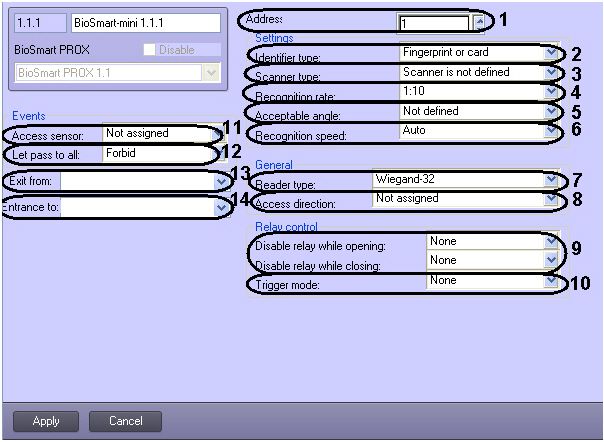
ACFA Intellect – BioSmart Integration Module Configuration and Operation Manual

Table of contents
1      List of terms used in BioSmart Integration Module Configuration and Operation Manual ....3
2      Introduction into BioSmart Integration Module Configuration and Operation Manual.........4
2.1 Purpose of the Document........................................................................................................................ 4
2.2 General information about BioSmart module ....................................................................................... 4
3      Supported hardware and licensing of the BIOSMART integration module .............................5
4      Configuring BioSmart integration module ................................................................................7
4.1 Configuration procedure for BioSmart integration module.................................................................. 7
4.2 Configuring connection of BioSmart ACS controllers............................................................................ 7
4.3 Configuring BioSmart 4 controller .......................................................................................................... 9
4.3.1 Configuring walk-through parameters of BioSmart 4 controller ........................................................................... 9
4.3.2 Configuring BioSmart 4 controller working with external hardware................................................................... 10
4.3.3 Configuring relay of BioSmart 4 controller............................................................................................................ 11
4.3.4 Configuring access sensor of BioSmart 4 controller ............................................................................................. 12
4.3.5 Configuring operating scenarios for executive devices of BioSmart 4 controller ............................................... 12
4.4 Configuring BioSmart PROX v.2 and BioSmart PROX-E controllers.................................................... 13
4.4.1 Configuring access parameters.............................................................................................................................. 13
4.4.2 Configuring operation mode of controller ............................................................................................................ 14
4.4.3 Configuring discrete and alarm inputs of controller............................................................................................. 14
4.5 Configuring BioSmart-mini reader........................................................................................................ 15
4.6 Configuring BioSmart reader (all models)............................................................................................ 17
4.7 Sending configuration to controller ..................................................................................................... 17
4.8 Writing the VMS data to controller........................................................................................................ 17
4.9 Managing the BioSmart fingerprints..................................................................................................... 18
5      Working with BioSmart integration module ...........................................................................22
5.1 General information about how to work with BioSmart integration module .................................... 22
5.2 Managing BioSmart controllers ............................................................................................................ 22

                                                                                                                                                                – 2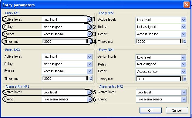
BioSmart Integration Module Configuration and Operation Manual

1 List of terms used in BioSmart Integration Module Configuration and Operation
  Manual
Access – movement of people, means of transport and other objects into (out of) premises, buildings, zones and territories.
Access control system (ACS) – hardware-software system performing the access control functions.
Biometric scanner – an electronic device used to capture and transmit fingerprint images for further identification.
Executive devices – turnstiles, gates, barriers or doors equipped with electromagnetic or electromechanical locks.
Mifare card – Mifare standard contactless card containing fingerprint template.

                                               List of terms used in BioSmart Integration Module Configuration and Operation Manual – 3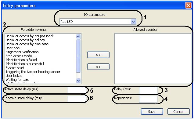
BioSmart Integration Module Configuration and Operation Manual

2 Introduction into BioSmart Integration Module Configuration and Operation
  Manual

  On the page:

        • Purpose of the Document
        • General information about BioSmart module

2.1 Purpose of the Document
Configuration and operation manual for BioSmart integration module is a reference and information guide meant for BioSmart
configuration specialists. This module is a part of ACFA Intellect software package.
The guide provides:
   1. general information about BioSmart ACS module;
   2. information about how to configure BioSmart ACS module;
   3. information about how to work with BioSmart ACS module.

2.2 General information about BioSmart module
BioSmart module is the ACFA Intellect-based ACS component. It performs the following functions:
   1. Configuring BioSmart ACS (manufactured by ProSoft Biometrics);
   2. Ensuring interaction between BioSmart ACS and ACFA Intellect (monitoring, control).

        Note.
        For more information about BioSmart ACS, please refer to official documentation for this system.

As this guide being prepared, the following equipment has been integrated with ACFA Intellect:
    •   BioSmart Prox v.2 controller.
    •   BioSmart Prox-E controller.
    •   BioSmart 4 controller (all models).
    •   BioSmart-mini reader.
    •   BioSmart readers (all models).
Before configuring BioSmart module do the following:
   1. Install BioSmart ACS hardware on the site under security surveillance (see reference documentation about BioSmart ACS);
   2. Connect BioSmart ACS to ACFA Intellect Server (see reference documentation about BioSmart ACS).

                                                 Introduction into BioSmart Integration Module Configuration and Operation Manual – 4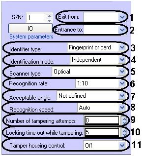
BioSmart Integration Module Configuration and Operation Manual

3 Supported hardware and licensing of the BIOSMART integration module
 Manufacturer                Prosoft-Biometrics Ltd.
                             https://www.biosmart-tech.com/

 Integration type            Low-level protocol

 Equipment connection        RS-232, USB, Ethernet

Supported equipment

 Equipment                                            Function                                     Features

 PROX-E                                               Independent access controller                Cards: 16000
                                                                                                   Maximal number of users by fingerprints for one
                                                                                                   BioSmart Mini reader: 100
                                                                                                   Max. number of events:100 000
                                                                                                   Identification time 1:3 000 not more 1 sec
                                                                                                   Number of reader devices 4
                                                                                                   Number of outputs (Wiegand or discrete output) 2
                                                                                                   Number of discrete inputs 6
                                                                                                   Time zones 64 (5 intervals for each day, 32 holidays)
                                                                                                   "Gate" mode - two-cycle mode with stopping for
                                                                                                   check incoming
                                                                                                   Antipassbach
                                                                                                   Pass with attendant
                                                                                                   Multi-users identification
                                                                                                   Door locking while arming
                                                                                                   Doors unlocking while fire alarm
                                                                                                   Ethernet interface

 PROX v.2                                             Independent access controller                Cards: 3000
                                                                                                   Maximal number of users by fingerprints for one
                                                                                                   BioSmart Mini reader: 100
                                                                                                   Max. number of events:40 000
                                                                                                   Identification time 1:3 000 not more 1 sec
                                                                                                   Number of reader devices 4
                                                                                                   Number of outputs (Wiegand or discrete output) 2
                                                                                                   Number of inputs (Wiegand or LED indication) 2
                                                                                                   Number of discrete inputs 6
                                                                                                   Time zones 64 (5 intervals for each day, 32 holidays)
                                                                                                   "Gate" mode - two-cycle mode with stopping for
                                                                                                   check incoming
                                                                                                   Antipassbach
                                                                                                   Pass with attendant
                                                                                                   Multi-users identification
                                                                                                   Door locking while arming
                                                                                                   Doors unlocking while fire alarm
                                                                                                   Ethernet interface

 Biosmart 4 (all modifications)                       Fingerprint scanner/Access controller        Max. number of fingerprints in local mode 500
                                                                                                   Max. number of fingerprints in server mode 3000
                                                                                                   Maximal number of users in the card+finger mode
                                                                                                   3000
                                                                                                   Max. number of cards in local mode 3000
                                                                                                   Max. number of events 40000
                                                                                                   Time zones
                                                                                                   64 time groups (5 intervals for each day, 32 holidays)
                                                                                                   Capacity (SteelCoat)/optical fingerprint scanner
                                                                                                   Embedded EM-Marine cards reader
                                                                                                   RS-485, Ethernet interfaces

 Biosmart-mini                                        Card and fingerprint reader                  Max. number of users for identification by fingerprints
                                                                                                   (up to 5 fingerprints for each user) 100
                                                                                                   Max. number of cards 100
                                                                                                   RS-485 interface

                                                                      Supported hardware and licensing of the BIOSMART integration module – 5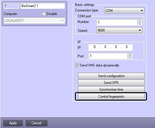
BioSmart Integration Module Configuration and Operation Manual

 Equipment                                            Function                                    Features

 BioSmart FS80                                        Сontrol fingerprint reader                  Fingerprint scanner Optical
 Note. Configuring and working with this reader
 module is described in the section Control Readers
 Settings Guide

Protection
1 COM port or 1 IP-address.

                                                                      Supported hardware and licensing of the BIOSMART integration module – 6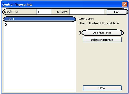
BioSmart Integration Module Configuration and Operation Manual

4 Configuring BioSmart integration module

4.1 Configuration procedure for BioSmart integration module
Here is the configuration procedure for BioSmart integration module:
   1. Configure connection of BioSmart ACS controllers.
   2. Configure BioSmart ACS controllers.
   3. Configure BioSmart ACS readers.

4.2 Configuring connection of BioSmart ACS controllers
Connection of BioSmart ACS controllers of all types is configured the same way.
BioSmart ACS controller is connected to ACFA Intellect as follows:
   1. Create the Computer (LOCALHOST)-based BioSmart2 object in the Hardware tab of the System settings dialog box.
      Each controller corresponds to the BioSmart2 object.

                                                                                        Configuring BioSmart integration module – 7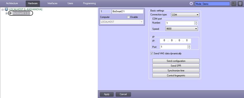
BioSmart Integration Module Configuration and Operation Manual

2. Go to the settings panel of the BioSmart2 object.

3.   Select the controller connection type in the corresponding list (1).
4.   If connection is performed via RS-485 standard, then specify the COM port number and speed of its connection (2).
5.   If connection is performed via Ethernet standard, then specify IP address and controller port (3).
6.   Click the Apply button to save all changes.
7.   Create the Biosmart 4 or BioSmart PROX (BioSmart PROX v.2 controller corresponds to this object if connection is
     performed via RS-485 standard BioSmart PROX-E controller if connection is performed via Ethernet standard) controller
     object on the base of the BioSmart2 object.

                                                                                    Configuring BioSmart integration module – 8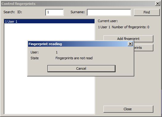
BioSmart Integration Module Configuration and Operation Manual
8. On the settings panel of the created object specify the serial number of controller BioSmart ACS.
9. Click the Apply button.
Note.
Only one server (Intellect or Biosmart software) can be connected to a controller at a time. If some software has
connected to the controller, other servers are not able to establish connection.
BioSmart ACS controller is now connected to ACFA Intellect.
4.3 Configuring BioSmart 4 controller
4.3.1 Configuring walk-through parameters of BioSmart 4 controller
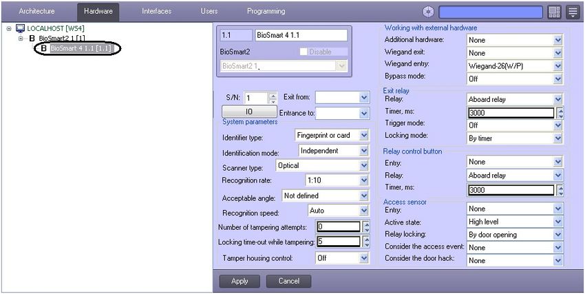
Walk-through parameters of BioSmart 4 controller are configured on the settings panel of the BioSmart 4 object:
1. In the Exit from dropdown list select the Region object corresponding to the territory situated on the side of entrance to
the territory via the controller (1).
2. In the Entrance to dropdown list select the Region object corresponding to the territory situated on the side of exit from
the territory via the controller (2).
3. Select the walk-through mode in the Identifier type dropdown list (3).
Walk-through modes are presented in the following table.
Walk-through mode Description
Fingerprint or card Access is guaranteed when scanning a fingerprint or access card
Configuring BioSmart integration module – 9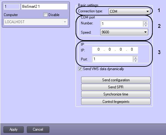
BioSmart Integration Module Configuration and Operation Manual

        Walk-through mode                                       Description

        Fingerprint+card                                        Access is guaranteed when placing an access card and then scanning a fingerprint for 10
                                                                seconds

        Code+fingerprint                                        Access is guaranteed when entering the access code onto the dial pad (if it is enabled) and
                                                                then scanning a fingerprint for 10 seconds

        Fingerprint on card                                     Access is guaranteed after matching fingerprint template on the Mifare card with user
                                                                fingerprint scanned for 10 seconds after placing the Mifare card.

   4. Select the controller's operation mode in the Identification mode dropdown list (4). When the off-line mode is enabled,
      then controller is responsible for providing access, when the server mode is enabled – Server of ACFA Intellect is
      responsible for providing access.
   5. In the corresponding list select the type of scanner used in the reader (5).

               Attention!
               Only recommended values specified in steps 6-8 are to be set. Other values are to be approved by BioSmart ACS
               vendor. For the values to take effect the configuration is to be sent to controller (see Sending configuration to
               controller section).

   6. In the Recognition rate list select the rate of false identification by a fingerprint (6). Recommended value – 1/100000.
   7. Select the maximum acceptable angle of fingerprint rotation about boresight (in degrees) (7). Recommended value – 30.
   8. Select the fingerprint recognition algorithm in the Recognition speed list (8). The faster recognition speed, the more
      likely the false access denial. The Auto value is to be in use – in this mode the speed is determined automatically
      depending on the number of fingerprint templates in the controller database.
   9. In the Number of tampering attempts field specify the number of failed access attempts by any identifier – if the
      specified number of failed access attempts is exceeded, then the controller will be locked out for Locking time-out while
      tampering (see step 10, 9).
  10. In the Locking time-out while tampering field specify the time (in seconds) of locking controller when the number of
      failed access attempts is exceeded (10).
  11. To enable tamper housing control set the On value for the corresponding parameter (11). In this case when the controller
      housing is tampered, the corresponding event and alarm occur.
  12. Click the Apply button to save all changes.
Walk-through parameters of BioSmart 4 controller are now configured.

4.3.2 Configuring BioSmart 4 controller working with external hardware
BioSmart 4 controller working with external hardware is configured on the settings panel of the BioSmart 4 object:
   1. In the Additional hardware list select the type of device connected to the port of controller 2 (1).

       List of additional hardware is presented in the following table.
        Additional hardware           Description

        None                          Additional hardware is not connected

        BioSmart relay control unit   BioSmart relay control unit is connected to the controller

                                                                                                        Configuring BioSmart integration module – 10
BioSmart Integration Module Configuration and Operation Manual
SK-24 Key storage device is connected to the controller
Kronwerk Controller works in the Kronwerk integration mode under control of Kronwerk software
BioSmart BOX BioSmart BOX is connected to the controller
Perco Controller works in the Perco integration mode under control of Perco software
2. In the Wiegand exit list select the protocol type of Wiegand output of BioSmart 4 controller (2).
Protocol type of Wiegand output of BioSmart 4 controller is presented in the following table.
Additional hardware Description
None No third-party controller is connected to Wiegand output of BioSmart 4 controller
Wiegand 26 Third-party controller that uses Wiegand 26 protocol is connected to Wiegand output of BioSmart 4 controller
Wiegand 32 Third-party controller that uses Wiegand 32 protocol is connected to Wiegand output of BioSmart 4 controller
3. In the Wiegand entry list select the protocol type of Wiegand input of BioSmart 4 controller (3).
4. To enable the bypass mode set the On value for the corresponding parameter (4). In this case the card that is not
registered in the database of ACFA Intellect can be transferred to the third-party controller via Wiegand output of
BioSmart 4 controller.
5. Click the Apply button to save all changes.
BioSmart 4 controller working with external hardware is now configured.
4.3.3 Configuring relay of BioSmart 4 controller
Relay of BioSmart 4 controller is configured on the settings panel of the BioSmart 4 object:
1. Configure the exit relay of BioSmart 4 controller in the corresponding parameter group:
a. In the Relay list select the type of relay that will be triggered when walking through (1).
b. In the Timer field specify time (in milliseconds) of active state of the relay after its triggering (2).
c. To enable the trigger mode set the On value for the corresponding parameter (3). In this case the relay will change
its state after each success access. When the controller is switched on after its power failure, the relay returns to
the state it had when power was switched off.
d. In the corresponding list select the relay locking mode (4).
Manual mode – locking is activated when the Open button is pushed and inactivated when the Close button is
pushed.
By timer – locking is activated when the Open button is pushed and inactivated in time period specified in the
Timer field (see step 1.2).
2. Configure the relay control button in the corresponding group of parameters:
Configuring BioSmart integration module – 11BioSmart Integration Module Configuration and Operation Manual
a. In the corresponding list select the entry to which the button is connected (5).
If the button is disabled, then set the None value. In this case, skip the following steps.
b. Select the type of relay that triggers when pushing the control button (6).
c. In the Timer field specify time (in milliseconds) of active state of the relay after pushing the relay control button
(7).
3. Click the Apply button to save all changes.
Relay of BioSmart 4 controller is now configured.
4.3.4 Configuring access sensor of BioSmart 4 controller
Access sensor of BioSmart 4 controller is configured on the settings panel of the BioSmart 4 object:
1. Select the entry to which the access sensor is connected (1). If the access sensor is not connected, then set the None
value. In this case, skip the following steps.
2. In the Active state list select the level of signal at discrete input at which the sensor triggering is detected (2).
3. In the corresponding list select the relay locking mode when the access sensor is triggered (3). By door opening – relay is
disabled at rising edge of access sensor triggering. By door closing - relay is disabled at falling edge of access sensor
triggering.
4. If the access event is to be taken into consideration, then select the Yes value in the corresponding list (4).
5. If the door hack is to be taken into consideration, then select the Yes value in the corresponding list (5).
6. Click the Apply button to save all changes.
Access sensor of BioSmart 4 controller is now configured.
4.3.5 Configuring operating scenarios for executive devices of BioSmart 4 controller
It is possible to configure triggering of executive devices of BioSmart 4 controller when events appear in the system. For this do
the following:
1. Click the IO button on the settings panel of the BioSmart 4 object.
Configuring BioSmart integration module – 12BioSmart Integration Module Configuration and Operation Manual
2. In the IO parameters list select the executive device the reaction is to be set to (1).
3. Use the >> button in order to forward events that trigger the executive device from the Forbidden events list to the
Allowed events list (2).
4. In the Delay field specify time (in milliseconds) that is to pass after receiving the selected event until the executive device
becomes active (3).
5. In the Repetitions field specify the number of the executive device triggerings after receiving the selected event (4).
6. In the Active state delay field specify time (in milliseconds) for which the executive device is to become active (5).
7. In the Inactive state delay (ms) field specify time (in milliseconds) between triggerings of executive device when there
are repetitions (6).
8. Repeat steps 2-7 for all required types of executive devices.
9. Click the Save and then the Apply button.
Operating scenarios for executive devices of BioSmart 4 controller are now configured.
4.4 Configuring BioSmart PROX v.2 and BioSmart PROX-E controllers
BioSmart Prox v.2 and BioSmart Prox-E controllers are configured the same way on the settings panel of the BioSmart PROX
object (see Configuring connection of BioSmart ACS controllers section).
4.4.1 Configuring access parameters
Access parameters are configured as follows:
1. Select the controller operation mode in the Identification mode dropdown list (1). When the off-line mode is enabled,
then controller is responsible for providing access, when the server mode is enabled – Server of ACFA Intellect is
responsible for providing access.
2. To enable tamper housing control set the On value for the corresponding parameter (2). In this case when the controller
housing is tampered, the corresponding event and alarm occur.
Configuring BioSmart integration module – 13BioSmart Integration Module Configuration and Operation Manual
3. In the Number of tampering attempts field specify the number of failed access attempts by any identifier – if the
specified number of failed access attempts is exceeded, then the controller will be locked out for Locking timer while
tampering (see step 4, 3).
4. In the Locking timer while tampering field specify the time (in seconds) of locking controller when the number of failed
access attempts is exceeded (4).
5. Click the Apply button to save all changes.
Access parameters are now configured.
4.4.2 Configuring operation mode of controller
BioSmart Prox v.2 and BioSmart Prox-E controllers support 3 operation modes.
Note.
The Escort operation mode is currently not supported by ACFA Intellect.
Operation modes of BioSmart PROX v.2 and BioSmart PROX-E controllers are presented in the following table.
Operation mode Description
Standard Access is guaranteed when scanning a fingerprint or access card
Multi-access Access is guaranteed when scanning fingerprints (placing access card) on different sides of the door
Gateway Access is guaranteed to the walk-through premises, the second door can't be opened before the first door is closed
Operation mode is configured as follows:
1. Select the controller's operation mode in the Access mode dropdown list (1).
2. If the Multi-access mode is selected, then in the Waiting time field specify maximum possible time (in milliseconds)
between scanning fingerprints (placing access cards) on different sides of the door (2). If this time-limit is exceeded, then
access is denied.
3. If the Gateway mode is selected, then match sensors and access points with discrete inputs (3).
4. Click the Apply button to save all changes.
Operation mode is now configured.
4.4.3 Configuring discrete and alarm inputs of controller
To configure discrete and alarm inputs of controller, do the following:
Configuring BioSmart integration module – 14BioSmart Integration Module Configuration and Operation Manual
1. Click the Entry parameters on the settings panel of the BioSmart PROX object.
2. Set the following parameters for each discrete input:
a. In the Active level list select the level of signal at discrete input at which the access sensor triggering is detected
(1).
b. In the corresponding list select the relay of controller that is event-triggered on the discrete input (2).
c. In the Eventlist select the type of event processed by controller when the signal of specified level arrives to
discrete input (3).
Types of event processed by controller are presented in the following table.
Event type Description
Not assigned Signals from corresponding discrete input are not processed
Relay control button Signal of specified level caused by pushing the button is processed
Access sensor Signal of specified level caused by walking through the turnstile or the door is processed
Unlocking sensor Signal of specified level caused by unlocking the relay is processed
d. In the Timer field specify time (in milliseconds) of active state of the relay after its triggering (4).
3. Specify the following parameters for each alarm input:
a. In the Active level list select the level of signal occurring at alarm input – it triggers access sensor (5).
b. In the Event list select the type of sensor which triggering causes controller action (door locking, door unlocking,
fire alarm activation, 6).
4. Click the OK and then the Apply button.
Discrete and alarm inputs of controller are now configured.
4.5 Configuring BioSmart-mini reader
BioSmart-mini reader is configured on the settings panel of the BioSmart-mini reader object. This object is created on the base
of the BioSmart PROX object.
BioSmart-mini reader is configured as follows:
Configuring BioSmart integration module – 15BioSmart Integration Module Configuration and Operation Manual
1. In the Address field specify the address of the reader in the BioSmart ACS internal network (1).
2. In the Identifier type dropdown list select the mode of access via the reader (2).
Fingerprint or card – access will be guaranteed after scanning a fingerprint or access card.
Fingerprint and card – access will be guaranteed after placing an access card and then scanning a fingerprint for 10
seconds.
3. In the corresponding list select the type of scanner used in the reader (3).
Attention!
Only recommended values specified in steps 4-6 are to be set. Other values are to be approved by BioSmart ACS
vendor. For the values to take effect the configuration is to be sent to controller (see Sending configuration to
controller section).
4. In the Recognition rate list select the rate of false identification by a fingerprint (4). Recommended value – 1/100000.
5. Select the maximum acceptable angle of fingerprint rotation about boresight (in degrees) (5). Recommended value – 30.
6. Select the fingerprint recognition algorithm in the Recognition speed list (6). The faster recognition speed, the more
likely the false access denial. The Auto value is to be in use – in this mode the speed is determined automatically
depending on the number of fingerprint templates in the controller database.
7. Select the type of access cards the reader uses (7).
8. Select the access direction in the corresponding list (8).
9. Disable relay while door opening/closing if necessary (9).
10. If the trigger mode is to be enabled for relay (relay changes its state after each success access), then set the Yes value in
the corresponding list (10).
11. In the Access sensor list select the discrete input of controller with the events of which the reader will work (11).
12. If necessary let pass by RFID access card with any code (12).
Note.
This parameter is relevant only if the reader with RFID access cards is in use (see step 7).
13. In the Exit from dropdown list select the Region object corresponding to the territory situated on the side of entrance to
the territory via the reader (13).
14. In the Entrance to dropdown list select the Region object corresponding to the territory situated on the side of exit from
the territory via the reader (4).
Configuring BioSmart integration module – 16BioSmart Integration Module Configuration and Operation Manual
Click the Apply button to save all changes.
4.6 Configuring BioSmart reader (all models)
BioSmart reader is configured on the settings panel of the BioSmart reader object. This object is created on the base of the
BioSmart PROX object.
Settings parameters of BioSmart Prox controller are the same as corresponding settings of BioSmart-mini reader (see
Configuring BioSmart-mini reader section).
4.7 Sending configuration to controller
Configuration is sent to a controller on the settings panel of the BioSmart2 object.
To send configuration to the controller click the Send configuration button (1).
Note
When you click the Send configuration button, only the hardware settings are written to controller.
To send the Server time to controller, click the Synchronize time button.
For information on writing the VMS data to controller, please refer to the Writing the VMS data to controller section.
4.8 Writing the VMS data to controller
The Visitor Management System data, such as users, cards and fingerprints, is written to controller using the BioSmart2 object
settings panel.
To write the VMS data to the controller, click the Send SPR (1) button.
If the VMS data is to be sent to the controller dynamically, set the Send VMS data dynamically checkbox (2) and click
the Apply button to save the changes.
Note
When you click Send SPR, the controller is initialized, and all the existing VMS data is deleted and then replaced with
up-to-date records.
Configuring BioSmart integration module – 17BioSmart Integration Module Configuration and Operation Manual
Note
When the VMS data is written to controller, the system sends out only the information about users with an access level
in Access Manager that allows passing through the given access point. For more information about access levels, see
Access Manager Module Settings and Operation Guide.
Note
When the VMS data is written to controller, the System Information event in Event Manager is generated that indicates
the number of users being recorded or blocked, and whether the users are recorded successfully. For more information
about system events, see Event Manager Module Settings and Operation Guide.
4.9 Managing the BioSmart fingerprints
To add fingerprints, do the following:
1. On the settings panel of the BioSmart2 object, click the Control fingerprints button.
Configuring BioSmart integration module – 18BioSmart Integration Module Configuration and Operation Manual
2. Find a user by the ID or surname by clicking the Find button (1).
3. Select the user (2) and click the Add fingerprint button (3).
4. Select an available fingerprint reader and click the Select reader button (1-2).
Configuring BioSmart integration module – 19BioSmart Integration Module Configuration and Operation Manual
5. A dialog box showing fingerprint reading status opens.
6. Put a finger on the reader and hold it until you hear a beep. When reading of the fingerprint is finished, a number of
fingerprints read is displayed in the Fingerprint reading dialog box. A dialog box instructing to put the finger to the
reader again opens.
7. Put the same finger on the reader and hold it until you hear a beep. Click Yes in the opened dialog box to save fingerprints
or No to cancel input.
Note.
Two copies of the same fingerprint, i.e. a comparison pair, are read per one cycle (steps 6-7). A Biosmart
controller allows 5 comparison pairs per user.
8. The number of fingerprints added for the selected user will be displayed in the Control fingerprints box.
9. Add fingerprints for all required users.
Configuring BioSmart integration module – 20BioSmart Integration Module Configuration and Operation Manual
Note.
To delete fingerprints, select the user in the box and click the Delete fingerprints button.
10. Write the VMS data to controller (see Writing the VMS data to controller section). If the Send VMS data dynamically
checkbox is set checked, then there is no need to perform this action.
Attention!
For correct user identification it is required to fill the Object code and the Card fields in the Visitor Management System
interface module (see the Adding user access cards using a reader section).
Fingerprints are now added to the system.
Configuring BioSmart integration module – 21BioSmart Integration Module Configuration and Operation Manual
5 Working with BioSmart integration module
5.1 General information about how to work with BioSmart integration module
The following interface objects are in use when working with BioSmart module:
1. Card;
2. Event Viewer.
Information on how to configure these interface objects can be found in Intellect Software package: Administrator's Guide.
Information on how to work with these interface objects can be found in Intellect Software package: Operator's Guide.
5.2 Managing BioSmart controllers
Any BioSmart controller is managed in the Card interactive dialog box using the feature menu of the corresponding object
(BioSmart 4 or BioSmart PROX).
Description of feature menu of the BioSmart object is given in the table.
Menu command Functionality
Close Door is closed
Open Door is opened
Working with BioSmart integration module – 22You can also read