CX EMS ENERGY MANAGEMENT SYSTEM - THE GLOBAL SPECIALIST IN ELECTRICAL AND DIGITAL BUILDING INFRASTRUCTURE - Legrand
←
→
Page content transcription
If your browser does not render page correctly, please read the page content below

CX³ EMS
                  ENERGY MANAGEMENT SYSTEM
 GUIDE
TECHNICAL

THE GLOBAL SPECIALIST IN ELECTRICAL AND
DIGITAL BUILDING INFRASTRUCTURE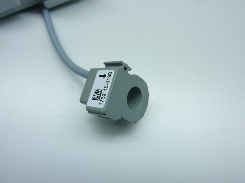
Legrand offers complete solutions to meet energy efficiency
                                              needs.

                                              This technical guide provides all the essential information
                                              you need to know about CX3 EMS in order to understand
                                              how to choose them, their characteristics, installation and
                                              configuration rules, etc …

                                              This document can be downloaded from the online catalog
                                              and is a complete technical guide on CX3 EMS in the
                                              distribution board.

        LEGAL INFORMATION
Particular attention must be paid on pre-
sentation pictures that do not include
personal protective equipment (PPE).
PPE are legal and regulatory obligations.
In accordance with its continuous impro-
vement policy, Legrand reserves the right
to change the specifications and illus-
trations without notice. All illustrations,
descriptions and technical information
included in this document are provided
as indications and cannot be held against
Legrand.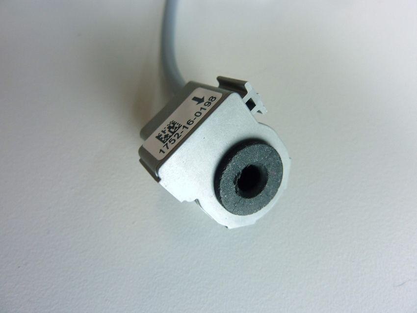
TABLE OF CONTENTS
                  CX³ EMS MEASUREMENT MODULES. . . . . . . . . . . . . . . . . . . . . . . . . . 6

                  CX³ EMS PULSE CONCENTRATOR. . . . . . . . . . . . . . . . . . . . . . . . . . . . 20

                  CX³ EMS UNIVERSAL SIGNALLING MODULE. . . . . . . . . . . . . . . . . . . 24

                  CX³ EMS AC + FC SIGNALLING AUXILIARY MODULE. . . . . . . . . . . . . 32

                  CX³ EMS UNIVERSAL CONTROL MODULE . . . . . . . . . . . . . . . . . . . . . 38

                  CX³ EMS CONTROL AND STATE REPORTING MODULE. . . . . . . . . . 46

                  CX³ EMS POWER SUPPLY MODULE. . . . . . . . . . . . . . . . . . . . . . . . . . . 54

                  CX³ EMS ACCESSORIES AND CONNECTIONS . . . . . . . . . . . . . . . . . . 58

                  CX³ EMS / RS485 INTERFACE. . . . . . . . . . . . . . . . . . . . . . . . . . . . . . . . 64

                  CX³ EMS MINI-CONFIGURATOR. . . . . . . . . . . . . . . . . . . . . . . . . . . . . . 68

                  CX³ EMS CONFIGURATION SOFTWARE. . . . . . . . . . . . . . . . . . . . . . . . 74

                                                        CX³ EMS Energy Management System                   TECHNICAL GUIDE   3
WWW.LEGRAND.COM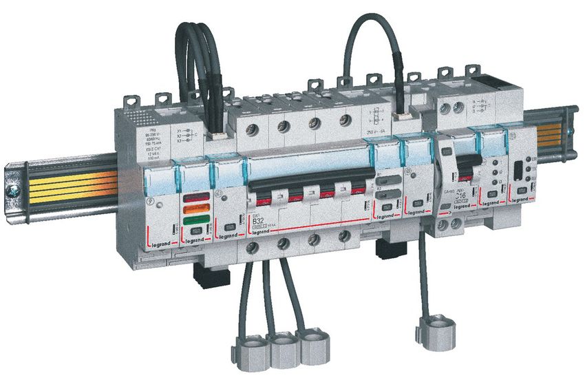
CXcomplete,
                      3
                       EMS
                              compact
                     and multifunctional

                      MEASUREMENT          SIGNALLING

              S
            NT
          TE
        ON
      FC
    EO
 ABL
T

             4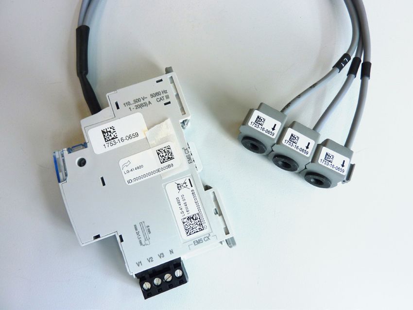
All the modules in the CX3 EMS supervision system
                       have compact dimensions, in order to minimise the
                               space taken up in the electrical switchboard.

 CONTROL          SIGNALLING &     COMMUNICATION                   PROGRAMMING
                    CONTROL                                         AND DISPLAY

                                                                                                          S
                                                                                                        NT
                                                                                                      TE
                                                                                                    ON
                                                                                                  FC
                                                                                                EO
                                                                                             ABL
                                                                                            T

                                       CX³ EMS Energy Management System   TECHNICAL GUIDE   5
WWW.LEGRAND.COM
CX³ EMS
                                                MEASUREMENT MODULES

                  Product specifications
                  Measurement modules are integrated in the EMS CX³ system for monitoring energy in electrical panels.
                  Offering the same performance as conventional measurement control units, these record the electricity consumed by a single-phase
                  or three-phase circuit and measure the electrical values (current, voltage, power, frequency, harmonics, etc).
                  There are 2 measurement module families:
                  ■ measurement up to 125 A with closed Rogowski coils
                  ■ high-current measurement with open Rogowski coild or with CT.

              S
            NT
          TE
        ON
      FC
    EO
 ABL
T

             6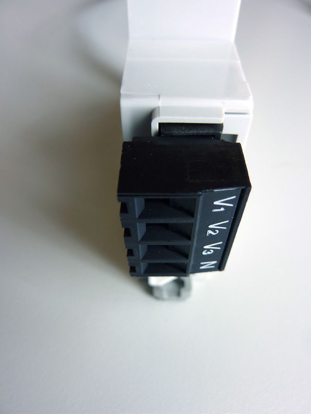
CHARACTERISTICS
■ Display:                                   ■ Supply voltage:                          ■ Connection with CT:
    No display on the module itself, however       12 VDC via CX3 EMS power supply              Supplied for Cat.Nos 4 149 18 / 19 / 20 /
    data can be displayed locally (on mini-        module Cat.No: 4 149 45.                     21 / 22 / 24 / 25 / 27.
    configurator Cat.No 4 149 36/37), or                                                        Not supplied for Cat.No 4 419 23.
                                               ■ Frequency: 50 – 60 Hz
    remotely (on a PC, tablet or smartphone
                                                                                            ■ Output:
    screen).                                   ■ Conforming to standards:
                                                                                                Via communication rail or cable on the
                                                 IEC / EN 61557-12
■ Rated voltage Un:                                                                           EMS CX³ bus. Modbus RS485 output option
                                                 IEC/EN 61131-2
 Single-phase: 65 to 290 VAC                                                                    via interface Cat.No 4 149 40.
                                                 (PLC)
 Three-phase: 110 to 500 VAC
                                                                                            ■ Mounting: on DIN rail.
                                               ■ Accuracy:
■ Consumption:
                                                   Active energy                            ■ Dimensions: width 1 module.
    4 149 19: 34,1 mA - 0,410 W
                                                   (IEC / EN 61557-12): class 0.5
  4 149 20: 34,8 mA - 0,419 W
                                                   Reactive energy
  4 149 23: 32,6 mA - 0,391 W
                                                   (IEC / EN 61557-12): class 1
  4 149 18: 34.8mA – 0.418 W
  4 149 21: 34.8mA – 0.418 W
  4 149 22: 34.8mA – 0.418 W
  4 149 24: 34.8mA – 0.418 W
  4 149 25: 34.8mA – 0.418 W

                                                                                                                                                          S
                                                                                                                                                        NT
                                                                                                                                                      TE
                                                                                                                                                    ON
                                                                                                                                                  FC
                                                                                                                                                EO
                                                                                                                                             ABL
                                                                                                                                            T

                                                                           CX³ EMS Energy Management System      TECHNICAL GUIDE        7
       WWW.LEGRAND.COM
PRODUCT SELECTION
                  The measurement module should be chosen according to the supply (single-phase or three phase), its maximum current and,from
                  the current transformer type.

                                                                        4 149 18           4 149 19           4 149 20           4 149 21

                  Supply type      Single-phase                             /                 OK                  /                  /
                                   Three-phase                             OK                  /                 OK                 OK
                  Number of modules                                         1                  1                  1                  1
                                   Direct (max.current)                Up to 63 A         Up to 63 A         Up to 63 A         Up to 125 A
                  Connection
                                   Via a current transformer                /                  /                  /                  /
                                   Total active energy                     OK                 OK                 OK                 OK
                                   Total reactive energy                   OK                 OK                 OK                 OK
                                   Partial active energy (reset)           OK                 OK                 OK                 OK
                                   Partial reactive energy (reset)         OK                 OK                 OK                 OK
                                   Active power                            OK                 OK                 OK                 OK
                                   Reactive power                          OK                 OK                 OK                 OK
                                   Apparent power                          OK                 OK                 OK                 OK
                  Metering and
                  measurement      Current + voltage                       OK                 OK                 OK                 OK
                                   Frequency                               OK                 OK                 OK                 OK
                                   Power factor                            OK                 OK                 OK                 OK
                                   THD phase-to-neutral voltages           OK                 OK                 OK                 OK
                                   THD phase-to-phase voltages             OK                 OK                 OK                 OK
                                   THD currents                            OK                 OK                 OK
                                   THD Odd-order harmonics           Up to 15th order   Up to 15th order   Up to 15th order   Up to 15th order
                  Communication    CX³ EMS protocol                        OK                 OK                 OK                 OK
                                   Load shedding according to a
                  Load shedding    measurement threshold that has          OK                 OK                 OK                 OK
                                   been reached

              S
            NT
          TE
        ON
      FC
    EO
 ABL
T

             8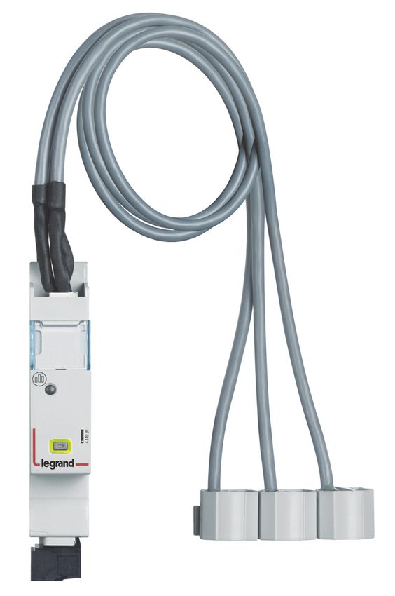
4 149 22           4 149 24           4 149 25                   4 149 27                   4 149 23

       /                  /                  /                          /                         OK
      OK                 OK                 OK                         OK                         OK
       1                  1                  1                          1                          1
  Up to 630 A       Up to 1600 A       Up to 3200 A                Up to 6300 A                    /
       /                  /                  /                          /              5 A at the secondary
      OK                 OK                 OK                         OK                         OK
      OK                 OK                 OK                         OK                         OK
      OK                 OK                 OK                         OK                         OK
      OK                 OK                 OK                         OK                         OK
      OK                 OK                 OK                         OK                         OK
      OK                 OK                 OK                         OK                         OK
      OK                 OK                 OK                         OK                         OK
      OK                 OK                 OK                         OK                         OK
      OK                 OK                 OK                         OK                         OK
      OK                 OK                 OK                         OK                         OK
      OK                 OK                 OK                         OK                         OK
      OK                 OK                 OK                         OK                         OK
      OK                 OK                 OK                         OK                         OK
Up to 15th order   Up to 15th order   Up to 15th order           Up to 15th order           Up to 15th order
      OK                 OK                 OK                         OK                         OK

      OK                 OK                 OK                         OK                         OK

                                                                                                                                S
                                                                                                                              NT
                                                                                                                            TE
                                                                                                                          ON
                                                                                                                        FC
                                                                                                                      EO
                                                                                                                   ABL
                                                                                                                  T

                                                         CX³ EMS Energy Management System       TECHNICAL GUIDE   9
WWW.LEGRAND.COM
VIEWING DATA
                  To minimise the dimensions, measurement modules do not have a data display. Nonetheless various display modes are possible:
                  Locally, int the enclosure, on mini-configurator,                Remotely, on a PC, tablet or smartphone screen. The CX³ EMS /
                  Cat.No 4 149 36 :                                                RS485 / IP interfaces Cat.No 4 149 40 and 0 046 89 must be used to
                                                                                   access devices such as the touch screen, the Energy Management
                                                                                   software Cat.No 4 149 38/39 and the Energy Web Server
                                                                                   Cat.No 4 149 47/48/49.

              S
            NT
          TE
        ON
      FC
    EO
 ABL
T

           10
Câble 1 x 0,5 mm² to 2,5 mm² 2 x 1,5
-
rigide mm²
Câble 1 x 0,5 mm² to2,5 mm² 2 x 1,5 1 x 0,5 mm² to 2,5 mm² 2 x 1,5
souple mm² mm²
. Current rogowski coil(s)
AVEC le support SANS le support
plastique interne F: 0,5 A gG
plastique interne
En triphasé avec 4 câbles et 3 transformateurs (3N-3E):
Câble 1 x 1,5 mm² to 16 mm² ø 4,8 1 x 1,5 mm² to 25 mm² ø 9,3
rigide mm mm
WIRING
Câble 1 x 1,5 mm² to 10 mm² ø 4,8 1 x 1,5 mm² to 16 mm² ø 9,3 F: to
0,5the
A gG
Measurement modules have 2 types of input: “current” and “voltage” inputs. Each current transformer secondary is connected
souple mm mm
corresponding inputs and thus allows the current flowing through the CT.La to longueur
be measured. Toentre
du câble measure
le/lesthe voltage,
tore(s) each (cf
Rogowski conductor
§ Côtes is
connected to the respective voltage tap terminals. d’encombrement) laisse la possibilité de mettre le module de
Schéma de câblage :
■ Current measurement for measurement modules to be connected bymesure closed sur n’importe
Rogowski coil qu’elle
up torangée,
125 A: dans la limite de cette
Note: longueur. De ce fait, il est possible de positionner le module de
3 measurement modules are available for Each coil is supplied with a flexible internal
. Les tores peuvent être positionnés indifféremment en amont ou mesure sur une rangée différente de l’appareil qu’il mesure.
measurement up to 63 A and 1 Cat.No up guide which ensures the cable is centered
en aval de l’appareil qu’il mesure.
to 125 A. in the coil. Depending on the cable cross-
They are supplied with closed Rogowski section, the guide can be removed or
coil(s) for single-phase or three-phase retained.
measurement.
Cat. No 4 149 18 for 3 single-phase
measurement:
The coil(s) on a measurement
module can be disconnected. The
coils are calibrated in the factory
for use in conjunction with the measure-
. Les tores doivent être positionnés dans le sens du courant (une ment modules.
flèche est dessinée sur le tore) If several modules are used in the same
Cependant la direction du courant peut être changée si nécessaire installation, it is important to check,
via le Software de configuration ou le Mini Configurateur before mounting, that the serial number
modulaire EMS CX3 (réf. 4 149 36/37). are identical on the coil and module
Cat.No
.44 149
149 1919 for a single identification labels.
phase measurement:
. En monophasé (1N-1E): The coils can be separated for better
integration in existing installations.
The coils are marked L1 . L2 . L3. Wiring
Référence(s) : 4 149 19/20
Référence(s) : 4 149 19/20 must be done in this order, for the data to
be displayed correctly.
4. MISE EN SITUATION - RACCORDEMENT (suite)
4. MISE EN SITUATION - RACCORDEMENT (suite)
F: 0,5 A gG
Schéma de câblage (suite) :
Schéma de câblage (suite) :
Cat.No
. 4 149 204 149 20 (63 A) / 4 149 21 (125
. 4 149 20
A)EnforFiche
a technique
3 câbles:measurement:
three-phase
triphasé avec F02335FR/01
et 3 transformateurs (3-3E): Mise à jour le : - Créée le : 21/10/2016
ut En triphasé avec 3 câbles et 3 transformateurs (3-3E):
ut
3 / 17
m² 2 x 1,5
m² 2 x 1,5
port
port F: 0,5 A gG
erne F: 0,5 A gG
erne
En triphasé avec 4 câbles et 3 transformateurs (3N-3E):
En triphasé avec 4 câbles et 3 transformateurs (3N-3E):
S
NT
TE
m² ø 9,3 EO
FC
ON
m² ø 9,3 TABL
m² ø 9,3 F: 0,5 A gG CX³ EMS Energy Management System TECHNICAL GUIDE 11
m² ø 9,3 F: 0,5 A gG
WWW.LEGRAND.COM
.La longueur du câble entre le/les tore(s) Rogowski (cf § Côtes
.La longueur du câble entre le/les tore(s) Rogowski (cf § Côtes
d’encombrement) laisse la possibilité de mettre le module de
d’encombrement) laisse la possibilité de mettre le module deWIRING (CONTINUED)
■ 63 A 3 x Single: ■ 63 A Three:
Cat.No 4 149 18 Cat.No 4 149 20
■ 63 A 3 x Single: ■ 125 A Three:
Cat.No 4 149 19 Cat.No 4 149 21
S
NT
TE
ON
FC
EO
ABL
T
12Référence(s) : 4 149 23
Référence(s) :: 44 149
Référence(s) 149 23
23
4. MISE EN SITUATION - RACCORDEMENT (suite)
Type de conducteur :
ation spécifique 4.
4. MISE EN.SITUATION
MISE EN Pour les --bornes
SITUATION amont(suite)
RACCORDEMENT
RACCORDEMENT :
(suite)
Type de
de conducteur
conducteur :: Câble cuivre
Type
pécifique
)pécifique
pour une .. Pour
Pour les
les bornes
bornes amont
amont :: Sans embout Sans embout
Câble cuivre
Câble cuivre
Câble 1 x 0,5 mm² to 2,5 mm² 2 x 1,5
une Sans embout
Sans embout Sans embout
Sans embout -
une rigide mm²
Câble
Câble 11 xx 0,5
0,5 mm²
mm² to
to 2,5
2,5 mm²
mm² 22 xx 1,5
1,5
rigide Câble 1 x 0,5 mm² to 2,5 mm² 2 x 1,5
mm² -- 1 x 0,5 mm² to 2,5 mm² 2 x 1,5
rigide mm²
souple mm² mm²
Câble
Câble 11 xx 0,5
0,5 mm²
mm² to
to 2,5
2,5 mm²
mm² 22 xx 1,5
1,5 11 xx 0,5
0,5 mm²
mm² to
to 2,5
2,5 mm²
mm² 22 xx 1,5
1,5
souple EMS CX3 – Centrale de mesure pour Référence(s) : 4
souple. Pour le bloc mm² aval amovible noir (câblage
mm² mm²de la tension):
mm²
.. Pour
Pour le
le bloc
bloc aval
aval amovible
amovible noir
noir (câblage
(câblage de laCâble
de la cuivre
tension):
tension):
transformateurs de courants (TI)
Sans Câble cuivre
embout
Câble cuivre Sans embout
4. MISE EN SITUATION - RACCORDEMENT (suite) 4. MISE EN SITUA
WIRING (CONTINUED)
Sans embout Sans embout
Câble Sans embout Sans embout
1 x 0,5 mm² to 2,5 mm² 2 x 1,5
Schéma de câblage (suite) : Transmission des
■ Current measurement
rigide
11 xx 0,5
0,5 mm²
for
mm² to
to 2,5
measurement
2,5 mm²
mm² 22 xx 1,5
1,5
modules to be connected
- by current transformer for high current measurement:
Câble
Câble mm² . Pour les bornes amont :
ur une connexion -- . Par rails com
rigide
One measurement
rigide module
mm² is available for high current
e connexion
connexion mm²
1 x 0,5 mm² to2,5 mm² 2 x 1,5 1 x 0,5 mm² to 2,5 mm² 2 x 1,5 HIGH CURRENT MEASUREMENT
e measurement. ItCâble
is supplied without a CT and can be wired to any
1 xx 0,5
Câble souple
1 0,5 mm²
mm² to2,5
to2,5 mm²
mm² 22 xx 1,5
1,5 1 xx 0,5
1 0,5 mm²
mm² to
to 2,5
2,5 mm²
mm² 22 xx 1,5
1,5
Câble
type of ferromagnetic coil, open or closed, 5 A at the secondary.
mm² mm²
souple
souple mm² mm²
mm² mm²
This measurement
Schémamodule
de câblageCat.No
: . En 4 149 23 provides the option of
Schémaade
measuring
Schéma câblage :: .. En
desingle-phase
câblage En or three- phase supply. Permettent la
monophasé (1N-1E):
monophasé (1N-1E):
monophasé (1N-1E): modules EMS
Ce type de con
modules EMS
Configuration du module :
. Pour cette centrale les configurations suivantes sont
F: 0,5
F: 0,5 A
A gG
gG
F: 0,5 A gG possibles :
.. En
En triphasé
triphasé avec
avec 3
3 câbles
câbles et
et 3 transformateurs (3-3E):
(3-3E): ■ Current measurement for measurement modules
. En triphasé avec 33 transformateurs
câbles et 3 transformateurs (3-3E): Sens du courant
to be connected by open Rogowski coils:
Type d’insertion (avec ou sans le neutre) [Cf § schéma de
câblage] Mise en œuvre : da
4 Modules dedicated to EMS CX3 (Energy Management System)
Ces configurations sont possible via le software de configuration l’arrière de tou
NI7596 type
type Multifunction measurement modules for high currents that allow transmission d
NI7596 EMS CX3 (téléchargeable gratuitement) ou avec le Mini
°1 (UNI7596 type to measure the main electrical data of a three-phase circuit.
Configurateur modulaire EMS CX3 (réfs. 4 149 36/37)
:: vis
vis fendues
fendues ■ Measurement via open, felxible Rogowski coils:
nsion): vis fendues Transmission des données EMS CX3 (connexion des modules) :
.Par cordons communicants (réfs.4 149 07/08/09)
V33,)
V ,) :: 0,5
0,5 Nm.
Nm. F: 0,5
0,5 A
A gG
gG
F:
V1, V2, V3,) : 0,5 Nm. .. En
En triphasé
triphasé avec
avec 4
4 câbles
câbles et
et 3
3 transformateurs
transformateurs (3N-3E):
(3N-3E): F: 0,5 A gG
me de
me de 4
4 3N-3E
. En triphasé avec 4 câbles et 3 transformateurs (3N-3E):
Permettent la transmission des données entre les différents
ou à lame de 4
: tournevis
: tournevis modules EMS CX3.
Ce type de connexion est recommandé lorsqu’il y a peu de modules
aximum).
nsion) : tournevis
aximum). EMS CX3 sur une rangée ou dans une enveloppe.
mm maximum).
F: 0,5
F: 0,5 A
A gG
gG
How to determine the maximum possible length between 3-3E
the CTs and the measurement module is explainedF:in0,5the
A gG
Mise en œuvre : avec cette façon de câbler, le cache plastique
“Current transformers”
Mise à jour le : 07/11/2016 technical guide.
Créée le : 21/10/2016
Mise à jour le : 07/11/2016 Créée le : 21/10/2016 présent à l’arrière de tous les modules EMS CX3 ne doit pas être
enlevé.
2 // 16
2 16
Mise à jour le : 07/11/2016 Créée le : 21/10/2016
2 / 16
S
NT
TE
ON
FC
EO
ABL
T
CX³ EMS Energy Management System TECHNICAL GUIDE 13
WWW.LEGRAND.COMWIRING (CONTINUED)
■ 630 A, 1600 A, 3200 A et 6300 A:
Cat.No 4 149 22 Cat.No 4 149 24 Cat.No 4 149 25 Cat.No 4 149 27
Measure with open flexible Rogowski coils. High performance: measurement modules: up to 6300 A. The range of CX3 EMS
measurement modules, now allows to measure high currents 630 A, 1600 A, 3200 A and 6300 A.
Open flexible coils:
Adjust the busbars perfectly in all positions (horizontal, vertical). Ultra compact Rogowski. Coils always centered thanks to a plastic
support.
Always compact:
Associated measurement module only on 1 module wide.
Suitable for all installations:
Set up installations with limited space in small areas. Can be adapted to the busbar in any position. 1 wide measuring module to
provide complete data: current, active/reactive power, cos phi, harmonics...
Each coil receives a plastic support perfectly centered along the busbar.
S
NT
TE
ON
FC
EO
ABL
T
14WIRING (CONTINUED)
Lateral rotating clip for easy integration of the support in any position.
S
NT
TE
ON
FC
EO
ABL
T
CX³ EMS Energy Management System TECHNICAL GUIDE 15
WWW.LEGRAND.COMWIRING (CONTINUED)
■ Voltage measurement: ■ CX³ EMS bus:
The voltage is measured in the same way There are 2 possible solutions for connection to the bus:
as on all measurement module catalogue
numbers.
At the back of the At the bottom of
modules via the modules via
communication communication cables
rail Cat.Nos Cat.Nos 4 149 07/08/09
4 149 01/02/03
To protect the measurement The CX³ EMS bus connection specifications are common to all CX³ EMS
control units, refer to the products and are detailed in the product data sheets.
information in the product
manuals and technical data
sheets.
It is possible to make a single voltage tap for several modules, make sure that:
-the voltage source is identical for all measuring points;
-a jumper must be installed between the modules, respecting the phase sequence;
-a protection must be set up for all the «voltage measurements» of the concerned measurement modules;
-this protection must be x times amperage of a module (x being the number of measurement modules).
RAIL CONNECTION CABLE CONNECTION
S
NT
TE
ON
FC
EO
ABL
T
16WIRING (CONTINUED)
■ Integration in optimised distribution system:
The upper side terminals of the measurement modules Cat.Nos 4 419 19 and 4 419 20 have been designed to allow single-phase
and three-phase supply busbars to pass freely. Therefore, the modules can integrate HX³ optimised distribution system; making it
possible to have a combination of functions in the same DIN rail. The energy management modules are then as close as possible
to the protection modules.
OPTIMISED DISTRIBUTION POSSIBLE
S
NT
TE
ON
FC
EO
ABL
T
CX³ EMS Energy Management System TECHNICAL GUIDE 17
WWW.LEGRAND.COMSETTING PARAMETERS
The parameters of the measurement module - Three-phase measurement -
High current measurement module
can be set as follows: module Cat.No 4 149 20: Cat.No 4 149 23:
-Remotely: via the CX³ EMS Like the single-phase measurement Like the previous measurement modules, it
configuration software. module, it is possible to change the current is possible to change the current direction
direction in the Rogowski coil, simply by in the CT, simply by modifying the settings.
-Locally: on th mini-configurator
modifying the settings.
Cat.No 4 149 36. The high-current measurement module
■P
ossible Setting parameterss The three-phase measurement module can can be used in single-phase, three- phase
depending on the be used in three-phase or three- phase + or three-phase + neutral circuits.
measurement modules: neutral circuits.
The last parameter that can be modified is
-
Single-phase measurement module Setting parameters on the the result obtained by dividing the primary
Cat.No 4 149 19: mini- configurator: current and the secondary current (5 A) of
the associated current transformer(s).
If the current has been wired in the wrong
direction in the Rogowski coil, it is possible Setting parameters on the EMS configura-
to change it, simply by modifying the tion software:
settings.
Settting parameters on the
mini- configurator:
Setting parameters is identical
and easily done on both devices.
This function avoids having to
modify the wiring in case of an
error.
The configuration software can be
downloaded free of charge from
the online catalogue.
S
NT
TE
ON
FC
EO
ABL
T
18SETTING PARAMETERES (CONTINUED)
- Single-phase measurement module Cat.No 4 149 18: DATA TRANSFER
In the event of an error in the wiring of the direction of the current The measurement modules transfer information directly over the
in the Rogowski coil, it can be modified, by intervening only on the CX³ EMS bus and can thus be used to transfer data to an operating
parameters. system.
Setting parameters on the mini-configurator: As previously seen (“Viewing data” section), the information
is available on the mini-configurator, the touch screen, the
measurement software and the Energy Web Server.
The Modbus register tables are made available for use by a
systemsintegrator.
In this case, an CX³ EMS/RS485 Modbus interface is needed.
The load-shedding function is possible with
the integration of the universal control module
Cat.No 4 419 32. Details and examples can be found
in the section «Data sheet, configuration software
CX³ EMS» on page 74.
- Three-phase measurement module Cat.No 4 149 22:
ADDRESSING
In the event of an error in the wiring of the direction of the current
in the Rogowski coil, it can be modified, by intervening only on the Addressing can be done:
parameters.
■ Locally on the product
Setting parameters on the mini-configurator: - addressing from 1 to 9 using a selector.
■V
ia software
– addressing from 1 to 247
– the selector then stays on 0.
The specifications for connection to the CX³ EMS bus are
common to all CX³ EMS devices and are described in the
product technical data sheets.
Local setting using the selector takes priority over
software Setting parameters. In the event of
malfuntion, check that the selector is definitely on zero. ON
TE
NT
S
FC
EO
ABL
T
CX³ EMS Energy Management System TECHNICAL GUIDE 19
WWW.LEGRAND.COMCX³ EMS
PULSE CONCENTRATOR
Product specifications
Pulse concentrator module
Cat.No 4 149 26 is integrated in the
CX³ EMS system for monitoring
energy in electrical panels.
It collects pulses emitted by electricity,
gas, water, oil meters, etc and
transmits this information over the
CX³ EMS bus to an operating system.
CHARACTERISTICS
■ Display: ■ Consumption: 24 mA - 0.288 W ■ Connection:
No display on the module itself, data 3 digital inputs with NO volt-
■C
onforming to standards:
can be displayed locally (on mini-confi- freecontact.
IEC/EN 61131-2 (PLC)
gurator Cat.No 4 149 36), or remotely
■ Mounting: DIN rail.
(on a PC, tablet or smartphone screen). ■O
utlet:
Via communication rail or cable on the ■ Dimensions (width): 1 module.
■ Supply voltage:
CX³ EMS bus. RS485 Modbus output
12 VDC via CX³ EMS power supply
option via interface Cat.No 4 149 40.
module Cat.No 4 149 45.
S
NT
TE
ON
FC
EO
ABL
T
20PRODUCT SELECTION
Pulse concentrator module Cat.No 4 149 26 is used to:
■ Display, at a single point, the consumption values on up to 3 ■ Transmit this information over the CX³ EMS bus so it can be
pulse meters (electricity, gas, water, etc). processed by an energy management system.
VIEWING DATA
To minimise the dimensions, measurement modules do not have a data display. Nonetheless various display modes are possible:
Locally, in the enclosure, on mini-configurator
Cat.No 4 149 36: Remotely, on a PC, a tablet, a smarphone. The CX³ EMS /
RS485 / IP interfaces should be used to access devices such
as the touch screen Cat.No. 0 261 56, the Energy Management
Software Cat.No. 4 149 38/39 and the Energy Web Servers
Cat.No. 4 149 47/48/49.
S
NT
TE
ON
FC
EO
ABL
T
CX³ EMS Energy Management System TECHNICAL GUIDE 21
WWW.LEGRAND.COMEMS CX3 – Module Concentrateur Référence(s) : 4 149 26
d’impulsions
4. MISE EN SITUATION - RACCORDEMENT (suite) 4. MISE EN SITUATION - RACCORDEMENT (suite)
Bornes: Transmission des données EMS CX3 (connexion des modules) :
. profondeur : 8 mm. .Par cordons communicants (réfs.4 149 07/08/09)
. longueur de dénudage : 8 mm
WIRING
Tête de vis :
.■ Meters
Mixte on the
Pozidriv fendue n°1concentrator
(UNI7596 type Z1). module: ■ CX³ EMS bus:
Each
Couple pulse
de serrage meter
recommandé: output is connected on There are 2 possible solutions for connection to the bus:
. 1 Nm.
the meter side to one of the 3 concentrator Permettent la transmission des données entre les différents
inputs.
Outils The: common of these outputs
recommandés modules EMS CX3.
. Pour les bornes : tournevis Pozidriv n°1 ou à lame de 4 mm. Ce type de connexion est recommandé lorsqu’il y a peu de modules
should be connected
. Pour l’accrochage to a(5,5
: tournevis à lame single terminal.
mm maxi) EMS CX3 sur une rangée ou dans une enveloppe.
. Pour la configuration des micro-switch : tournevis à lame de 2
mm
At the back of Downstream of the
Type de conducteur :
Length of cable between each
Câble cuivre the modules via modules via
meter Sansand
embout the concentrator:Sans emboutmax communication rail communicating cables
Câble 1000 mto 1,5-mm²
1 x 0,5 mm² circuit
2 x 1,5 resistance less Cat.Nos Cat.Nos
-
orrigide
equal to 125mm²Ohms or less at 25°C. 4 149 01/02/03 4 149 07/08/09
Câble 1 x 0,5 mm² to1,5 mm² 2 x 1,5 1 x 0,5 mm² to 1,5 mm² 2 x 1,5
Mise en œuvre : avec cette façon de câbler, le cache plastique
souple mm² mm² présent à l’arrière de tous les modules EMS CX3 ne doit pas être
enlevé.
Schéma de câblage :
The specifications for connection to the CX³ EMS bus are common to all CX³
EMS devices and are described in the product technical data sheets.
■ Integration in optimised distribution system:
The pulse concentrator module allows the supply busbar to pass freely. Therefore, the
module can integrate HX³ optimised distribution system without modifying the parity of
the teeth.
Note:
. Entrées ”contacts secs” en NO (Normalement
ouvert) . Longueur de cable max. : 1000 m
Ensure correct polarity of the
. Resistance du circuit : Rmax ≤ 125 Ω @ 25°C
pulse outputs on the meters
connected to the module.
Fiche Technique : F02337FR/01 Mise à jour : - Créée le : 21/10/2016
2 / 12
S
NT
TE
ON
FC
EO
ABL
T
22SETTING PARAMETERS DATA TRANSFER MODBUS ADDRESSING
To minimise the dimensions of the product, The measurement module sends the Addressing can be done:
the pulse concentrator module parameters information back directly to the CX³ EMS
■L
ocally on the product
can only be set with the help of: bus, allowing the data to be fed back to
- addressing from 1 to 9 using a selector.
an operating system.
- the CX³ EMS configuration software
■V
ia software
As seen on page 21 (section
or – addressing from 1 to 247,
«Viewing data»), the information is
– the selector then stays on 0.
- the mini-configurator Cat.No 4 149 36. available on the mini configurator
■P
ossible settings for the pulse Cat.No 4 149 36, the touch screen Cat.No
concentrator module: 0 261 56, the Energy Management Software
Cat.No 4 149 38/39 and the Energy Web
For each of the 3 pulse inputs, the pulse Servers Cat.No 4 149 47/48/49.
weight can be modified as well as the
measurement unit of. The Modbus register table is available for
use by a system integrator. In this case,
Setting parameters on the an CX³ EMS / RS485 Modbus interface is
mini-configurator: required.
The specifications for connection
to the CX³ EMS bus are common
to all CX³ EMS devices and are
Setting parameters on the CX³ EMS described in the product technical data
configuration software: sheets.
Local setting using the selector
takes priority over software
Setting parameters. In the event
of malfunction, check that the selector is
definitely on zero.
Setting parameters is identical
and easily done using either
method.
S
NT
TE
ON
FC
EO
ABL
T
CX³ EMS Energy Management System TECHNICAL GUIDE 23
WWW.LEGRAND.COMCX³ EMS
UNIVERSAL SIGNALLING
MODULE
Product specifications
Universal signalling module
Cat.No 4 149 30 is integrated in the
CX³ EMS system for monitoring
energy in electrical panels.
Information such as “on/off/fault”,
“plugged-in/drawn-out”, etc are signalled
by 3 LEDs directly on the module and
sent remotely over the CX³ EMS bus.
The information type parameters can be
set by microswitches directly on the device.
CHARACTERISTICS
■ Display: ■ Control: ■ Connection:
Via 3 LEDs on the front of the module. Via volt-free contacts. - power supply via communication
Data can be displayed locally (on mini- rail or cables on the CX³ EMS bus
■ Maximum consumption:
configurator - control via screw terminals.
31.4 mA - 0.377 W
Cat. No 4 149 36), or remotely (on a
■ Mounting: DIN rail.
PC, tablet or smartphone screen). ■ Conforming to standards:
IEC/EN 61131-2 (PLC) ■ Dimensions (width): 1 module.
■ Supply voltage:
12 VDC via CX³ EMS power supply
module Cat. No 4 149 45.
Details and examples can be found in «CX³ EMS Configuration Software/Product Data Sheet» on page 74.
S
NT
TE
ON
FC
EO
ABL
T
24PRODUCT SELECTION
Only one catalogue number to remember: 4 149 30. The various information type parameters are set by 4 microswitches on the
side of the module and/or by software programming.
MICROSWITCH DETAILS
POSITION
X1 X2 X3
Software programming–default configuration
In this case, information from the 3 inputs is generic:
1 2 3 4 “active” or “inactive” input
For the configurations below, place the microswitches as shown.
ON = red = contact closed
OFF= orange = open on fault
1 2 3 4 x 1 steady OFF = green = contact open
x 2 flashing
x 3 steady ON = red = contact closed
SLAVE = duplicate
OFF= orange = open on fault
1 2 3 4 function
OFF = green = contact open
x 1 not used
Image of hard-wired contacts, only the bus information
x 2 not used
1 2 3 4 is enabled
x 3 not used
Associated with a contactor or relay, Image of hard-wired contacts
1 2 3 4 x 1 steady
x 2 not used
x 3 steady Associated with a contactor or relay, SLAVE = duplicate
1 2 3 4 Image of hard-wired contacts function
x 1 steady
x 2 steady Image of hard-wired contacts
1 2 3 4 x 3 steady
x 1 not used
x 2 flashing Associated with several fault contacts
1 2 3 4 x 3 not used
Plugged-in position
Test position
1 2 3 4 Drawn-out position
Plugged-in position
SLAVE = duplicate
Test position
1 2 3 4 x 1 steady function
Only possible on Drawn-out position
x 2 steady
DMX³ Spring loaded
x 3 steady
Ready to load
1 2 3 4 Spring not loaded
Spring loaded
SLAVE = duplicate
Ready to load
1 2 3 4 function
Spring not loaded
on on
Details and examples can be found in «CX³ EMS Configuration
off Microswitch on OFF off Microswitch on ON Software/Product Data Sheet» on page 74. ON
TE
NT
S
FC
EO
ABL
T
CX³ EMS Energy Management System TECHNICAL GUIDE 25
WWW.LEGRAND.COMVIEWING DATA
The universal signalling module is used to transfer information fed back over the CX³ EMS bus to the IP computer network,
passing via the RS485 Modbus network. Various display modes are therefore possible:
Locally, in the enclosure, on mini-configurator Remotely, on a PC, a tablet, a smarphone. The CX³ EMS /RS485/
Cat.No 4 149 36: IP interfaces should be used in order to access devices such
as the touch screen Cat. No 0 261 56, the Energy Management
software
Cat.No 4 149 38/39 and the Energy Web Servers
Cat.No 4 149 47/48/49.
For example: The tripped circuit
breaker status appears on both
the LED module (flashing orange)
and on the mini-configurator
screen.
S
NT
TE
ON
FC
EO
ABL
T
26WIRING
■ Control contacts: ■ CX³ EMS bus:
These are supplied to the module by There are 2 possible solutions for connection to the bus:
volt-free contacts.
At the back of At the bottom of the
the modules via modules via
communication rail communication cables
Cat. Nos Cat. Nos
4 149 01/02/03 4 149 07/08/09
You will find possible wiring The specifications for connection to the CX³ EMS bus are common to all CX³
examples on the module EMS devices and are described in the product technical data sheets.
technical data sheet 4 149 30.
RAIL CONNECTION CABLE CONNECTION
S
NT
TE
ON
FC
EO
ABL
T
CX³ EMS Energy Management System TECHNICAL GUIDE 27
WWW.LEGRAND.COMWIRING (CONTINUED)
■ Integration in optimised distribution system:
The upper side terminals of the universal signalling module Cat.No 4 149 30 have been designed to allow single-phase and three-
phase supply busbars to pass freely. Therefore, the module can inteegrate HX³ optimised distribution systems. This allows to have
a combination of functions in the same DIN rail. The signalling module is then as close as possible to the protection modules.
OPTIMISED DISTRIBUTION POSSIBLE
S
NT
TE
ON
FC
EO
ABL
T
28SETTING PARAMETERS
■ Choice of type of use: ■ Additional Setting parameterss: ■ Full settings by software
programming:
As indicated in the paragraph «product Some universal signalling module
selection» on page 25, all 4 microswitches applications require additional settings. The universal signalling module is
can be used to select the desired function supplied, in its default configuration, with
This is the case for the module associated
for the module. the 4 switches on zero.
with a contactor or a relay.
The additional settings linked to this They can be left in this configuration, and
function can be accessed by the CX³ EMS all the settings can then be accessed by
configuration software. the EMS configuration software.
It is possible to modify the number of For the configurations mentioned in the
associated contacts, name them, and table page 25, place the microswitches as
change their NO, NC status. shown.
In this case, the software allows access to
other settings, such as:
- the name and active status of each input
You can refer to the CX³ EMS
configuration software user’s - enabling and setting an alarm time delay
guide to find out all the options, on the input.
The main settings are marked on
available online.
the module. For the remaining
settings you can refer to the
technical data sheet or to this
guide.
The Setting parameters of the
switches can be done by software,
the switches present on the
modules are configured by default
to zero. Details and examples can
be found in the section «CX³ EMS
configuration software/Product
data sheet» on page 74.
S
NT
TE
ON
FC
EO
ABL
T
CX³ EMS Energy Management System TECHNICAL GUIDE 29
WWW.LEGRAND.COMSETTING PARAMETERS (CONTINUED) ADDRESSING
Addressing can be done:
■ «SLAVE» function:
■ Locally on the product
Some configurations are available in SLAVE mode (slave = - addressing from 1 to 9 using a selector.
duplicate function).
■ Via software
This SLAVE mode is a solution for transferring information over – addressing from 1 to 247,
the same bus, avoiding the need to hard-wire information. – the selector then stays on 0.
A universal signalling module in SLAVE mode must
always be associated with a universal signalling module
in “hard-wired” mode or a signalling auxiliary module.
DATA TRANSFER
The universal signaling module sends the information
directly back to the CX³ EMS bus, allowing the
data to be transferred to an operating system.
As seen on page 26 (paragraph «viewing data»), information is
available on the mini-configurator Cat.No 4 149 36, the touch
screen Cat.No 0 261 56, the Energy Management software
Cat.No 4 149 38/39 and the Energy Web Servers
Cat.No 4 149 47/48/49.
The specifications for connection to the CX³ EMS bus are
common to all CX³ EMS devices and are described in the
The Modbus register tables are available for use by a system product technical data sheets.
integrator. In this case, an CX³ EMS / RS485 Modbus
interface is required.
For more details, please refer to the data sheet
available on the online catalog.
Local setting using the selector takes priority over
software Setting parameters. In the event of
malfunction,check that the selector is definitely on zero.
S
NT
TE
ON
FC
EO
ABL
T
30S
NT
TE
ON
FC
EO
ABL
T
CX³ EMS Energy Management System TECHNICAL GUIDE 31
WWW.LEGRAND.COMCX³ EMS AUXILIARY +
FAULT SIGNALLING
MODULE
Product specifications
AC + FS module Cat.No 4 149 29 is
integrated in the CX³ EMS system for
monitoring energy in electrical panels.
It signals the status of the contacts “AC”
and the fault “FS” on the associated
modular product. This information
is sent remotely over the CX³ EMS
bus. It is installed on the left-hand
side of Legrand modular circuit
breakers, RCBOs, RCDs, isolating
switches with remote trip option.
CHARACTERISTICS
■ Display: ■ Consumption: 19.7 mA - 0.236 W ■ Mounting: DIN rail.
No display on the module itself
■ Conforming to standards: ■ Dimensions (width): 1/2 module.
Data can be displayed locally (on
IEC/EN 61131-2 (PLC)
mini-configurator Cat.No 4 149 36), or
remotely (on a PC, tablet or ■ Connection:
smartphone screen). Power supply via communication rail
or cables on the CX³ EMS bus.
■ Supply voltage:
12 VDC via EMS CX³ power supply
module Cat.No 4 149 45
S
NT
TE
ON
FC
EO
ABL
T
32PRODUCT SELECTION VIEWING DATA (CONTINUED)
AC + FS module Cat.No 4 149 29 is used if the “on/off/fault” - Remotely, on a PC, a tablet, a smarphone. The CX³ EMS / RS485
status information of a DX³ modular product such as MCBs, / IP interfaces should be used in order to access devices such
RCBOs, etc are fed back to a management system. as the touch screen Cat.No 0 261 56, the Energy Management
software Cat.No 4 149 38/39 and the Energy Web Servers
VIEWING DATA Cat.No 4 149 47/48/49.
The AC + FS module is used to transfer status information fed
back over the EMS CX³ bus to the IP computer network, passing
via the RS485 Modbus network.
Various display modes are therefore possible:
-
Locally, in the enclosure, on the mini-configurator
Cat.No 4 149 36:
S
NT
TE
ON
FC
EO
ABL
T
CX³ EMS Energy Management System TECHNICAL GUIDE 33
WWW.LEGRAND.COMMOUNTING
The AC + FS signalling auxiliary module is installed on the left-hand side of Legrand modular circuit breakers, RCBOs, RCDs, isolating
switches with remote trip option.
Be careful to follow certain installation rules described in the product manuals and technical data sheets, available online.
The module is mounted on the associated modular
product in exactly the same like other DX³ signalling
auxiliaries.
The table showing combinations with the various modular
protection devices is available on the CX³ EMS AC + FS
module technical data sheet.
S
NT
TE
ON
FC
EO
ABL
T
34■ CX³ EMS bus:
There are 2 possible solutions for connection to the bus:
At the back
At the bottom of
of the modules via
the modules via
communication rail
communication cables
Cat. Nos 4 149 01/02/03
Cat. Nos 4 149 07/08/09
The specifications for connection to the CX³ EMS bus are common to all
CX³ EMS devices and are described in the product technical data sheets.
RAIL CONNECTION CABLE CONNECTION
S
NT
TE
ON
FC
EO
ABL
T
CX³ EMS Energy Management System TECHNICAL GUIDE 35
WWW.LEGRAND.COMSETTING PARAMETERS ADDRESSING
Does not need any additional settings. Addressing can be done:
■ Locally on the product
DATA TRANSFER
- addressing from 1 to 9 using a selector.
The AC + FS module transfers information directly over the EMS
■ Via software
CX³ bus and can be used to feed back data to an operating system.
– addressing from 1 to 247,
As seen on page 33 (paragraph «viewing data»), information is
– the selector then stays on 0.
available on the mini-configurator Cat.No 4 149 36, the touch
screen Cat.No 0 261 56, the Energy Management software
Cat.No 4 149 38/39 and the Energy Web Servers
Cat.No 4 149 47/48/49.
The Modbus register tables are made available
for use by a system integrator.
In this case, an CX³ EMS/RS485 Modbus interface is needed.
The specifications for connection to the CX³ EMS bus are
common to all CX³ EMS devices and are described in the
product technical data sheets.
Local setting using the selector takes priority over
software Setting parameters. In the event of
malfuntion,check that the selector is definitely on zero.
S
NT
TE
ON
FC
EO
ABL
T
36S
NT
TE
ON
FC
EO
ABL
T
CX³ EMS Energy Management System TECHNICAL GUIDE 37
WWW.LEGRAND.COMCX³ EMS
UNIVERSAL CONTROL
MODULE
Product specifications
Universal control module
Cat. No 4 149 32 is integrated in
the EMS CX³ system for monitoring
energy in electrical panels.
It can be used to control various
loads such as relays, contactors, as
well as motorised controls for MCBs
and MCCBs, regardless of brand.
Control can be done locally or
remotely over the EMS CX³ bus.
The control type parameters can be set
by microswitches diretly on the product.
CHARACTERISTICS
■ Display: ■ Control: ■ Connection:
2 LEDs indicate the control unit ON/ Via volt-free contacts 250 VAC – 6 A. - power supply via communication
OFF status. Data can be displayed rail or cables on the CX³ EMS bus
■ Maximum consumption:
locally (on mini-configurator - control via screw terminals.
38 mA - 0.456 W
Cat. No 4 149 36), or remotely (on a
■ Mounting: DIN rail.
PC, tablet or smartphone screen). ■ Conforming to standards:
IEC/EN 61131-2 (PLC) ■ Dimensions (width): 1 module.
■ Supply voltage:
2 VDC via CX³ EMS power supply
module Cat.No 4 149 45
Details and examples can be found in «CX³ EMS Configuration Software/Product Data Sheet» on page 74.
S
NT
TE
ON
FC
EO
ABL
T
388 mm Référence(s) : 4 149 32 - le type
régler : de contact (1NO, NF,2NO …)
Référence(s) : 4 149 32 -Micro-switchs à manipuler
leur fonctionnement avec un bistable
(monostable, tournevis.
…)
°1 (UNI7596 type Z1).
Référence(s) : 4 149 32 Micro-switchs à manipuler avec un tournevis.
1 (UNI7596 typeRéférence(s)
dé: Z1). : 4 149 32
é: 4. MISE EN SITUATION - RACCORDEMENT (suite)
4. MISE EN SITUATION - RACCORDEMENT (suite)
4.Configuration
MISE EN SITUATION - RACCORDEMENT
du module : (suite)
evis Pozidriv n°1 ou à lame
.4.Equipés
MISE de 4 mm.
EN SITUATION
Configuration dedu module - :RACCORDEMENT
micro-switchs (suite)
sur le côté gauche permettant de
rnevis à lame Configuration
(5,5 mm du
maxi) module :
vis Pozidriv n°1.régler
-Equipés
le type
ou dede
: de
à lame micro-switchs
contact sur le côté
4 mm.(1NO, NF,2NO …) gauche permettant de
s micro-switchs .-Configuration
réglerEquipés
le: tournevis
- leur type de
:maxi)
du
à module
decontact
micro-switchs
lame(1NO,
de: NF,2NO
sur le côté
…) gauche permettant de
nevis à lame (5,5 mmfonctionnement (monostable, bistable …)
--.le
Equipés
régler
leurtype: dede micro-switchs
contact
fonctionnement(1NO, sur le…)
NF,2NO côté gauche permettant de
s micro-switchs Micro-switchs
: tournevis de(monostable,
à manipuler
à lame avec un bistable …)
tournevis.
le
régler
- type: de contact
leur fonctionnement
-Micro-switchs (1NO, NF,2NO
(monostable,…)bistable …)
à manipuler avec un tournevis.
- leur fonctionnement
Micro-switchs (monostable,
à manipuler bistable …)
avec un tournevis.
Micro-switchs à manipuler avec un. Configuration
Câble cuivre tournevis. par défaut : le module est livré avec les 4
embout Câble cuivre Avec embout .micro- switch en
Configuration parposition
défaut :basse, soit :est
le module 0000
livré avec les 4
micro- switch en position basse, soit : 0000
mbout
1,5 mm² 2 x 1,5 Avec embout
m.
-
m. m²mm² 2 x 1,5
1,5
m. -
e de
m.
m²1,5
de mm² 2 x 1,5 1 x 0,5 mm² to 1,5 mm² 2 x 1,5
demm² 2 x 1,5 Si la configuration se fait à distance sur PC avec le logiciel :
m²
1,5 1 x 0,5 mm² tomm² 1,5 mm² 2 x 1,5
e de laisser les micro-switchs
Si la configuration se fait àsur 0000. sur PC avec le logiciel :
distance
RACCORDEMENT (suite)
m² mm²
RACCORDEMENT (suite) Note : du les
laisser fait de cette position des sur
micro-switchs micro-switchs,
0000. le module doit donc être programmé à
. Configuration par défaut : le module est livré avec les 4
RACCORDEMENT
: (suite)
.micro-
Configuration par défaut : le module distance.
Note est
: du Pardedéfaut
livré
fait avec
cette leles
module
position4 demicro-switchs,
des commande Universel
le fonctionne
module deêtre
doit donc la façon suivante:
programmé à
switch en position basse, soit : 0000
:
twitchs sur lePRODUCT .micro-
côté Configuration
gauche par
permettant défaut
de : le module les 2 boutons
est livré en face
avec avant
les sont
4 inactifs et seule la commande à distance est possible.
switch en
SELECTION position basse, soit :
distance.0000 Par défaut le module de commande Universel fonctionne de la façon suivante:
:witchs sur le …)
côté. Configuration
micro-gaucheswitch enpar
permettant défaut
position : le module
debasse, soit est livré avec les 4
1NO, NF,2NO les 2: boutons
0000
. Tableau des
en configurations
avant sont inactifspossibles:
witchs
1NO, sur leOnly
côté
NF,2NO …)micro- one
gauche catalogue
permettant number
de to remember: 4face
149 32. The setting et seule la commande à distance est possible.
of the different type of information is done with the help of
t (monostable, bistableswitch …) en position basse, soit : 0000
tNO, NF,2NO4…) microswitches on the side of the . Tableau
module des
or byconfigurations
software possibles:
programming.
nt (monostable,
ipuler bistable …)
avec un tournevis.
t (monostable,
nipuler avec un bistable
tournevis. …)
2 x 1,5 avec un tournevis.
ipuler - Associé à des sorties génériques
2 x 1,5 Si la configuration se fait à distance sur PC avec le logiciel :
Si la configuration se fait àsur distance - Associé à des sorties génériques
2 x 1,5 laisser les micro-switchs 0000. sur PC avec le logiciel :
2 x 1,5 Si la
laisser configuration se fait àsur 0000. sur
distance PC avec le logiciel :
Note : du les micro-switchs
fait de cette position des micro-switchs, le module doit donc être programmé à
Si la configuration
laisser les micro-switchsse fait sur
à distance
0000. sur PC avec le logiciel :
Note : du fait
distance. Pardedéfaut
cette le
position
moduledesdemicro-switchs,
commande Universel le module doit donc
fonctionne deêtre programmé
la façon à
suivante:
laisser
Note les micro-switchs
: du fait sur 0000. le module doit donc être programmé à
distance. Parde
les 2 boutons
cette position
défaut
en faceleavant
module des
sont
micro-switchs,
deinactifs
commande Universel
et seule fonctionne
la commande de la façon
à distance suivante:
est possible.
Note : duPar
distance. faitdéfaut
de cetteleposition
module descommande
micro-switchs, le module doit donc
de laêtre programmé
suivante:à
les 2 boutons en face avant sontdeinactifs
R1
Universel
et seule
R2 possibles:
fonctionne
la commande à distance façon
est possible. R1 R2
.distance.
les Tableau
SWITCH
2 boutons des
Paren faceconfigurations
défaut le module
avant sont de commande
inactifs et Universel
seule la fonctionne
commande à de la
distance façon
est suivante:
possible. SWITCH
CONTACT DETAILS CONTACT DETAILS
. les
Tableau
POSITION des configurations
2 boutons en face avant STATUS possibles:
sont inactifs et seule la commande à distance est possible.
POSITION STATUS
. Tableau des configurations possibles:
. Tableau des configurations possibles: Software programming. Default
- Associé à des sorties génériques configuration.
- Associé à des sorties génériques In this case, the outputs are generic. EMS CX3 – Module de commande universel
2 switch type linked controls Référence(s) : 4 149 32
éfaut : le module- est 2 livré
3 4 avecà desles 4 2 x 2NO relays. 1EMS 2 3 CX4 3 – Module de commande R1 NO contact and R2 NC contactRéférence(s) : 4 149 32
éfaut : le module
1Associé
est livré avec les 4
sorties génériques For the configurations below, place universel
ition basse, soit :-0000 Associé à des sorties génériques the microswitches as shown. EMS CX 3 – Module de commande universel Référence(s) : 4 149 32
éfaut :basse,
sition le module
soit :est0000 livré avec les 4 EMS CX 3 – Module de commande universel Référence(s) : 4 149 32
ition basse, soit : 0000 EMS
EMS
4. MISECX
CX
3
3––Module
Module
EN SITUATION de
decommande
commande
- RACCORDEMENT (suite) universel
universel
Référence(s)
Référence(s)
4.
: 4 149 32
: 4 149 32-
MISE EN SITUATION
2 switch type separate controls 4. MISE EN SITUATION - RACCORDEMENT (suite)2 switch type linked controls 4. MISE EN SITUATION - R
R1 NO contact and R2 NC contact Configuration du module (suite) : R1 NC contact and R2 NC contactRaccordement avec le pr
ocale du relais R11 via 2 3 4
les bornes 1 et 2 . 14. MISE
2 3 EN
4 SITUATION - RACCORDEMENT (suite)
[Plus de configuration à la page suivante] Configuration
4.-MISEAssociéduàmodule
EN SITUATION - (suite) :
RACCORDEMENT (suite)
4. MISE EN SITUATION - R
.4.Association
Raccordement avecleun
avec
MISE EN SITUATION pr-
des commandes motorisées
ocale du relais R2 via les bornes 13 et
et 24.. 4. MISE EN SITUATION - RACCORDEMENT (suite) 4.90/91/92/93/95)
MISE EN SITUATION pour-R
ocale du relais R1 via les bornes Configuration
4.-MISE EN
Associé duàmodule
SITUATION
des - (suite)
commandes
[Plus de configuration à la page suivante] Configuration du module (suite) ::
RACCORDEMENT (suite)
motorisées
2 switch type separate controls R1.Raccordement
Association
4. MISE
NO EN avec
SITUATION
avec leun
pr-
rables. Cf. § “ Configuration du module” Raccordement avecpour
90/91/92/93/95) le pr
cale
fait àdudistance
relais R2
survia
PCles bornes
avec 3 et 4: .
le logiciel 2 push-button type separate controls Configuration
- Associéduàmodule
des (suite) :
commandes contact and R2 NO contact
motorisées .LesAssociation avec
micro-switchavec
Raccordement le un
du module
pro
Configuration
- Associéduàmodule (suite) :
des commandes motorisées .Raccordement
Associationavec avecleun pr
eables.
fait àsur
tchs distance
Cf. sur 1 PC
2 3 avec
§ “ Configuration
0000. 4 du le module”
logiciel : R1 NO contact and R2 NO contact 1 -2 3Associé
4 à des commandes motorisées
Combined with a motorised circuit .90/91/92/93/95)
obligatoirement
Les pour
micro-switchpositionnés
Association avec une
du module
- Associé à des commandes motorisées breaker 90/91/92/93/95)
. Association avec pourun
fait àsur
itchs distance
0000. sur PC avec le logiciel : 90/91/92/93/95)
obligatoirement
Les pour
micro-switchpositionnés
du module
n des micro-switchs, le module doit donc être programmé à 90/91/92/93/95) pour
Les micro-switch du modul
tchs
on des sur 0000. le module doit donc être programmé à
micro-switchs, 2 push-button type linked controls obligatoirement
Les micro-switchpositionnés
du module
ule de commande Universel fonctionne de la façon suivante: 2 push-button type linked controls
obligatoirement
Les micro-switchpositionné
du modul
R1 NO contact and R2 NO contactobligatoirement positionnés
nuledes micro-switchs, le module doit donc
deêtre programmé à
sontde commande
inactifs Universel
et seule fonctionne
la commande la façon
3 4 à distance
1 2fonctionne
suivante:
est possible. R1 NO contact and R2 NC contact 1 2 3 4 Combined with a motorised circuit .obligatoirement
Câblage : positionné
le deinactifs
sont commande Universel
et seule la commande de la façon
à distance suivante:
est possible. breaker . Câblage :
urations
ont inactifspossibles:
et seule la commande à distance est possible.
urations possibles: . Câblage :
2 push-button type separate controls. Câblage :
rations possibles: . Câblage :
et 2 . [Plus de configuration à la page suivante]
2 push-button type separate controls R1 NO contact and R2 NO contact . Câblage :
et R1 NC contact and R2 NC contact Combined with a motorised circuit
et 24 .. [Plus 1 de
2 3configuration
4 à la page suivante] 1 2 3 4
breaker
rties
et 42 ..génériques
et [Plus de configuration à la page suivante]
dule”
rties
et et42. génériques
. [Plus de configuration à la page suivante] 2 switch type linked controls
dule”
ties - Associé à des télérupteurs ou contacteurs
et 4génériques
dule” . 2 switch type separate controls R1 NO contact and R2 NC contact
R1 NO contact and R2 NO contact - Associé à des télérupteurs ou contacteurs
Combined with a motorised circuit
FR/01
dule” 1 2 3 4 Mise à jour le : - Créée le : 21/10/2016
1 2 3 4
breaker
- Associé à des télérupteurs ou contacteurs
- Associé à des télérupteurs ou contacteurs
FR/01 Mise à jour le : - Créée le : 21/10/2016
- Associé à des télérupteurs ou contacteurs
- Associé à des télérupteurs ou contacteurs
2 switch type linked controls
2 push-button type separate controls 2 /R1
16NO contact and R2 NO contact
1 2 3 4 R1 NO contact and R2 NC contact 1 2 3 4
2 / Combined
16 with a contactor
2 push button type linked controls
2 switch type separate controls Légende : R1 NO contact and R2 NO contact
1 2 3 4 R1 NC contact and R2 NC contact 1Légende
2 3 :4 Combined with a contactor
Contact Normalement Ouvert (NO)
Légende :
Légende : Monostable
Contact (impulsionnel)
Normalement Ouvert (NO)
on on Légende :
Mise à jour le off
: - Monostable (impulsionnel)
Microswitch on OFFCréée le off
: 21/10/2016 Légende : Contact Normalement Ouvert (NO) . Association avec un
Microswitch on ON Details and examples
Contact can be
Normalement found
Ouvert in «CX³ EMS Configuration
(NO)
Mise à jour le : - Créée le : 21/10/2016 Monostable
Contact (impulsionnel)
ContactNormalement
Normalement Fermé(NO)
Ouvert .90/91/92)
Associationpour uneun
avec c
Monostable
Software/Product (impulsionnel)
Data
Contact NormalementSheet» on
Ouvert page
(NO) 74.
Mise à jour le : - Créée le : 21/10/2016 (NC) Monostable
Monostable
Contact (impulsionnel)
(impulsionnel)
Normalement Fermé 90/91/92)
.Les
Associationpour
micro-switch duune
avec c
un
module
Monostable (impulsionnel) . Association avec NT un
Mise à jour le : - Créée le : 21/10/2016 2 / 16 (NC) Monostable
Contact (impulsionnel)
Normalement Fermé .90/91/92) pour
obligatoirement
Association
Les micro-switch ONune
S
positionné
avec
du c
une
module
TE
la page suivante] 2 / 16 Contact Normalement Fermé 90/91/92)
. Association pour
E O avec
FC
uneun c
(NC)
ContactMonostable
Contact (impulsionnel)
Normalement
Normalement Ouvert (NO)
Fermé 90/91/92) BL
Tpour
obligatoirement
Les
A
micro-switch duune co
positionnés
module
la page suivante] 2 / 16 (NC) Monostable
Contact (impulsionnel)
Normalement Fermé 90/91/92) pour
Les micro-switch duune
modulc
Bistable
(NC)
Contact (à accrochage)
Monostable (impulsionnel)
Normalement Ouvert (NO) obligatoirement
micro-switchpositionnés
la page suivante] 2 / 16 CX³ EMS(NC)
Energy Management
Monostable System
(impulsionnel)
Les
TECHNICAL GUIDE 39 du
obligatoirement
Les micro-switch
module
positionné
du modul
BistableNormalement
Contact (à accrochage)Ouvert (NO) obligatoirement positionnés
WWW.LEGRAND.COM Contact Normalement Ouvert (NO) obligatoirement positionné
Bistable (à accrochage)Ouvert
ContactNormalement
Contact Normalement Fermé(NO) . Câblage :
Bistable (à accrochage)Ouvert (NO)
Contact Normalement
(NC) Bistable
Bistable
Contact (à accrochage)
(à accrochage)
Normalement Fermé . Câblage :You can also read