OMNIS AV Monitoring System User Guide - OMNIS System 21.03.2 May 24, 2021 - Megapixel VR
←
→
Page content transcription
If your browser does not render page correctly, please read the page content below
OMNIS®
AV Monitoring System
          User Guide

              OMNIS System 21.03.2
                     May 24, 2021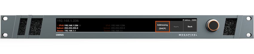
Table of Contents

                            1
                            System Components                          1
                                Overview                                2
                                Front Panel                             3
                                Rear Panel                              5
                            2
                            Connections                                6
                                Overview                                6
                                IP Addressing - Front LCD               8
                                IP Addressing - Web App                 9
                            3
                            Configuration                              10
                                Overview                               10
                                Systems                                10
                                Devices                                13
                                Displays                               15
                                Settings                               16
                                General - Tab                          17
                                Cloud - Tab                            20
                                About - Tab                            21
                            4
                            Monitoring                                 22
                                Overview                               22
                                Health Map                             22
                                Temperatures Map                       25
                                Alerts                                 26
                                Log                                    28
                            5
                            Maintenance & Accessories                  30
                                General Maintenance                    30
                                Filter Maintenance                     30
                            A
                            Technical Specifications                   31
                                OMNIS Processor - Shipping Info.       32
                                OMNIS Processor Dimensions             32

OMNIS AV Monitoring System - USER GUIDE                            i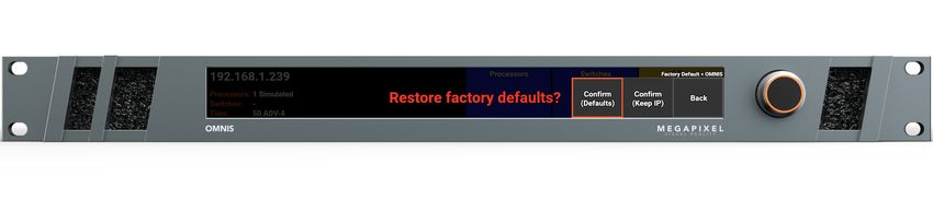
Legal
      Copyright © Megapixel Visual Reality®.

      The Megapixel VRTM logo is a trademark of H2VR HoldCo, Inc. Other trademarks and trade names may be
      used in this document to refer to products by other entities. Megapixel VR claims no proprietary interest in
      trademarks and trade names owned by others.

      Information and specifications in this document are subject to change without notice. Megapixel VR assumes
      no responsibility or liability for any errors or inaccuracies that may appear in this manual.

      Contact
      +1 818 884 5488

      http://megapixelvr.com

      Safety Information
      The symbols below are used throughout this manual to identify important safety information. Heed all
      warnings and safety information.

                                 Symbol     Meaning

                                            Warning, Danger, or Caution
                                            Risk of injury to yourself or the product.

                                            Risk of Electrical Shock
                                            Risk of severe electrical shock.

      Warranty Information
      Megapixel VR warrants the OMNIS®, a hardware product, against defects in materials and workmanship
      under normal use for a period of one (1) year from the date of retail purchase by the original end-user
      purchaser.

      Megapixel VR does not warrant that the operation of the product will be uninterrupted or error free.
      Megapixel VR is not responsible for damage arising from failure to follow product or installation instructions.

OMNIS AV Monitoring System - USER GUIDE                      ii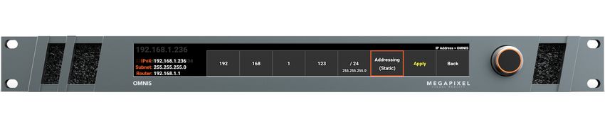
Installation Environment
      The OMNIS is designed to be rack mounted in a central control room for fixed installations or flight cased for
      touring applications.

      The unit has been qualified to operate in a dry environment within a temperature range of 15°C to 40°C (59°F
      to 104°F).

                  NOTE: Never obstruct the airflow to the side ventilation slots. The front filters need to be regularly
                  checked and cleaned.

                  WARNING: Below is a set of environmental conditions that must be met prior to installing
                  Megapixel VR products. The installation and/or use of products in these environments not
                  meeting these conditions may void all warranties.

                      ▪    Installation locations must be free of moisture.

                      ▪    Installation locations must be dust free.

                      ▪    All heavy and dirty site work must be complete. This includes re-working or
                           modifications to walls, ceiling and floor.

                      ▪    All construction materials and debris must be removed, area swept, vacuumed
                           cleaned, and floor wet-mopped.

                      ▪    Building structure, roof, and walls are sealed and weather proofed. Roof successfully
                           tested for leaks.

                      ▪    Outside drainage system and floor drains checked and tested to protect the
                           equipment from flooding.

                      ▪    Floors sealed and cleaned.

                      ▪    All doors and windows installed and operational with weather seals.

                      ▪    All final wall preparation complete including all taping, joint compound and fire
                           sealant. Walls to be primed and finish painted.

                      ▪    Overhead fire sprinkler or suppression system installed and pressure tested.

                      ▪    HVAC ducts blown free of debris. HVAC shall be operational/balanced and running
                           72 hours prior to equipment installation.

OMNIS AV Monitoring System - USER GUIDE                         iii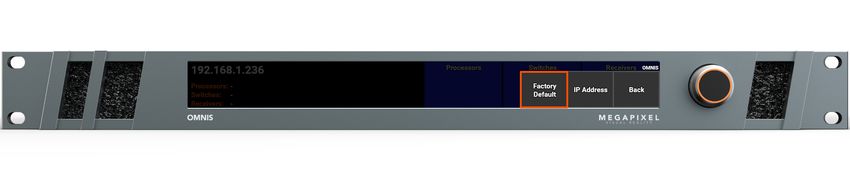
FCC Statement
      This equipment has been tested and found to comply with the limits for a class A digital device, pursuant to
      Part 15 of the FCC rules. These limits are designed to provide reasonable protection against harmful
      interference when the equipment is operated in a commercial environment.

      This equipment generates, uses, and can radiate radio frequency energy. If the equipment is not installed and
      used as directed in the instruction manual, it may cause harmful interference to radio communications. It is
      the responsibility of the user to correct any interference.

      Carrying and Handling the Equipment
      Before you handle the OMNIS, disconnect all cables and cords. Do not operate the OMNIS in areas with
      significant amounts of airborne dust or smoke, or near a humidifier. Tiny airborne particles can damage the
      equipment.

      Liquid Exposure
      Keep the OMNIS away from all sources of liquid. Protect equipment from dampness, humidity, or wet weather,
      such as rain, snow, and fog.

      Power
      Unplug the power cord (by pulling the connector, not the cord) and disconnect all other cables if any of the
      following conditions exist:

          ▪    The power cord or plug becomes frayed or otherwise damaged.

          ▪    Liquid has spilled onto the equipment.

          ▪    The equipment is exposed to rain or excess moisture or humidity.

          ▪    The equipment has been dropped, and has been damaged.

          ▪    You suspect that the equipment needs service or repair.

          ▪    You want to clean the case (use only the recommended procedure, described later in this document).

                  IMPORTANT: The only way to completely turn off power is to unplug the power cord.

                  WARNING: The AC cord has a three-wire grounding connector. This connector fits only a
                  grounded AC outlet. If you are unable to insert the connector into an outlet because the outlet
                  isn’t grounded, contact a licensed electrician to replace the outlet with a properly grounded one.
                  Do not defeat the purpose of the grounding pin.

OMNIS AV Monitoring System - USER GUIDE                       iv
Repairing
      The OMNIS does not have any user-serviceable parts. Do not attempt to replace or repair any components
      inside the equipment. If the equipment needs service, contact the company that provided or installed the
      equipment. If you open the equipment or install items, you risk damaging the equipment. Such damage isn’t
      covered by the limited warranty on the equipment.

      Medical Device Interference
      The OMNIS contains components that emit electromagnetic fields, which may interfere with pacemakers,
      defibrillators, or other medical devices. Maintain a safe distance of separation between your medical device
      and equipment. Consult your physician and medical device manufacturer for information specific to your
      medical device. If you suspect equipment is interfering with your pacemaker or any other medical device,
      stop using the equipment.

      Medical Conditions
      If you have a medical condition that could be affected by using an OMNIS (i.e., seizures, blackouts), consult
      with your physician prior to using the OMNIS.

      High-Consequence Activities
      The OMNIS is not intended to be used where failure could lead to death, injury, or severe environmental
      damage.

      Explosive Atmospheres
      Using the OMNIS in any area with a potentially explosive atmosphere (i.e. where the air contains high levels of
      flammable chemicals, vapors, or particles (such as grain, dust, or metal powders), may be hazardous. Obey all
      signs and instructions.

      Using Connectors and Ports
      Never force a connector into a port. When connecting a device, make sure the port is free of debris, that the
      connector matches the port, and that you have oriented the connector correctly in relation to the port.

      Storing the Equipment
      If you are going to store the OMNIS for an extended period of time, keep it in a cool and dry location (ideally,
      71° F or 22° C).

OMNIS AV Monitoring System - USER GUIDE                      v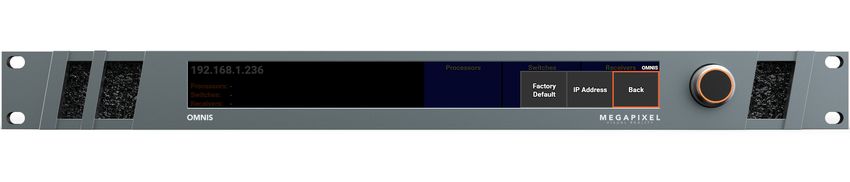
Cleaning the Equipment
      When cleaning the outside of the OMNIS and its components, first shut down the equipment, then unplug all
      cords and cables. Use canned air such as ‘Turbo Blast’ by ACL Staticide Inc. or a clean, soft, lint-free cloth to
      wipe the equipment exterior. Avoid getting moisture in any openings. Do not spray liquid on the equipment.
      Do not use sprays, solvents, abrasives, or cleaners.

      Changes
      Megapixel VR provides this manual ’as is’ without warranty of any kind, either expressed or implied, including
      but not limited to the implied warranties or merchantability and fitness for a particular purpose. Megapixel VR
      may make improvements and/or changes to the product(s) and/or the program(s) described in this
      publication at any time without notice.

      This publication could contain technical inaccuracies or typographical errors. Changes are periodically made
      to the information in this publication; these changes are incorporated in new editions of this publication.

      Certifications
        Megapixel VR

        5015417

OMNIS AV Monitoring System - USER GUIDE                       vi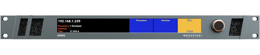
1
                                                                        System Components

      The OMNIS is a specialized rack mount network appliance designed to manage large arrays of video walls. It
      aggregates up to 200 video processors into a single map view. The 'at a glance’ real-time system status
      information can monitor a wide range of system status information including monitoring the temperature, link
      status, power supply status, and integrity of data flowing into and out of display devices. This assists, with
      rapid diagnosis and in some cases resolving issues before a failure impacts the visual quality of the display.

      The OMNIS provides four key services:

      •   System overview of all connected devices

      •   Notifications of events for connected devices

      •   Quick access to common tasks (Brightness, screen blanking)

      •   In depth device status details

OMNIS AV Monitoring System - USER GUIDE                     1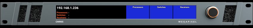
Overview
      The OMNIS is a one RU (1.75”) tall rack mount unit.

      The OMNIS has eight WAN ports for monitoring. All eight of these ports are assigned the same monitoring IP
      address. The OMNIS also has four LAN ports for system management and control. These four ports are all
      assigned the same management IP address.

      The system is configured remotely via a web app that can be hosted on a laptop or tablet running Chrome or
      Safari browsers.

                                                     Figure 1: OMNIS

OMNIS AV Monitoring System - USER GUIDE                     2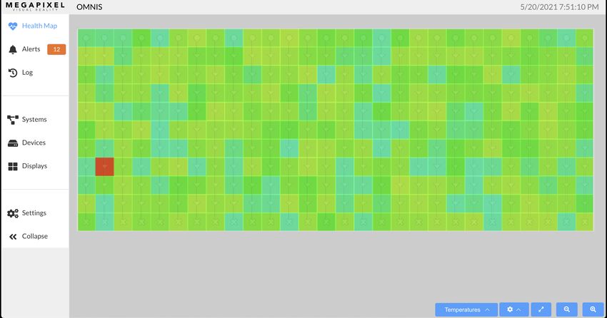
Front Panel
     1 - Configuration interface - On front of the OMNIS is an LCD display and a turn/push knob interface.
     Turning the front encoder knob will switch the front LCD interface between two views; Home and Details
     (described in the section below).

     2 - Air inlets - slots to the left and right of the LCD display are filtered vents for chassis airflow.

                                                Figure 2: OMNIS front panel items

     Front panel interface views

     Turning the front encoder knob, without pressing it, will switch the front LCD interface between two views;
     Home and Details. The Home view displays colored rectangles as status indicators for key parts of a system.
     The Details view contains additional information regarding the OMNIS system such as firmware version and
     detailed IP settings.

     Home

     Details

                                                Figure 3: OMNIS front LCD views

OMNIS AV Monitoring System - USER GUIDE                          3
Main Menu
Press the encoder to enter the main menu. The main menu has two options; restore Factory Default and IP
Address. Please see the IP Addressing section for details on setting the IP.
Figure 4: OMNIS Menu options
Restoring to Factory Default
1. Select Factory Default.
2. Select from two options, after selection, the OMNIS will reboot.
• Confirm (Defaults) - all information will be restored to factory defaults.
• Confirm (Keep IP) - all information will be restored to factory defaults, except the IP address. Use this
option in cases where the unit needs to rejoin the same network after the restore.
All current show information will be deleted!
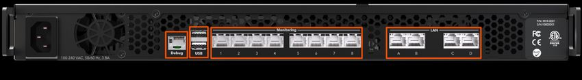
OMNIS AV Monitoring System - USER GUIDE 4Rear Panel
1 - Debug - Serial port for development purposes.
2 - USB - Local USB device monitoring port. This port does not provide access to the user interface.
3 - Monitoring - WAN ports for connecting to the monitored display’s network. HELIOS connects here.
4 - LAN - System management and control ports. Connect a laptop here for access to the WebUI.
Figure 5: OMNIS rear
OMNIS AV Monitoring System - USER GUIDE 52
Connections
Overview
The OMNIS system consists of; the OMNIS processor, the system it is monitoring and the network connections in between.
Connections
Power - A/C power is supplied to the OMNIS on a C14 style IEC connector. There is no power switch. When power is
applied, the system will begin to boot. After about 15 seconds the front screen will be lit. When the boot logo disappears,
the OMNIS is ready for use.
Monitoring Ports - Connect the control ports of a HELIOS display processor to the monitoring ports to have the OMNIS
system automatically discover the system topology. Remember to assign all devices to the same LAN manually or use
DHCP if available.
User Interface - The OMNIS system can be used with a wide variety of LED display products. It is necessary to configure
the system to the products in use. Configuration of the OMNIS System is accomplished with a web application. The web
app runs on any remote host capable of running a modern web browser such as Chrome or Safari. In order to
communicate with the OMNIS System, the web app host must be configured to be on the same LAN as the OMNIS.
OMNIS AV Monitoring System - USER GUIDE 6Figure 6: System diagram Note: For convenience or compatibility with wireless-only devices such as tablets, a wireless router can be attached to the OMNIS LAN ports. OMNIS AV Monitoring System - USER GUIDE 7
IP Addressing - Front LCD
The IP address of the OMNIS is reported on the front display of the OMNIS.

A factory reset OMNIS will be set to DHCP by default. DHCP is the mode that should be used when operating the OMNIS
with a wireless router attached to one of the control ports. If the OMNIS has discovered a DHCP server, the OMNIS will
likely have a 192.168.XX.YY address. If it has not been served an IP address by DHCP, the OMNIS will default to an
automatic private address (169.254.XX.YY). In DHCP mode, the web UI host device must also be set to DHCP in order to
join the same network.

The OMNIS can be configured to a fixed IP as well. In fixed IP mode, ensure both the IP and the subnet mask for the web
app host have been set to the correct range.

1. Press the encoder on the front of the OMNIS unit, then turn the encoder to select IP Address.

2. If the unit reports Addressing (DHCP) the unit is set to automatically acquire an IP from a DHCP server. Select
   Addressing (DHCP) or Addressing (Static) to select between DHCP or Static IP, depending on the network that the
   OMNIS needs to join.

3. Once the IP settings have been made, select Apply.

OMNIS AV Monitoring System - USER GUIDE                     8
IP Addressing - Web App
The IP address of the OMNIS can also be set from the web app interface. Select Settings > Network. If the client and the
OMNIS are not on the same network the user interface will not be available. Be certain of the settings before pressing
apply.

                                             Figure 7: Web app network settings

OMNIS AV Monitoring System - USER GUIDE                      9
3
Configuration
Overview
Prior to configuring the system, a majority of the components of the system should be physically connected. At minimum,
the OMNIS should be connected to at least one monitoring target processor such as HELIOS. In the previous chapter on
connections, this guide has IP addressing instructions for both the OMNIS and the client device (tech laptop). The web UI
requires an IP network.
Systems
Enter the IP address of the target OMNIS into the search bar of Chrome or Safari on the tech laptop or tablet. The first
steps to configuring an OMNIS processor is to navigate to the Systems pane and press the Add System button.
Figure 8: Add System
OMNIS AV Monitoring System - USER GUIDE 10Provide the target device details to OMNIS. After devices have been added, they will be listed in the Systems pane.
Figure 9: Add System
In the Systems pane, connected systems appear as a list with a row assigned to each system.
1 2 3
Figure 10: Systems list
1. URL - Visit the UI of a HELIOS by clicking on the URL.
2. System name - Edit the system by selecting the blue system name.
OMNIS AV Monitoring System - USER GUIDE 113. Baseline - In the OMNIS system, a baseline is a comprehensive set of data points that OMNIS stores to create a snapshot of the system. OMNIS uses the baseline as a point of comparison. A baseline is created after a system has been configured and is expected to not change. Once a new system is fully operational with no alerts or issues, press the Baseline button to have the OMNIS record the current state. The OMNIS will monitor and notify with a deviation alert if it detects a change from the baseline. As an example, a panel moving to a new location on the raster map is not an alert worthy event unless it happens after a system has been baselined. Once the baseline data points have been recorded, OMNIS has fixed points of reference to compare to. When parameters change such as map position, a baselined system will alert with a deviation for all parameters that are affected by the change. More than one deviation alert can occur for a single event if the event affects more than one parameter. Please see the Alerts section in Chapter 4w for more information on alerts and deviations. NOTE: Novastar processors have a known issue being monitored by OMNIS while simultaneously being controlled from their proprietary software. The Novastar interface can be quite unresponsive and unreliable. This is due to the fact that the Nova processor can only support a single connection at a time. OMNIS must be temporarily disconnected to eliminate the erratic behavior. To do this, edit the Novastar system and change the access to Disabled. OMNIS AV Monitoring System - USER GUIDE 12
Devices
The devices pane lists all connected devices. Devices are grouped by type, Processors listed first. Tiles have their own tab.

                                                       Figure 11: Devices

Network switches is a list of all network switches in a system. Expand each to view switch port information. This view gives
a dashboard view of detailed information for all the ports in a system. Ports are laid out in numerical order, with each ‘cell’
representing one port on the switch.

                                                  Figure 12: Network switches

OMNIS AV Monitoring System - USER GUIDE                        13
1
2
3
4
5
1. Port number - of the connected HELIOS. HELIOS units have eight (8) possible ports. The HELIOS name is
automatically set by HELIOS on connecting to the switch to identify the main display data input to the switch.
2. Port address - This is standard networking equipment port addressing for NETGEAR switches. Unit number / Slot
number/ Port number. Smaller switches that do not have modular slots will not have the middle slot number. If there
are only two numbers here they stand for Unit / Port.
3. Link speed - The speed that the system is connected on this port.
4. VLAN label - Short names are preferable and should be named according to the function in the system.The [1] default
label is reserved for inbound HELIOS data. Tile ports will be labeled with their VLAN ID and Tile Data port number.
[101] Tile Data 1
5. In / Out bound data as percent of port link speed.
OMNIS AV Monitoring System - USER GUIDE 14Displays
The Displays pane contains the controls for the visible aspects of a display such as which input is in use, test patterns,
blackout etc. Select the system name from the tab at the top to begin controlling a display. The health map offset at the
bottom of the pane, controls the position of the display in the health map view of OMNIS.
Figure 14: Devices
OMNIS AV Monitoring System - USER GUIDE 15Settings
The Settings pane contains three tabs for General, Cloud and About.
Figure 13: Settings
OMNIS AV Monitoring System - USER GUIDE 16General - Tab
The General accordion contains a toggle for enabling display controls. These controls have an identical function to the
ones found on the HELIOS UI. They allow for live adjustment of a display’s brightness and gamma, pause and blackout of a
display.
Figure 15: Display controls OFF
Figure 16: Display controls ON
Pause - will continuously display a still image of the last input frame at the time pause was pressed. This feature is
convenient to use when the input signal must be interrupted, and the live display can show a still image such as a logo. To
use this feature, display the desired image and press the pause button. The input signal can now be interrupted and the
HELIOS Processor will continue to display the still frame grab. When it comes time to resume, display the same image
again with the connected playback device and toggle pause off to resume live playback.
Blackout - is a black generator that ensures all LEDs are completely off. This feature is ideal to use for situations when
panels need to be placed on stand-by with power use at a minimum.
OMNIS AV Monitoring System - USER GUIDE 17General - Tab (Continued)
OMNIS License accordion contains a unique System ID that is required when obtaining a license. This is also the location
to upload a license file. License files can be obtained directly from MVR. Please contact your MVR representative for more
information.
Figure 17: OMNIS License
Reset accordion contains the Reset button which returns a unit to factory defaults.
Figure 18: Reset
OMNIS AV Monitoring System - USER GUIDE 18General - Tab (Continued)
Software update accordion reports the current version and provides the Upload update package function. Press the
button and navigate top the OMNIS .mvrp package to be installed.
Figure 19: Software update
Once the .mvrp package is selected, the OMNIS will warn that the system will go offline as part of the upgrade process.
Figure 20: Update warning
OMNIS AV Monitoring System - USER GUIDE 19Cloud - Tab
Enable Cloud settings to have OMNIS send email notifications. Email notifications require a cloud license. Please contact
your MVR representative for this license.
Figure 21: Settings Cloud
OMNIS AV Monitoring System - USER GUIDE 20About - Tab
The About tab displays the current OMNIS version number along with some important links for contacting support. Press
the Download support archive button to save a zip file containing OMNIS system information files that are essential to
obtaining new system licenses and are helpful for troubleshooting.
Figure 22: Settings About
OMNIS AV Monitoring System - USER GUIDE 214
Monitoring
Overview
Once the system setup has been completed, OMNIS continuously monitors the connected system(s). OMNIS can display
two different visualizations of system information; Health and Temperature. These views are of the display the system(s) as
viewed from the front of the display. The Health view shows the system connectivity and alerts (if there are any). The
Temperature view shows the temperature of each panel’s CPU mapped to colors, plus any related alerts.
Health Map
The Health Map is the top item in the nav bar. In this pane, OMNIS displays the panels visually as they are mapped. Panels
are shown as square or rectangular icons. The processor name for each system appears in large letters across all
respective panels. Panels operating with no issues are shown in blue.
Figure 23: Health Map
OMNIS AV Monitoring System - USER GUIDE 22Orange panels such as the ones shown below, indicate that the system has raised an alert for that panel. Select a panel
icon to reveal alert details.
Figure 24: Alert card
Overlaid on the panel icons, are connectivity symbols. A circle represents a processor connection, a triangle arrow shows
the direction of the data flow, and an X represents the end of a string of panels.
Figure 25: Connectivity symbols
OMNIS AV Monitoring System - USER GUIDE 23Details about the display can be viewed by selecting the entire display. A pop up menu will appear with four tabs;
Receivers, Processors, Display, and Offset.
Figure 26: Offset
OMNIS AV Monitoring System - USER GUIDE 24Temperatures Map
The Temperatures map shows the temperatures of panels. Temperatures are indicated in a rainbow palette that shows
thermal differences in 5º degree increments.
Figure 27: Color to temperature
In the example below, one panel has raised an alert with a CPU at 90ºC. Use this view to quickly identify any temperature
anomalies in the system. The temperature map is not just useful for recognizing panels that are excessively hot. It is good
practice to warm LED panels up prior to being used at full brightness. Use the temperature map to monitor progress and
to confirm when panels are ready for use.
OMNIS AV Monitoring System - USER GUIDE 25Alerts
The OMNIS front display will show a color code for the region of the system (Processors, Switches, or Receivers) that the
alert corresponds to when a system has at least one active alert.
Color Decoder
OK
Notice
Warning
Error
Critical
Figure 28: OMNIS front panel alert
The OMNIS UI will display all active alerts and deviations as a badge next to the alert pane select. In the alerts pane, alerts
can be viewed in two different ways; Active and Deviations.
Figure 29: Alerts pane
OMNIS AV Monitoring System - USER GUIDE 26Alerts (Continued)
Active - a list of current issues in the system. As issues are resolved OMNIS will automatically clear this list.
Deviations - a list of alerts that are generated when the OMNIS detects changes to the baseline. Please see the section on
Baseline for more information about using this feature. The Accept button removes the deviation from the current list and
also removes the highlight from the alert in the alert log. The Accept button also updates that associated system(s)
baseline with that deviation. When panels are replaced in a system, each panel change will cause a deviation. Use the
Accept button to update the system to use using the new panels. If the input type is changed (i.e. DP -> HDMI) OMNIS will
flag that as a deviation. When this change is accepted, OMNIS will flag a deviation if the input changes.
Figure 30: Alerts Active / Deviations
OMNIS AV Monitoring System - USER GUIDE 27Log
The Log pane displays a historical view of all alerts. After active alerts are cleared, they can still be found in the Log pane.
When navigating long log records looking for specific types of alerts, it can be helpful to use the filters at the top of the
page.
Figure 31: Log pane
OMNIS AV Monitoring System - USER GUIDE 28Log (Continued)
Press the pencil icon to tag or comment on a line. Tagging can be very useful for adding details about system events to
help set them apart from the rest. Create tags as they are needed by selecting a word or phrase that can be consistently
reused. A person’s name could be used to let them easily identify which alerts they need to deal with, or simply create the
‘ignore‘ tag for items that do not need attention.
Figure 32: Notes and Tags
OMNIS AV Monitoring System - USER GUIDE 295
Maintenance & Accessories
General Maintenance
Proper maintenance of the OMNIS involves periodically checking the hardware for any parts that may have come loose or
become damaged. Connectors should be checked and the unit replaced if housings have become damaged or pins are
bent or deformed.
Filter Maintenance
The front filter on the air intake ducts of the OMNIS should be periodically cleaned. Gently pry the foam filter out and
clean or replace the filters.
Figure 33: Remove air intake filters for service.
OMNIS AV Monitoring System - USER GUIDE 30A
Technical Specifications
Dimensions (W x H x D) 482mm (19.0”) x 44mm (1.7”) x 415mm (16.3”)
Power Requirements 100 - 240V AC, 50Hz/60Hz, 3.8A (IEC C14 Connector)
Weight 3.9 kg (8.6 lb) shipping dimensions and weights on the next page
IP Rating Indoor
Ambient Operating Temperature 15º - 40ºC (59º - 104ºF)
Certifications ETL, FCC (Class A), CE, RoHS
Maximum Panels to monitor TBD
Maximum Processors to monitor 200
Heat Load 256 BTU/hr thermal dissipation
OMNIS web app 1 x Gigabit Ethernet
OMNIS AV Monitoring System - USER GUIDE 31OMNIS Processor - Shipping Info.
Shipping box dimensions (W x H x D) 533mm (21”) x 597mm (23.5”) x 184mm (7.25”)
OMNIS 7.8kg | 17.1 lb
OMNIS Processor Dimensions
Front View
44mm
482mm
Top View
436mm
3mm
20mm
393mm
415mm
23mm
6mm
11mm
11mm
482mm
Figure 34: OMNIS dimensions
OMNIS AV Monitoring System - USER GUIDE 32The OMNIS is running a Linux build called MegaOS which is based on Alpine. The following network ports & services are
used by the system:
Network Ports Notes
22 (SSH) Only through private key authentication for developers
80 (HTTP) Main Web UI and Public API
1900 (UPnP) Service Discovery
5353 (Multicast DNS) Service Discovery
OMNIS AV Monitoring System - USER GUIDE 33You can also read