Network Configuration Example: EX Series Switches Driven by Mist AI - Network Configuration Example - Juniper Networks
←
→
Page content transcription
If your browser does not render page correctly, please read the page content below
Network Configuration Example

Network Configuration Example: EX Series
Switches Driven by Mist AI

  Published
 2021-03-16
ii

  Juniper Networks, Inc.
  1133 Innovation Way
  Sunnyvale, California 94089
  USA
  408-745-2000
  www.juniper.net

Juniper Networks, the Juniper Networks logo, Juniper, and Junos are registered trademarks of Juniper Networks, Inc. in
the United States and other countries. All other trademarks, service marks, registered marks, or registered service marks
are the property of their respective owners.

Juniper Networks assumes no responsibility for any inaccuracies in this document. Juniper Networks reserves the right
to change, modify, transfer, or otherwise revise this publication without notice.

Network Configuration Example Network Configuration Example: EX Series Switches Driven by Mist AI
Copyright © 2021 Juniper Networks, Inc. All rights reserved.

The information in this document is current as of the date on the title page.

YEAR 2000 NOTICE

Juniper Networks hardware and software products are Year 2000 compliant. Junos OS has no known time-related
limitations through the year 2038. However, the NTP application is known to have some difficulty in the year 2036.

END USER LICENSE AGREEMENT

The Juniper Networks product that is the subject of this technical documentation consists of (or is intended for use with)
Juniper Networks software. Use of such software is subject to the terms and conditions of the End User License Agreement
(“EULA”) posted at https://support.juniper.net/support/eula/. By downloading, installing or using such software, you
agree to the terms and conditions of that EULA.
iii

Table of Contents

1    Using Juniper EX Series Switches with the Juniper Mist Cloud
     Overview of EX Series Switches and the Juniper Mist Cloud | 5

     Day 0: Add an EX Series Switch to the Juniper Mist Cloud | 7

     Day 1: Use a Template-Based Configuration with Device and Port Profile | 16

        Configuration Templates | 18

        Case 1: Organization-Level Switch Settings | 20

        Case 2: Network-Level Settings | 21

        Case 3: Individual Switch Administration | 22

        Dynamic Port Profiles | 24

        Configure Network Access | 25

        Add a Port Profile | 27

        Configure a Dynamic Port | 30

        Associate Ports | 33

        Virtual Chassis | 34

        Design Considerations for Virtual Chassis | 35

        Virtual Chassis on EX2300 Switches with the Juniper Mist Cloud | 37

        Virtual Chassis on EX3400 and EX4300 Switches with the Juniper Mist Cloud | 39

     Day 2: Wired User Service Level Expectations, Switch Events, and Marvis Actions | 42

     Manual EX Series Switch Configurations | 42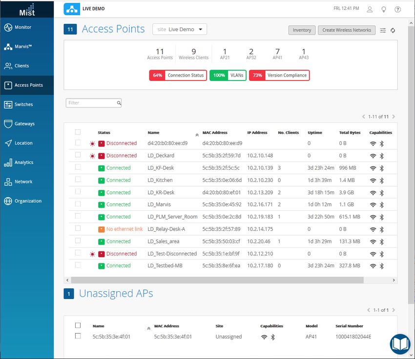
1 CHAPTER

Using Juniper EX Series Switches with
the Juniper Mist Cloud

Overview of EX Series Switches and the Juniper Mist Cloud | 5

Day 0: Add an EX Series Switch to the Juniper Mist Cloud | 7

Day 1: Use a Template-Based Configuration with Device and Port Profile | 16

Day 2: Wired User Service Level Expectations, Switch Events, and Marvis
Actions | 42

Manual EX Series Switch Configurations | 42
5

Overview of EX Series Switches and the Juniper Mist
Cloud

 This example uses Junos OS Release 18.4R2.7 running on a Juniper Networks EX3400 switch with
 connections from Juniper access points. All the features you need to set up interoperability between the
 access points with EX Series switches are available in Junos OS Release 18.4R2.7 and later.

 We recommend Juniper EX Series switches for interoperability with Juniper access points driven by Mist
 AI. These devices support Juniper’s Virtual Chassis, which we discuss later in this NCE, and provide Power
 over Ethernet (PoE) network interfaces and supply 8, 24, or 48 multigigabit ports that comply with IEEE
 802.3af standards (such as delivering a regulated 15.4 watts of power).

 Figure 1: Physical Connections Between Juniper EX Series Switches and Access Points in a NOC

 EX Series switches also support PoE+, which extends normal operation to comply with IEEE 802.3at
 standards. PoE ports are typically used to connect VoIP telephones, wireless access points, video cameras,
 point-of-sale devices, and other such devices because they safely deliver power from the interface
 connection over a copper Ethernet LAN cable, and provide the necessary scale.

 We recommend using any of the EX Series switches shown in the following table. They meet both the
 PoE and speed requirements needed for access point deployments, and they support Juniper’s Virtual
 Chassis.
6

Table 1: Recommended EX Series Switches for Use with Juniper Access Points

 Switch                  PoE                                    Speed                         Juniper Access Points

 EX2300                  PoE+ (IEEE 802.3at)                    1GbE                          AP21, AP41, AP61, AP43 (no-mg

 EX2300-C                PoE+ (IEEE 802.3at)                    1GbE                          AP21, AP41, AP61, AP43 (no-mg

 EX2300 MP               PoE+ (IEEE 802.3st)                    1GbE/2.5GbE                   AP21, AP41, AP61, AP43

 EX3400                  PoE+ (IEEE 802.3at)                    1GbE                          AP21, AP41, AP61, AP43 (no-mg

 EX4300-P                PoE+ (IEEE 802.3st)                    1GbE                          AP21, AP41, AP61, AP43 (no-mg

 EX4300 MP               PoE+ (IEEE 802.3st)                    1GbE/2.5GbE/5GbE/10GbE        AP21, AP41, AP61, AP43

                         PoE (IEEE 802.3br)

 EX4400                  PoE++ (IEEE 802.3bt)                   1GbE/2.5GbE/5GbE/10GbE        AP21, AP41, AP61, AP43

                         PoE+ (IEEE 802.3at)

Cloud-ready, or “greenfield,” switches can be automatically added to the Juniper Mist cloud services using
the zero-touch provisioning (ZTP) option, and then adopted in the Juniper Mist portal.

“Brownfield” switches, that is, existing switches that may have been used in a previous deployment, can
also be added to the Juniper Mist cloud.

In either case, the switch needs to connect to a Domain Name System (DNS) server – a Network Time
Protocol (NTP) server is also recommended – and it needs to be able to connect to the Juniper Mist cloud
over the Internet. If there is a firewall between the cloud and the switch, you need to allow outbound
access on TCP port 2200 to the management port of the switch.

We recommend that all switches added to the Juniper Mist cloud be managed exclusively through the
Juniper Mist portal, and not from the device’s CLI. The Juniper Mist portal provides the user interface, and
includes AI-driven cloud services and architecture. You can access these through your Juniper Mist account.

The Juniper website provides extensive documentation on both the Junos operating system and the EX
Series hardware used in this NCE. Likewise, you can find documentation on Juniper Mist Premium Analytics
including configuration details for Juniper access points on mist.com.

RELATED DOCUMENTATION

   Junos documentation
   EX Series documentation for: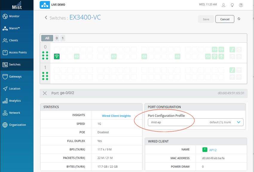
7

  •EX2300
  •EX3400
  •EX4300
  •EX4400

  Juniper Mist Wireless LAN Documentation
  Juniper Mist documentation

Day 0: Add an EX Series Switch to the Juniper Mist
Cloud

   IN THIS SECTION

       Requirements | 8

       Overview of the ZTP Process | 8

       How to Activate a Greenfield Switch | 9

       Activate a Brownfield Switch | 11

       Add the Switch to the Juniper Mist Cloud Architecture and View Details | 14

       Troubleshooting | 16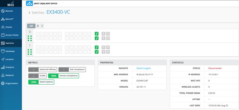
8

Requirements

We recommend that all switches in an organization be managed exclusively through the Juniper Mist
cloud, and not from the device’s CLI.

The switch needs to connect to a DNS server (an NTP server is also recommended), and it needs to be
able to connect to the Juniper Mist cloud architecture over the Internet. If there is a firewall between the
cloud and the switch, you need to allow outbound access on TCP port 2200 to the management port of
the switch. In addition, you need the following items:

• A Juniper Mist Wired Assurance Subscription, and logon credentials for the Juniper Mist portal

• Physical access to the switch to connect the cables

• A supported Juniper EX Series switch

• A user account on the switch to make CLI configurations (brownfield option)

This example shows how to connect an EX Series switch to the Juniper Mist cloud architecture, and how
to bring it onboard to your organization in the Juniper Mist portal. Cloud-ready, or “greenfield” switches
can be automatically added to the Juniper Mist cloud using the ZTP option, or they can be added manually
by entering an activation code for the switch in the Juniper Mist portal.

Figure 2: Cloud-Ready Switches

“Brownfield” switches, that is, switches being brought into the Juniper Mist cloud architecture from a
previous deployment, can also be added to the Juniper Mist cloud. Both procedures are described in this
example.

Overview of the ZTP Process

Once a cloud-ready switch is connected to the Internet and powered on for the first time, it triggers an
onboard phone-home client (PHC) to get configuration updates from the phone-home server (PHS) as
shown in Figure 3 on page 9. The default behavior is for the PHC to connect to a redirect server, which
then redirects it to a phone home server where the switch can get the configuration or software image.
This enables the switch to securely and automatically obtain the most recent Junos OS configuration or
software image, with no intervention other than physically connecting the switch to the network.
Alternatively, you can configure the switch to use a Dynamic Host Configuration Protocol (DHCP) server

9

configured with the necessary ZTP options to complete the ZTP process. To revert to the ZTP default,
you need to boot from the factory-default state (or you can issue the Junos OS request system zeroize
command to reset the configuration).

Topology

Figure 3: ZTP Process for EX Series Switches

How to Activate a Greenfield Switch

    IN THIS SECTION

         Manually Add a Cloud-Ready Switch to the Juniper Mist Cloud: | 9

To adopt a cloud-ready switch manually, you need an activation code for the switch. Activation codes are
sent through e-mail to the address on record at the time of purchase, or they can be obtained by contacting
the Juniper Mist Customer Engagement team. Using the activation code adopts the switch and any Juniper
access points that are part of the purchase order, as well as claims any subscriptions that are included in
your purchase.

Manually Add a Cloud-Ready Switch to the Juniper Mist Cloud:

Step-by-Step Procedure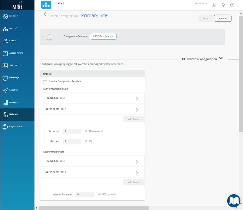
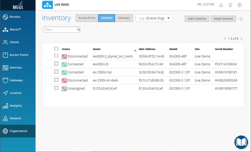
10

1. Start by unboxing your switch, connecting the management port to the Internet, and powering it on.
   As part of the ZTP process, the switch automatically accesses the PHC server (or the DHCP server if
   you have set this up instead) and then connects to the Juniper Mist cloud for configuration updates.

2. Using a Web browser, log in to your Juniper Mist account. The Monitor page appears, showing an
   overview of the Juniper Mist cloud and any Juniper access points and clients that are already connected.
   In the menu on the left, click Organization > Inventory to open that page.

Figure 4: The Juniper Mist Inventory Page

3. Select Switches at the top of the Inventory page, and then click the Claim Switches button and enter
   the activation code for the switch.

Figure 5: The Claim Switches Page

4. Fill out the other fields on the page as you like. Select Manage configuration with Juniper Mist and
   then enter a root password for the switch. Note that this choice puts the switch under the management
11
of the Juniper Mist portal, and as such, we recommend that local configuration using the CLI be restricted
to prevent conflicts (for example, you might want to create a system login message on the switch to
warn against making configuration changes locally, from the CLI).
Once the ZTP process resolves, the switch automatically appears in the Inventory page. If the switch
doesn’t appear after a few minutes, despite refreshing the web page, log out and then log back in.
Activate a Brownfield Switch
IN THIS SECTION
How to Add a Brownfield Switch to the Juniper Mist Cloud | 11
It is important to back up your existing Junos OS configuration on the switch before activating a brownfield
switch because when the switch is adopted for management from the Juniper Mist cloud, the old
configuration is replaced. Back up your existing Junos OS configuration by running the request system
software configuration-backup (path) command, which saves the currently active configuration and any
installation-specific parameters.
Likewise, To prevent users from using the Junos CLI to configure the switch after it has been adopted into
the Juniper Mist cloud, you may want to create a system login message on the switch to warn against
making configuration changes, or to restrict their management access altogether by changing the password
or placing restrictions on the Junos CLI user accounts.
How to Add a Brownfield Switch to the Juniper Mist Cloud
Step-by-Step Procedure
This procedure describes how to set up a secure connection between a supported EX Series switch running
a supported version of Junos OS. In it, you will make a few configuration changes to the Juniper Mist
portal, and some to the switch using the Junos OS CLI. Be sure you can log in to both systems.
1. Log in to your organization on the Juniper Mist cloud and then click Organization > Inventory in the
menu.
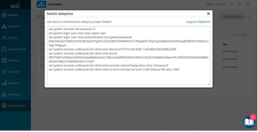
2. Select Switches at the top of the page that appears, and then click the Adopt Switch button in the
upper-right corner to generate the Junos OS CLI commands needed for the interoperability. The
commands create a Juniper Mist user account, and a SSH connection to the Juniper Mist cloud over12
TCP port 2200 (the switch connection is from a management interface and is used for configuration
settings and sending telemetry data).
Figure 6: The Switch Adoption Page
3. In the page that appears, click Copy to Clipboard to get the commands from the Juniper Mist cloud.
4. In the Junos OS CLI, type edit to start configuration mode, and then paste the commands you just
copied (type top if you are not already at the base level of the hierarchy).
5. If you want to add a system message, use the following command:
user@host# set system login message message text here
6. You can confirm your updates on the switch by running show commands at the [system services] level
of the hierarchy, and again at the [system login user juniper-mist] level of the hierarchy.
show system services
ssh {
protocol-version v2;
}
netconf {
ssh;
}
outbound-ssh {13
client juniper-mist {
device-id 550604ec-12df-446c-b9b0-eada61808414;
secret "trimmed"; ## SECRET-DATA
keep-alive {
retry 3;
timeout 5;
}
services netconf;
oc-term.mistsys.net {
port 2200;
retry 1000;
timeout 60;
}
}
}
dhcp-local-server {
group guest {
interface irb.188;
}
group employee {
interface irb.189;
}
group management {
interface irb.180;
}
}
show system login user juniper-mist
user@Switch-1# show system login user juniper-mist
class super-user;
authentication {
encrypted-password "$trimmed ## SECRET-DATA
}
7. Run the commit command to save the configuration.
8. Back in the Juniper Mist portal, click Organization > Inventory > Switches and select the switch you
just added.14
9. Click the More drop-down list at the top of the page, and then click the Assign to Site button.
10. In the page that appears, choose which site you want to assign the switch to, and then select Manage
configuration with Mist.
Add the Switch to the Juniper Mist Cloud Architecture and View Details
Now that the switch is able to register with the Juniper Mist portal, the next steps are to add the switch
to the appropriate site and assign access points.
Figure 7: The Juniper Access Points Page
Step-by-Step Procedure
1. To add the switch to a site, click Organization > Inventory in the Juniper Mist menu and then the
Switches tab at the top of the page that appears.
2. Select the switch you just added, and then click the More button. Click Assign to Site, and then choose
a site from the drop-down list that appears in the Assign Switches page. Click the Assign to Site button
to complete the action.15
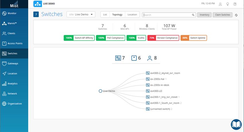
Figure 8: The Switches Page Shows the EX Series Switch
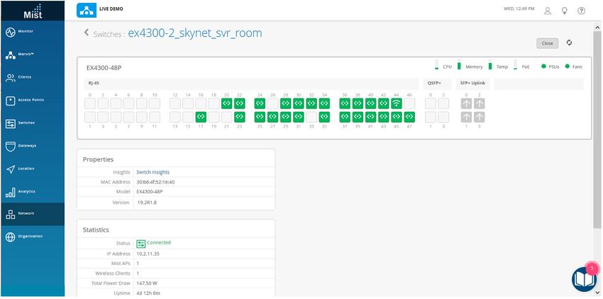
3. Next, select Switches from the menu on the left and click a switch name to display the access points
connected to that switch.
• Hover your mouse cursor over a switch in the list to see summary details of the switch, or click it to
expose attached devices.
• Click the name of the switch (which appears above the list) to open a page where you can dig in to
switch details, including various metrics and properties. Scroll down to see the Junos configuration
for that specific switch.
Figure 9: Switch Details in The Switches Page16
Troubleshooting
Confirm your connection from the switch to the Juniper Mist cloud by running the Junos OS command
below.
user@host> show system connections | grep 2200
The command output shows the switch connection to the Juniper Mist cloud. It includes the IP address
of the management interface on the switch, the destination IP address of the Juniper Mist cloud, and the
connection result.
tcp4 0 0 10.10.70.89.63208 .2200 ESTABLISHED
If there is no ACK of the SYN packet, chances are that outbound packets over TCP port 2200 are being
blocked by the firewall, and this issue needs to be resolved before the switch can appear in the Juniper
Mist portal under Organization > Inventory > Switches.
Day 1: Use a Template-Based Configuration with
Device and Port Profile
IN THIS SECTION
Configuration Templates | 18
Case 1: Organization-Level Switch Settings | 20
Case 2: Network-Level Settings | 21
Case 3: Individual Switch Administration | 22
Dynamic Port Profiles | 24
Configure Network Access | 25
Add a Port Profile | 27
Configure a Dynamic Port | 30
Associate Ports | 33
Virtual Chassis | 34
Design Considerations for Virtual Chassis | 3517 Virtual Chassis on EX2300 Switches with the Juniper Mist Cloud | 37 Virtual Chassis on EX3400 and EX4300 Switches with the Juniper Mist Cloud | 39
18

Configuration Templates
19

A key feature of switch management through the Juniper Mist cloud architecture is the ability to use
configuration templates and a hierarchical model to group the switches and make bulk updates. Templates
provide uniformity and convenience, while the hierarchy (organization, network, and switch) provides both
scale and granularity.

You can create a template configuration and then apply those settings to all the devices in a given group.
When a conflict occurs, for example when there are settings at both the network and organizational levels
that apply to the same device, the more narrow settings (in this case, network) override the broader settings
defined at the organization level.

Figure 10: The Claim Switches Page

Individual switches, at the bottom of the hierarchy, can inherit all or part of the configuration defined at
the organization level, and again at the network level. Of course, individual switches can also have their
own unique configurations.
20

You can include individual CLI commands at any level of the hierarchy. These commands are then appended
to all the switches in that group on an AND basis – that is, individual CLI settings are appended to the
existing configuration (existing setting are not replaced).

Table 2: Hierarchical Templates

 Organization Level                        Network Level                           Switch Level

 • Networks (VLANS)                        • Overrides settings defined at the     • Includes settings such as device hostname, IP
                                               organization level                      address, and role

 • Port profiles and configuration rules   • Can include network-specific RADIUS   • Overrides settings defined in a switch
                                               or NTP server settings (or both)        template at the organization or network level,
                                                                                       such as an NTP server or a RADIUS server

 • Switch matching rules                   • Additional CLI commands               • Additional CLI commands

 • RADIUS server configuration             -                                       -

 • NTP server configuration                -                                       -

 • Additional CLI commands                 -                                       -

There is a lot of flexibility in how you can design templates and use them at different levels of the hierarchy.
To illustrate this, we’ll look at four use cases to show the interplay between configuration settings made
at different levels of the hierarchy.

For each of the use cases below, start by clicking Organization > Switch Templates in the main Juniper
Mist menu. If you don’t see that option, you need a network administrator account before you can proceed.

Case 1: Organization-Level Switch Settings

Enterprise A has multiple sites, all of which use the same VLANs and ports. However, at the switch level,
different switch models are deployed, and the switches don’t all have the same exact port configurations
or the same number of ports.
21 Figure 11: Organization-Level Switch Template Template Solution • Start with an organizational-level switch template. • Configure the VLANs and ports, which will then be applied uniformly to all switches in each network that is included in the organization. • Use the Port Configuration Rules feature in the organization template to create different port configuration rules for each of the different switch models found in the organization. • Assign the organization template to all sites. Any switches, now or in the future, that are added to one of the sites will inherit the VLAN settings, and the port rules, according to the switch model. Case 2: Network-Level Settings Enterprise B has multiple sites, all of which use the same VLANs, ports, and port configurations. However, one network has a RADIUS server that uses 802.1X authentication (and so is different from what is configured at the organization level).
22

Figure 12: Network-Level Template

Template Solution

• Start with a network-level switch template.

• Because this network uses a unique RADIUS server (that is, one that is different than the one defined
  at the organization level), we will override that configuration with the setting specified here.

Case 3: Individual Switch Administration

Enterprise C has multiple sites, each of which is managed by a local IT team. In other words, each team
wants to be able to configure the switches under their control, without inheriting any setting from the
network or organization level hierarchies. As such, if a given switch has a specific VLAN or RADIUS server
(such as 10.10.10.10) they can add it here.
23

Figure 13: Switch-Level Template
24

Dynamic Port Profiles
25

When you connect a device to a Juniper switch interface, the port can be automatically provisioned with
device-appropriate port properties and network access. For example, if you connect a Juniper access point
to a switch, the port will be automatically set as a trunk interface and added to selected VLANs. Likewise,
if you connect a remote camera to the switch, that port can be automatically configured as an access
interface and assigned a different VLAN.

This feature is called dynamic ports, and it work by leveraging the client device’s Link Layer Discovery
Protocol (LLDP) properties to automatically associate pre-configured port and network settings, and
applying those settings to the interface. LLDP data is assigned by the device manufacturer and is typically
hard coded in the device. The following LLDP properties are supported for use with dynamic port profiles:

• System name

• LLDP chassis ID

• RADIUS user name

In the procedures that follow, you’ll set up a dynamic port profile for interface ge-0/0/2. To do so, you’ll
create one or more network objects (these are used to define network access on the basis of VLAN IDs
that are already in use on the network), and you’ll create at least one port profile (these include properties
such as trunk or access port, untagged or native VLAN, and VoIP). Then you’ll associate the port profile
with a network object, and, in the dynamic port profile, associate the device LLDP with one of the
port/network profiles.

After connecting a Juniper access point, the port configuration will change from the previous default,
restricted_device, to the dynamically assigned mist-ap profile. Figure 14 on page 25 shows what this looks
like in the Juniper Mist dashboard (the Switches page).

Figure 14: Dynamically Assigned Port Profile

Note that to set up dynamic ports, the switch needs to be managed through the Juniper Mist portal. You
will also need to know the LLDP properties of one or more client devices to make these configurations on
your switch.
26

Configure Network Access

To protect against unknown or rouge devices being added to the network, Juniper recommends that you
create a restricted network, with limited access, that can be applied by default to unknown devices. We’ll
do that in the steps below, but at the same time we recommend that you create a few other network
objects based on different VLAN IDs from you network so you have a selection to choose from when later
creating the port profiles.

Figure 15: Restricted Network

To add a network to the configuration:

1. In the Juniper Mist portal, click Switches in the menu on the left and then click a switch name to open
   the properties dashboard for that device (if you are looking at the Topology view, you may need to drill
   down to find the switch).

2. Scroll down the page that appears to find the Networks configuration box, and then click Add Network.

3. Give the Network a name, which will be used to identify it in the list when creating the port profile.

4. Specify a VLAN ID that includes (or excludes) the network access you want for this object.

5. When you’re done, click the check mark to add it to your Network list.
27

Add a Port Profile
28

Port Profiles is where you configure the settings that will be automatically applied to devices that match
the LLDP information when they are connected an interface.

Figure 16 on page 28 shows two port completed profile configurations. The one the left shows the default
settings that are applied to unknown devices. The one on the right shows a typical configuration of Juniper
access points. Each port profile provides different levels of network access, as determined by which
network(s) you attach.

Figure 16: Port Profiles
29

To add a port profile to the configuration:

1. Under Port Profiles, click Add Profile.

2. Give the Profile a name, which will be used to identify it in the list when defining the dynamic port
   configuration.
30

3. Fill out the rest of the fields to create a template of the properties you want. In particular, choose
   whether the interface should be Trunk or Access. For Juniper access points, use Trunk.

4. Assign a network to the profile.

5. When you’re done click the check mark to add this network object to the list of port profiles.

Configure a Dynamic Port

To configure a dynamic port, you define a LLDP string and match rules in the dynamic port profile. These
rules are evaluated so that the first match to occur is applied. Wild cards are supported. To get the level
of differentiation you may need to identify a given device, you can specify an offset for the evaluation
start point, or specify a particular LLDP segment to use for the match.

Figure 17 on page 31 shows an example of the configurations. Whenever a Juniper access point is connected
to a specified port on the switch, the port is automatically provisioned as a trunk port, and the device
granted default network access.
31

Figure 17: Dynamic Port

The following steps use the Chassis ID for a Juniper access point, such as can be found by running the
show lldp neighbors command from the Junos OS CLI:

  user@device> show lldp neighbors
  Local Interface         Parent Interface        Chassis Id               Port info
  System Name
  ge-0/0/2                -                       00:00:5E:00:53:e1         ETH0
  AP43-2
  ge-1/0/4                -                       00:00:5E:00:53:da        ETH0
  AP-41-EX-switch

1. On the same page in the Juniper Mist portal that we have been working, scroll to Dynamic Port
   Configuration.

2. Click Add Rule to open the configuration (a name will be automatically given to the new rule when you
   click the check mark to save it).

3. Select LLDP Chassis ID from the drop down.
32

4. In the If text starts with field, type the first three octets of the Chassis ID:

      00:00:5E

5. From the Apply Configuration Profile drop-down list, choose the configuration profile that you want
   to automatically associate with devices that match this profile.

6. When you’re done click the check mark to add this profile dynamic port configurations.
33
Associate Ports
The last thing to do is to associate the profile you just created with one or more ports on the switch so
that only if a recognized device is connected to an appropriate port is the profile be applied.
Figure 18: Port Configuration
To add a port configuration:
1. Under Port Configuration, click Add Port Range. These ports can be listed individually, or given as a
range.
2. Use the interface name to specify the port, or range of ports, that you want this rule to cover (the
format for individual, sequence, and a range are shown here):
ge-0/0/2
ge-0/0/1,ge-0/0/3,ge-0/0/5,ge-0/0/7,ge-0/0/9
ge-0/0/1-12
3. From the Apply Configuration Profile drop-down list, choose the configuration profile that you want
to associate with this port range.34 4. When you’re done click the check mark to add the port definition to the list of port ranges. 5. To see the port profile status after the dynamic profile is assigned, click Switches the in the dashboard menu and then the switch name that you just configured. 6. Click the port you configured (ge-0/0/2 in our example), to view the port Statistics and Port Configuration. An example is shown in Figure 14 on page 25. 7. (Optional) Click Monitor > Service Levels the in the dashboard menu and then scroll down the list of Switch Events, to see the Dynamic Port Profile Assigned event for the changes you just made. With the procedures above completed, whenever a new device is connected to a port on the switch that is covered by one of the dynamic port profiles, the profile will read the device’s LLDP, and if it finds a match, automatically apply the associated port properties and network access to the port. Virtual Chassis We recommend using Virtual Chassis (VC). With VC, you can combine multiple EX Series Switches so they act as a single logical device with in the Juniper Mist cloud (a Wired Assurance subscription is required for each physical EX Series Switch in your VC deployment). Using VC eliminates the risk of loops, the need for legacy redundancy protocols such as spanning tree and VRRP, and the time required for individual device management. In core/distribution deployments, you can connect to the Virtual Chassis using link aggregation group (LAG) uplinks, which then has the additional benefit of the member switches providing device-level redundancy for the link in case of device failure. Figure 19: A Typical Virtual Chassis Setup A Virtual Chassis can include from two to ten switches, with each member switch having however many ports. Such a physical configuration can provide better resilience in case one member switch goes down;
35

there are simply more surviving switches available to take up the redistributed load. The trade-off, though,
is that those switches require both space and power.

Virtual Chassis for the Juniper Mist cloud is supported for the switches shown in Table 3 on page 35. The
switch model is accompanied by the maximum number of members allowed in the Virtual Chassis.

Table 3: Cloud-Ready EX Series Switches

 Switch                              Maximum Members

 EX2300                              4

 EX3400                              10

 EX4300                              10

 EX4600                              10

 EX4650                              2

Design Considerations for Virtual Chassis

We recommend that you physically distribute your Juniper access points across a floor in the network
operations center (NOC) so that they connect to multiple switches in a virtual stack. Doing so provides
better redundancy and is a more robust design for handling power-supply-related hardware failure.
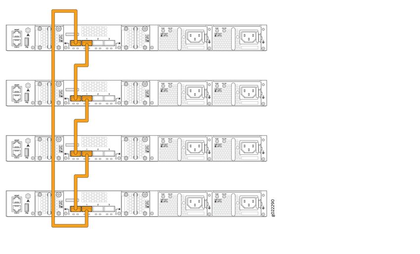
36

Figure 20: Virtual Chassis Setup in a NOC

For example, let’s say you want to deploy a solution that includes 96 ports. The two main options for doing
so are:

• Use two EX4300-48P switches, with one switch serving as the primary and one as backup. The advantages
  here are a compact footprint and cost effectiveness. The main disadvantage is that the loss of one switch
  can impact 50 percent of your users.

• Use four EX4300-24P switches, with one switch serving as the primary, one as backup, and two switches
  serving as line cards. The advantages here are higher availability (the loss of one switch only affects 25
  percent of users), and the fact that uplinks are not affected by a switch failure (provided that the failed
  switch did not include any uplinks). The main disadvantage is that you need more space, power, and cost
  to support the equipment.

Regardless of the options you go with, if you do plan to leverage one or more Virtual Chassis in your
deployment, we recommend that you configure the primary and backup switches in the Virtual Chassis
so that they are in different physical locations in the NOC. The member devices of the Virtual Chassis
should be likewise distributed so that no more than half are dependent on the same power supply or other
single point of failure, and they should be evenly spaced by a member hop in the Virtual Chassis.
37

Virtual Chassis on EX2300 Switches with the Juniper Mist Cloud

Switches in a Virtual Chassis must all be the same model and running the same version of Junos OS, which
must also be compatible with the Juniper Mist cloud architecture. You will need physical access to the
switches for cabling, and management access to both the CLI and Juniper Mist portal.

Figure 21: Virtual Chassis for EX2300
38

In the process described below, you start with a switch that has already been provisioned and is available
from the Juniper Mist portal. Then you log in to the switch using the Juniper Mist portal and configure its
Virtual Chassis interfaces. From there, you make the physical connection from that switch to the next one
in the Virtual Chassis group, propagate the relevant settings, and repeat until all the Virtual Chassis members
are connected. The last step is then to synchronize the Virtual Chassis configuration across member
switches.

Figure 22: Virtual Chassis Connections for EX2300

1. Power on each EX Series switch, but do not connect any Ethernet or Virtual Chassis cables yet.

2. Physically connect the switch to the Internet using either a management or revenue port. The switch
   will automatically receive ZTP updates from the cloud, including the DNS settings it will need. In the
   Juniper Mist portal, the switch should be visible, and with a green status.

3. Access the switch from the Juniper Mist portal using the Junos OS CLI shell, and run the following
   commands to enable Virtual Chassis ports on the switch.

     request virtual-chassis vc-port set pic-slot 1 port 0
     request virtual-chassis vc-port set pic-slot 1 port 1

4. Verify that the ports were successfully configured by running this command.

     show virtual-chassis vc-port

5. Back at the switches, connect a Virtual Chassis cable from the ports you just enabled to the next switch
   and confirm that the LEDs on the Virtual Chassis ports are active.
39
6. From the Junos OS CLI shell, run the following command to confirm that the newly added switch is
present.
show virtual-chassis
7. Repeat Step 2 through step 7 until all switches have been added to Virtual Chassis and then connect
the Virtual Chassis port redundancy cable.
When you are done, the switch will be added to the Juniper Mist cloud, and you can see it from the Switches
page as shown in Figure 13 on page 23.
Virtual Chassis on EX3400 and EX4300 Switches with the Juniper Mist
Cloud
Switches in a Virtual Chassis must all be Juniper Mist cloud ready. You will need physical access to the
switches for cabling, and management access to both the Junos OS CLI and Juniper Mist portal.
Figure 23: Virtual Chassis for EX4300
Note that the second switch in the Virtual Chassis is automatically assigned the backup role, and its LED
will blink when connected. All remaining switches automatically assume line-card roles, and their MST
LEDs will remain dark.40
Figure 24: Virtual Chassis for EX3400
In the process described below, you start with a switch that is available from the Juniper Mist portal. Then
you log in to the switch using the Juniper Mist portal and configure its Virtual Chassis interfaces. From
there, you make the physical connection from that switch to the next one in the Virtual Chassis group,
propagate the relevant settings, and repeat until all the Virtual Chassis members are connected.
1. Power on each EX Switch, but do not connect any Ethernet or Virtual Chassis cables yet. Wait until
you see the MST LED is lit and not blinking on any of the switches.
2. Physically connect the switch to the Internet using either a management or revenue port. The switch
will automatically receive ZTP updates from the cloud, including the Virtual Chassis configuration. In
the Juniper Mist portal, the switch should be visible, and with a green status.
3. Access the switch from the Juniper Mist portal using the CLI shell, and run the following commands to
verify that the Virtual Chassis ports were successfully configured (all the switches in the Virtual Chassis
should be listed in the results).
show virtual-chassis
4. Back at the switches, connect a Virtual Chassis cable from to the next switch and confirm that the LED
on the Virtual Chassis ports are active.
5. Repeat Step 2 through step 4 until all switches have been added to Virtual Chassis and then connect
the Virtual Chassis port redundancy cable.41
Figure 25: Virtual Chassis for EX4300
When you are finished, the Virtual Chassis will be provisioned for the Juniper Mist cloud and the details
of the EX Series swtich cluster will be visible in the Juniper Mist portal.
root@EX3400-VC> show virtual-chassis
Virtual Chassis ID: c3d2.5525.cd30
Virtual Chassis Mode: Enabled
Mstr Mixed Route Neighbor List
Member ID Status Serial No Model prio Role Mode
Mode ID Interface
0 (FPC 0) Prsnt NW3619450867 ex3400-24p 128 Master* N VC
1 vcp-255/1/0
1 vcp-255/1/1
1 (FPC 1) Prsnt NW3619451026 ex3400-24p 128 Backup N VC
0 vcp-255/1/0
0 vcp-255/1/1
Member ID for next new member: 2 (FPC 2)
RELATED DOCUMENTATION
Juniper Virtual Chassis Best Practices Guide42
Day 2: Wired User Service Level Expectations, Switch
Events, and Marvis Actions
The Juniper AI-driven network includes Wired Assurance Service, which provides automated operations
and service levels to Juniper enterprise access switching using the Juniper Mist cloud; Health Statistics
for Wired Switches, which provides visibility into EX Series switch details and allows you to find missing
VLANs, identify outages, and get alerts on critical metrics; and Marvis Actions, which is a framework for
self-driving networks that converts AI-driven insight into actionable tasks.
Use Marvis to list wired clients connected to the network and troubleshoot any corresponding issues that
it identifies, such as speed mismatches, missing VLANs, switch health, and anomaly detection. Marvis helps
identify the root cause of issues across various IT domains (WLAN, LAN, WAN, and security), and
automatically resolve issues within its purview.
Manual EX Series Switch Configurations
IN THIS SECTION
Requirements | 43
Overview | 43
Set Up the EX Series Switch | 44
Configure the Guest and Employee Networks | 45
Enable PoE+ on the Interfaces | 48
Enable Junos OS Link Layer Discovery Protocol | 50
Enable the Switch to Receive DHCP or BOOTP Requests | 51
Enable 802.1x Authentication on the Switch Ports | 56
Manage Logs in EX Series Switches | 57
(Optional) Automate Switch Port Provisioning | 5843 Requirements All the features you need to set up interoperability between Juniper access points with EX Series switches are available in Junos OS Release 18.4R2.7 and later. The procedures are the same for any Juniper EX2300, EX3400 or EX4300 Ethernet Switch, and any Juniper access points (AP43, AP41, AP 21, and AP61). Overview To manually connect Juniper access points to an EX Series switch, start by configuring the switch and then move to the Juniper Mist portal on the cloud to finish the connection details. Once connected, you can also SSH back to the switch from the Juniper Mist portal to make any additional configuration settings you might have. Figure 26: Switch Connections
44

Set Up the EX Series Switch

Before You Begin

Note that it might be necessary to configure your firewall so that the switch can receive the traffic from
the Juniper Mist cloud over TCP port 2200. If so, please see your firewall documentation for those details.

PoE must be enabled on the relevant interfaces of the EX Series switch.

In addition, when making the physical connections, pay attention to the LED status lights on the Juniper
access points to see whether the connection is good. The LEDs use a blink pattern to signal connection
errors in the event the connection to the cloud fails. A steady green light indicates the connection succeeded,
and a steady red light indicates failure. Two red lights mean the device is booting up. For information on
all lights and blink patterns, see What is the LED telling me?

Configure a Hostname and Password on the EX Series Switch

Step-by-Step Procedure
The first task is to configure some system settings on the EX Series switch, including a hostname and
password.

1. Log in to the device CLI and type configure to start configuration mode, which allows you to edit the
   configuration.

2. In the CLI, enter the following commands (note that you are prompted to create a password as part of
   the second command).

   set system host-name Switch-1
   set system root-authentication plain-text-password

3. Next, add a DNS server so the switch can resolve the IP addresses obtained from the Juniper Mist
   portal.

   set system name-server ip-address

4. Configure your time zone and add an NTP server to the switch.

   set system time-zone UTC
   set system ntp server ip-address

5. For any EX Series switches that are acting as a DHCP client, disallow automatic software downloads.
45

   delete chassis auto-image-upgrade

6. To allow remote administration of the EX switch from the Juniper Mist portal, you need to enable root
   login over SSH.

   set system services ssh root-login allow

Configure the Guest and Employee Networks

On EX Series switches, you can configure a port interface as either a Layer 2 access port, a Layer 2 trunk
port, or a Layer 3 interface port. A Layer 2 trunk port is typically used when there is traffic from multiple
VLANs connecting to it. To differentiate the separate VLAN flows, packets entering the port are tagged
with a VLAN identifier (as defined in IEEE 802.1Q) of your choice.

You can connect the Juniper access points to a tagged port or untagged port configured for native VLAN.
This NCE uses untagged (also known as native), because Juniper access points boot on untagged VLANs
by default.

To protect the LAN against broadcast storms, we’ll also enable storm control on the interfaces (briefly,
storm control is a feature that prevents broadcast storms by automatically dropping packets when
traffic-levels exceed a set limit).

Step-by-Step Procedure
1. Configure the VLAN IDs for the management, guest, and employee networks using the following VLAN
   IDs: VLAN 180, VLAN 188, and VLAN 189, respectively.

     set vlans management vlan-id 180
     set vlans guest vlan-id 188
     set vlans employee vlan-id 189

2. To locally route between VLANs or subnets on the local switch, you need integrated routing and bridging
   (IRB) interfaces. We create these here, and also assign each IRB an IP address for connecting to the
   Juniper Mist portal.

     set interfaces irb unit 180 family inet address 192.168.180.1/24
     set interfaces irb unit 188 family inet address 192.168.188.1/24
     set interfaces irb unit 189 family inet address 192.168.189.1/24

3. Next you need to attach each of the IRBs that you just created to its respective VLAN.
46
set vlans management l3-interface irb.180
set vlans guest l3-interface irb.188
set vlans employee l3-interface irb.189
4. Associate the physical interfaces with their respective VLANs, and apply storm control. For the guest
network, this example uses ge-0/0/0 configured as an access interface. The employee network uses
ge-0/0/2, also as an access interface.
The interface that the Juniper access points will connect to is ge-0/0/1, which is configured as a trunk
interface. Set the management VLAN as a native (untagged) interface because an access point boots
on an untagged VLAN by default.
set interfaces ge-0/0/0 unit 0 family ethernet-switching interface-mode access
set interfaces ge-0/0/0 unit 0 family ethernet-switching vlan members guest
set interfaces ge-0/0/0 unit 0 family ethernet-switching storm-control default
set interfaces ge-0/0/1 native-vlan-id 180
set interfaces ge-0/0/1 unit 0 family ethernet-switching interface-mode trunk
set interfaces ge-0/0/1 unit 0 family ethernet-switching vlan members employee
set interfaces ge-0/0/1 unit 0 family ethernet-switching vlan members guest
set interfaces ge-0/0/1 unit 0 family ethernet-switching vlan members management
set interfaces ge-0/0/1 unit 0 family ethernet-switching storm-control default
set interfaces ge-0/0/2 unit 0 family ethernet-switching interface-mode access
set interfaces ge-0/0/2 unit 0 family ethernet-switching vlan members employee
set interfaces ge-0/0/2 unit 0 family ethernet-switching storm-control default
5. Create a default storm control profile to support the storm-control settings in the previous step.
set forwarding-options storm-control-profiles default all
set forwarding-options storm-control-profiles default action-shutdown
6. Add a default gateway to the switch. Use the IP address of your next-hop router.
set routing-options static route 0.0.0.0/0 next-hop gateway-ip
7. To show your wired clients in the Juniper Mist portal, you need to enable dhcp-security on the IRB
interfaces.
set vlans employee forwarding-options dhcp-security group trusted-group overrides
trusted47
set vlans employee forwarding-options dhcp-security group untrusted-group
overrides untrusted
set vlans guest forwarding-options dhcp-security group trusted-group overrides
trusted
set vlans guest forwarding-options dhcp-security group untrusted-group overrides
untrusted
set vlans management forwarding-options dhcp-security group trusted-group
overrides trusted
set vlans management forwarding-options dhcp-security group untrusted-group
overrides untrusted
8. Check your settings for validity by running the Junos OS commit check command, or run the following
show commands to display the configuration as entered (the vlan information included below appears
only after the configuration has been committed).
show interfaces ge-0/0/1
user@Switch-1# show interfaces ge-0/0/1
native-vlan-id 180;
unit 0 {
family ethernet-switching {
interface-mode trunk;
vlan {
members [ employee guest management ];
}
storm-control default;
run show vlans
user@Switch-1# run show vlans
Routing instance VLAN name Tag Interfaces
default-switch employee 189
ge-0/0/1.0
ge-0/0/2.0
default-switch guest 188
ge-0/0/0.0
ge-0/0/1.0
default-switch management 180
ge-0/0/1.048
default-switch management NA
Enable PoE+ on the Interfaces
Step-by-Step Procedure
The next task is to enable PoE+ on the interfaces. Start by checking what version of the controller software
the switch is running. (A more recent version might be on the device as part of a Junos OS upgrade, and
if so, you should upgrade the controller software.) You can find instructions for doing the upgrade in this
document: Upgrading the PoE Controller Software.
1. Find what version of the controller software the switch is running.
run show poe controller
user@Switch-1#run show poe controller
Controller Maximum Power Guard Management Status Lldp
index power consumption band Priority
0** 146W 0.00W 0W Class AT_MODE Disabled
**New PoE software upgrade available.
Use 'request system firmware upgrade poe fpc-slot
This procedure will take around 10 minutes (recommended to be performed during
maintenance)
To stay well within the capacity of the power supply (single or dual) provisioned on most EX Series
switches, we recommend that you budget 75 percent or less of the switch ports for (physically)
connecting 802.11at PoE capable Juniper access points.
2. Enable PoE+ on the switch interfaces intended for Juniper access point connections.
set poe interface all
set poe interface ge-0/0/1 priority high
set poe interface all telemetries
3. Verify your configuration settings (the details below appear only after the configuration has been
committed).49
run show poe interface ge-0/0/1
user@Switch-1#run show poe interface ge-0/0/1
PoE interface status:
PoE interface : ge-0/0/1
Administrative status : Enabled
Operational status : ON
Operational status detail : IEEE PD Detected
FourPair status : Disabled
Power limit on the interface : 19.5W (L)
Priority : Low
Power consumed : 7.8W
Class of power device : 4
PoE Mode : 802.3at
(L) LLDP-negotiated value on the port.
4. Enable PoE power monitoring on the switch to view real-time statistics including power consumption,
and to support port-level telemetry. Do this for all switch ports, or at least for those connecting to a
Juniper access point.
set poe interface all telemetries interval 10
5. Run the following commands to view PoE statistics (the details shown below appear only after the
configuration has been committed).
run show poe interface
user@Switch-1#run show poe interface
Interface Admin Oper Pair/Mode Max Priority Power
Class
status status status power consumption
ge-0/0/0 Enabled OFF 2P/AT 15.4W Low 0.0W
not-applicable
ge-0/0/1 Enabled OFF 2P/AT 15.4W Low 0.0W
not-applicable
ge-0/0/2 Enabled ON 2P/AT 19.5W(L) High 11.2W
4
ge-0/0/3 Enabled ON 2P/AT 25.5W(L) High 11.0W
4
ge-0/0/4 Enabled OFF 2P/AT 15.4W Low 0.0W
not-applicable
ge-0/0/5 Enabled OFF 2P/AT 15.4W High 0.0W
not-applicable50
ge-0/0/6 Enabled OFF 2P/AT 15.4W Low 0.0W
not-applicable
ge-0/0/7 Enabled OFF 2P/AT 15.4W Low 0.0W
not-applicable
ge-0/0/8 Enabled OFF 2P/AT 15.4W Low 0.0W
not-applicable
ge-0/0/9 Enabled OFF 2P/AT 15.4W Low 0.0W
not-applicable
ge-0/0/10 Enabled OFF 2P/AT 15.4W Low 0.0W
not-applicable
ge-0/0/11 Enabled OFF 2P/AT 15.4W Low 0.0W
not-applicable
(L) LLDP-negotiated value on the port.
Enable Junos OS Link Layer Discovery Protocol
Step-by-Step Procedure
Have the switch send Junos OS Link Layer Discovery Protocol (LLDP) information to the Juniper Mist
cloud. Although LLDP is enabled by default on all interfaces on the switch, you need to configure it as
shown here so it works with the Juniper Mist portal. (LLDP, as described in the IEEE 802.1AB specification,
is a standards-based method of exchanging device capabilities.)
1. Enter the following commands to configure LLDP (using an IP address appropriate for your network).
set protocols lldp interface all
set protocols lldp-med interface all
set protocols lldp port-id-subtype interface-name
set protocols lldp management-address 192.168.180.1
2. View the LLDP statistics (the details shown below appear only after the configuration has been
committed).
run show lldp neighbors
user@Switch-1# run show lldp neighbors
Local Interface Parent Interface Chassis Id Port info
System Name
ge-0/0/2 - 00:00:5E:00:53:00 ETH051
3. Query the Junos OS switching table to see if the Juniper access points show up in the MAC table. In
the example output, the management VLAN appears, which confirms that they do.
run show ethernet-switching table
user@Switch-1# run show ethernet-switching table
MAC flags (S - static MAC, D - dynamic MAC, L - locally learned, P - Persistent
static, C - Control MAC
SE - statistics enabled, NM - non configured MAC, R - remote PE MAC,
O - ovsdb MAC)
Ethernet switching table : 1 entries, 1 learned
Routing instance : default-switch
Vlan MAC MAC Age Logical
NH RTR
name address flags interface
Index I
management 00:00:5E:00:53:00 D - ge-0/0/1.0
0 0
Enable the Switch to Receive DHCP or BOOTP Requests
Step-by-Step Procedure
You enable the switch to receive DHCP or BOOTP requests so it can receive broadcast messages, sent
from clients and associated to the Juniper access points, and then relay these requests to a DHCP or
BOOTP server. This is especially important for wireless clients so they can reach a given remote DHCP or
BOOTP server even though neither the access point nor clients have Layer 2 adjacency with the DHCP
server.
1. Enable BOOTP requests on the switch, by entering the following command.
set forwarding-options helpers bootp server IP-address
(You must explicitly type “bootp” for the command to appear, that is, you can’t just use the tab or space
key.)
2. You can also configure the switch to act as a DHCP server. Doing so is useful for sandbox deployments,
but in a production environment, we recommend that you use an external DHCP server (that is, not52
DHCP on the switch). The following commands create DHCP pools for the guest, employee, and
management VLANs, and also for any Juniper access points and associated clients.
set access address-assignment pool employee family inet network 192.168.188.0/24
set access address-assignment pool employee family inet range range1 low
192.168.188.10
set access address-assignment pool employee family inet range range1 high
192.168.188.50
set access address-assignment pool employee family inet dhcp-attributes
name-server 8.8.8.8
set access address-assignment pool employee family inet dhcp-attributes router
192.168.188.1
set access address-assignment pool guest family inet network 192.168.189.0/24
set access address-assignment pool guest family inet range range1 low
192.168.189.10
set access address-assignment pool guest family inet range range1 high
192.168.189.50
set access address-assignment pool guest family inet dhcp-attributes name-server
8.8.8.8
set access address-assignment pool guest family inet dhcp-attributes router
192.168.189.1
set access address-assignment pool management family inet network 192.168.180.0/24
set access address-assignment pool management family inet range range1 low
192.168.180.10
set access address-assignment pool management family inet range range1 high
192.168.180.50
set access address-assignment pool management family inet dhcp-attributes
name-server 8.8.8.8
set access address-assignment pool management family inet dhcp-attributes router
192.168.180.1
set system services dhcp-local-server group guest interface irb.188
set system services dhcp-local-server group employee interface irb.189
set system services dhcp-local-server group management interface irb.180
3. (Optional) Configure a proxy URL using DHCP option 43. This step is provided to support the case
where you have Juniper access points that need to connect to the EX Series switch using a proxy server.
The first set of commands shows how to add the IP address of the proxy in plain text for the guest,
employee, and management VLANs. The second does the same for hex addresses (you only need to
run one). See Proxy URL Configuration via DHCP Option 43 with Microsoft Windows Server for more
information.53
edit access address-assignment pool employee
set family inet network 192.168.188.0/24 dhcp-attributes option 43 string
ip:20.0.0.10,20.0.0.11
edit access address-assignment pool guest
set family inet network 192.168.189.0/24 dhcp-attributes option 43 string
ip:20.0.0.10,20.0.0.11
edit access address-assignment pool management
set family inet network 192.168.180.0/24 dhcp-attributes option 43 string
ip:20.0.0.10,20.0.0.11
or
edit access address-assignment pool employee
set family inet network 192.168.188.0/24 dhcp-attributes option 43 hex-string
69703A32302E302E302E31302C32302E302E302E3131
edit access address-assignment pool guest
set family inet network 192.168.189.0/24 dhcp-attributes option 43 hex-string
69703A32302E302E302E31302C32302E302E302E3131
edit access address-assignment pool management
set family inet network 192.168.180.0/24 dhcp-attributes option 43 hex-string
69703A32302E302E302E31302C32302E302E302E3131
Verify
Step-by-Step Procedure
Confirm your settings by running show commands at the different levels of the hierarchy to display the
configuration as entered. Confirm the validity by running the Junos OS commit check command (you need
to actually commit the configuration to see the actual dhcp server binding).
1. View the configurations you entered.
show access address-assignment54
user@Switch-1# show access address-assignment
pool employee {
family inet {
network 192.168.188.0/24;
range range1 {
low 192.168.188.10;
high 192.168.188.50;
}
dhcp-attributes {
name-server {
8.8.8.8;
}
router {
192.168.188.1;
}
}
}
}
pool guest {
family inet {
network 192.168.189.0/24;
range range1 {
low 192.168.189.10;
high 192.168.189.50;
}
dhcp-attributes {
name-server {
8.8.8.8;
}
router {
192.168.189.1;
}
}
}
}
pool management {
family inet {
network 192.168.180.0/24;
range range1 {
low 192.168.180.10;
high 192.168.180.50;
}
dhcp-attributes {
name-server {You can also read