APPMODULE Documentation - Bab Technologie
←
→
Page content transcription
If your browser does not render page correctly, please read the page content below
BAB TECHNOLOGIE GmbH

APPMODULE
Documentation
Version 1.6.1
Type: IP, KNX, EnOcean
Item no.: 10491, 10495, 13501

      Manual version IV
      As of 04/2021
      Date: 30. April 2021

      EN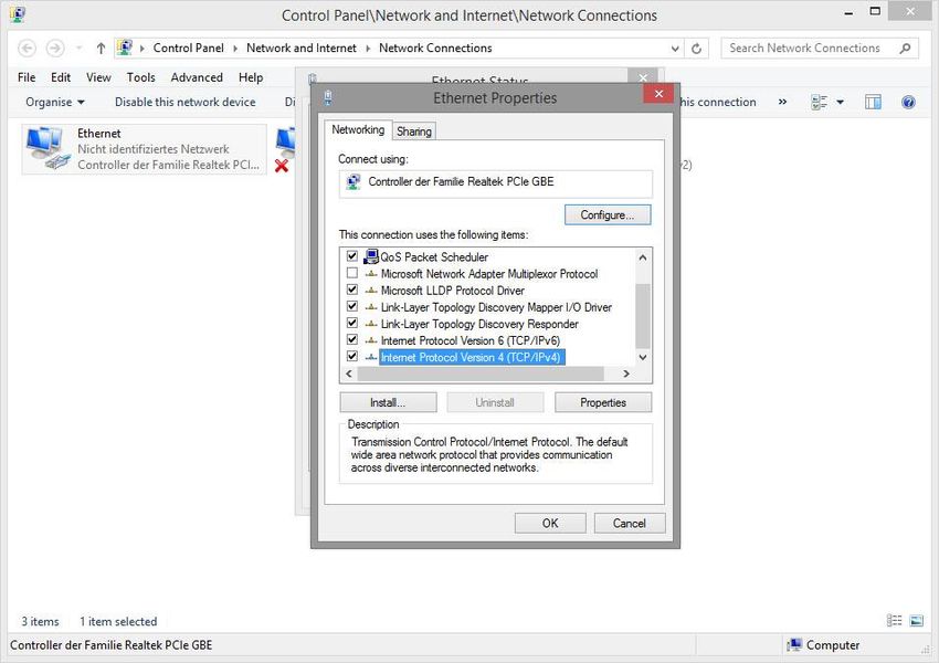
APPMODULE Documentation

                           BAB TECHNOLOGIE GmbH

                           Hörder Burgstr. 18
                           D-44139 Dortmund

                           info@bab-tec.de

                           Tel.: +49 (0) 231 – 476 425 - 30
                           Fax: +49 (0) 231 – 476 425 - 59
                           www.bab-tec.de

2   BAB TECHNOLOGIE GmbH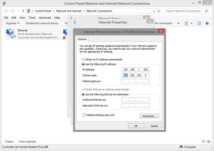
APPMODULE Documentation

TABLE OF CONTENTS
1       APPMODULE .......................................................................................................................................... 6
    1.1         Functional overview...................................................................................................................... 7
    1.2         APPMODULE functional principle ................................................................................................. 7
    1.3         Technical data .............................................................................................................................. 8
    1.4         Scope of delivery and interfaces .................................................................................................. 8
                Factory setting on delivery: .......................................................................................................... 9
                Serial number / Registration key .................................................................................................. 9
    1.5         Updates ......................................................................................................................................... 9
    1.6         Important information on the operating instructions ................................................................. 9
    1.7         Functional safety ........................................................................................................................... 9
2       Assembly ............................................................................................................................................ 10
    2.1     LED status ................................................................................................................................... 11
    2.2     Initial Operation ......................................................................................................................... 12
       2.2.1 Language ............................................................................................................................... 12
       2.2.2 System requirements ............................................................................................................ 12
       2.2.3 Establishing connections....................................................................................................... 12
            Calling up the APPMODULE web interface ............................................................................... 13
            Adjusting the network settings of your computer .................................................................... 14
            Adjusting the network settings of the APPMODULE ................................................................. 17
3       APPMODULE IP................................................................................................................................... 20
    3.1         Connecting the APPMODULE IP to EIBPORT .............................................................................. 20
                Setting up the connection in the APPMODULE ......................................................................... 20
                Setting up the connection in EIBPORT ...................................................................................... 21
    3.2         Using KNX net/IP in the APPMODULE IP .................................................................................... 23
4       APPMODULE KNX............................................................................................................................... 24
    4.1     APPMODULE KNX commissioning .............................................................................................. 24
       4.1.1 KNX configuration ................................................................................................................. 26
       4.1.2 ETS Inside Server .................................................................................................................... 27
5       APPMODULE EnOcean ...................................................................................................................... 28
    5.1     Initial operation of APPMODULE EnOcean ................................................................................ 28
            Technical details about the EnOcean Interface ........................................................................ 28
            EnOcen Kompatibilität............................................................................................................... 28
    5.2     Calling up the EnOcean Editor .................................................................................................. 29
    5.3     Usage of the EnOcean Editor .................................................................................................... 29
       5.3.1 Operating principle EnOcean ............................................................................................... 29
       5.3.2 EnOcean Configuration ......................................................................................................... 30
       5.3.3 EnOcean Settings .................................................................................................................. 32
       5.3.4 EnOcean device teach-in procedure .................................................................................... 33
       5.3.5 Emulating EnOcean devices ................................................................................................. 36
       5.3.6 KNX Addressing ..................................................................................................................... 38
       5.3.7 Configuration example for EnOcean Push-Button (Rocker) ................................................. 39
            APPMODULE as the receiver (actuator) ..................................................................................... 39
    5.4     Delete EnOcean devices ............................................................................................................ 40
6       ETS Project import ............................................................................................................................ 41
                Use ETS project .......................................................................................................................... 41
                Configure Custom Addresses .................................................................................................... 43
7       App Manager ..................................................................................................................................... 44
    7.1     Instance ...................................................................................................................................... 46
       7.1.1 Notation of group addresses ................................................................................................ 46
    7.2     Automatic Smart Home App update ......................................................................................... 47

                                                                                              BAB TECHNOLOGIE GmbH                         3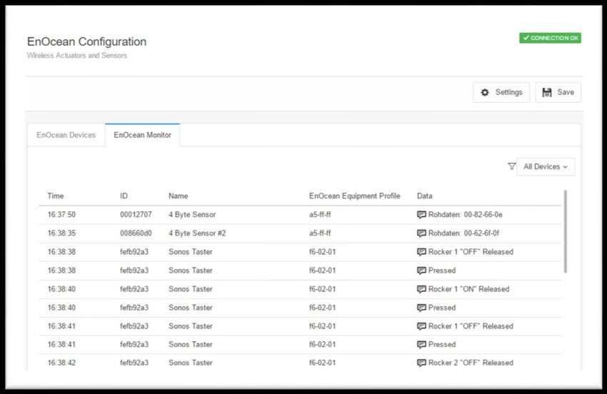
APPMODULE Documentation

8     Configuration .................................................................................................................................... 49
    8.1       Saving the configuration ........................................................................................................... 49
    8.2       General ....................................................................................................................................... 49
    8.3       Network...................................................................................................................................... 50
    8.4       Module ....................................................................................................................................... 51
    8.5       EnOcean Editor .......................................................................................................................... 51
    8.6       User administration .................................................................................................................... 52
              Disable Password Recovery ....................................................................................................... 52
              Smart Screens ............................................................................................................................ 52
    8.7       Remote Servicing ....................................................................................................................... 53
    8.8       Backup the settings ................................................................................................................... 54
              Creating a backup ..................................................................................................................... 54
              Restoring a backup .................................................................................................................... 56
    8.9       System / firmware update ......................................................................................................... 57
              Service ........................................................................................................................................ 57
              Firmware update........................................................................................................................ 57
9     Information ........................................................................................................................................ 59
10    Attachment ........................................................................................................................................ 60

                  4     BAB TECHNOLOGIE GmbH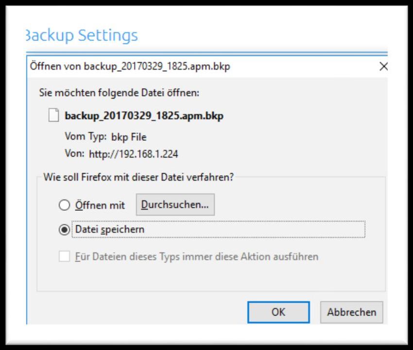
APPMODULE Documentation
List of Figures
Figure 1: APPMODULE KNX ...............................................................................................................................................6
Figure 2: APPMODULE – How it works..............................................................................................................................7
Figure 3: APPMODULE connection diagram.................................................................................................................. 10
Figure 4: APPMODULE start page .................................................................................................................................. 13
Figure 5: Logging in to the web interface .................................................................................................................... 13
Figure 6: "Configuration" menu item ........................................................................................................................... 14
Figure 7: Back to the homepage................................................................................................................................... 14
Figure 8: Windows Network and Sharing Center .......................................................................................................... 14
Figure 9: "Ethernet" status ........................................................................................................................................... 15
Figure 10: Properties of the LAN connection................................................................................................................ 15
Figure 11: TCP/IPv4 properties ..................................................................................................................................... 16
Figure 12: APPMODULE Webinterface .......................................................................................................................... 17
Figure 13: Login dialog ................................................................................................................................................. 17
Figure 14: APPMODULE – Main Menu ........................................................................................................................... 18
Figure 15: APPMODULE Network configuration ........................................................................................................... 19
Figure 16: APPMODULE IP Interface Extension ............................................................................................................. 20
Figure 17: EIBPORT facility coupling job ....................................................................................................................... 21
Figure 18: APPMODULE IP Interface KNXnet/IP ............................................................................................................ 23
Figure 19: KNX configuration ........................................................................................................................................ 24
Figure 20: KNX – Physical Address................................................................................................................................. 25
Figure 21: KNX – assigning a KNXnet/IP tunneling address.......................................................................................... 25
Figure 22: Saving the configuration ............................................................................................................................. 25
Figure 23: ETS Inside Server .......................................................................................................................................... 27
Figure 24: Configuration – EnOcean Editor .................................................................................................................. 29
Figure 25: EnOcean Configuration - Devices ................................................................................................................ 30
Figure 26: EnOcean Configuration - Monitor ............................................................................................................... 31
Figure 27: EnOcean Settings ......................................................................................................................................... 32
Figure 28: Calling up properties ................................................................................................................................... 33
Figure 29: EnOcean Device Configuration ................................................................................................................... 33
Figure 30: Parameters ................................................................................................................................................... 34
Figure 31: Receiving KNX parameters ........................................................................................................................... 39
Figure 32: Devices delete ............................................................................................................................................. 40
Figure 33: Devices delete confirm ................................................................................................................................ 40
Figure 34: ETS Project Import ....................................................................................................................................... 41
Figure 35: Open the "Group Address Selection" window............................................................................................ 41
Figure 36: Group address selection .............................................................................................................................. 42
Figure 37: Assign group address ................................................................................................................................... 42
Figure 38: Configure Custom Addresses....................................................................................................................... 43
Figure 39: APPMODULE Start menu .............................................................................................................................. 44
Figure 40: Install APP ..................................................................................................................................................... 44
Figure 41: Select APP ..................................................................................................................................................... 45
Figure 42: Installation successful .................................................................................................................................. 45
Figure 43: Create Instance ............................................................................................................................................ 46
Figure 44: Instance functions........................................................................................................................................ 46
Figure 45: Update Configuration .................................................................................................................................. 47
Figure 46: Smart Home App Update available ............................................................................................................. 47
Figure 47: Release notes for the update file ................................................................................................................. 48
Figure 48: Update successful ........................................................................................................................................ 48
Figure 49: General configurations ................................................................................................................................ 49
Figure 50: APPMODULE – Network settings .................................................................................................................. 50
Figure 51: User administration ...................................................................................................................................... 52
Figure 52: Remote servicing ......................................................................................................................................... 53
Figure 53: Backup / Restore ......................................................................................................................................... 54
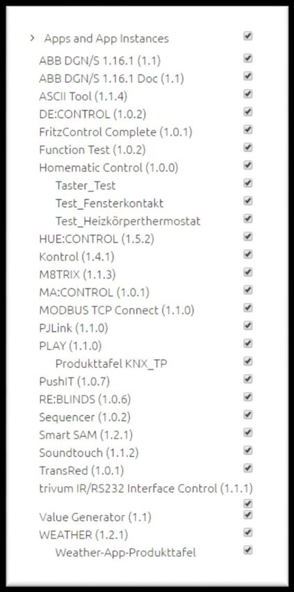
Figure 54: Selecting apps and app instances for backup ............................................................................................. 55
Figure 55: Downloading backup................................................................................................................................... 56
Figure 56: Configuration – System................................................................................................................................ 57
Figure 57: Keep network settings ................................................................................................................................. 58
Figure 58: Perform update ............................................................................................................................................ 58
Figure 59: System Information ...................................................................................................................................... 59
BAB TECHNOLOGIE GmbH 5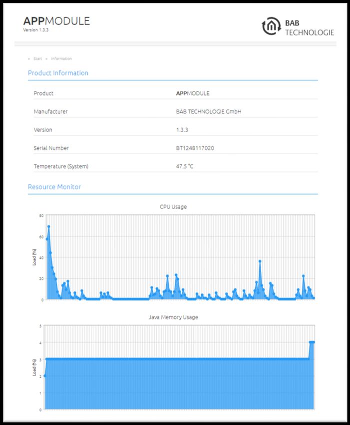
APPMODULE Documentation

1           APPMODULE
Thank you for buying the APPMODULE. The APPMODULE is a unique integration server that you can
customise using the apps from the BAB APPMARKET. This documentation will help to familiarise you with
the product and facilitate implementation.

BAB TECHNOLOGIE GmbH

                                       Figure 1: APPMODULE KNX

Product name:          APPMODULE
Intended use:          Module to run applications
Design:                Modular device (REG)
Item number:           10491 (IP), 10495 (KNX), 13501 (EnOcean)

             6   BAB TECHNOLOGIE GmbH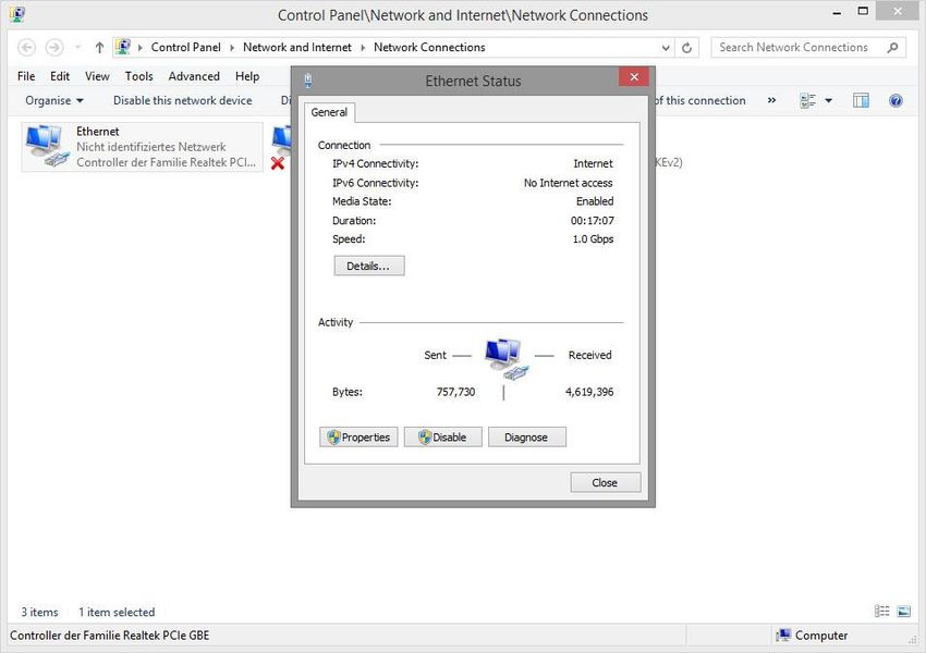
APPMODULE Documentation

1.1          FUNCTIONAL OVERVIEW
The APPMODULE links building automation to third-party applications that otherwise cannot be
controlled by building control. The connection is established with applications that can be installed on
the APPMODULE. You can select your very own combination of apps, and purchase individual apps from
the BAB APPMARKET (https://www.bab-appmarket.de/de/). The APPMODULE is available as “IP” for
EIBPORT, with KNX- or with EnOcean interface.

1.2          APPMODULE FUNCTIONAL PRINCIPLE
On delivery, the APPMODULE contains only the basic software and has no application installed. You can
purchase and download the applications for the APPMODULE in the BAB APPMARKET. For that purpose
you will need an APPMARKET account and an APPMODULE registered in the APPMARKET.
In addition to the download of the purchased applications, there is the option of integration into the
terminal configurator including the purchase of a Smart Home App.

                                    Figure 2: APPMODULE – How it works

You can find the APPMARKET on https://www.bab-appmarket.de/

                                                              BAB TECHNOLOGIE GmbH       7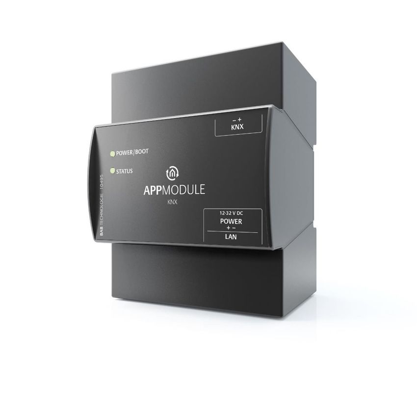
APPMODULE Documentation 1.3 TECHNICAL DATA Article No.: 10491 (IP) | 10495 (KNX) | 13501 (EnOcean) Operating voltage: 12-32V DC Typical power consumption 300 mA at 12V DC Power consumption:
APPMODULE Documentation

FACTORY SETTING ON DELIVERY:

IP address:     192.168.1.224
Username:       "admin"
Password:       "admin"

SERIAL NUMBER / REGISTRATION KEY

The Serial Number (SN) and Registration Key are required to register the APPMODULE. You will find both
as stickers on the packaging, in the quick start guide and as well on the backside of your device.

1.5           UPDATES
We reserve the right to offer firmware updates free of charge for the APPMODULE. We inform you about
new firmware in our newsletter or on our homepage. The update files are available in the download
section on our homepage.

                                            www.bab-tec.de

1.6           IMPORTANT INFORMATION ON THE OPERATING
              INSTRUCTIONS
We reserve the right to make technical and formal changes to the product in the interests of technical
progress. The information in this documentation may therefore not necessarily be up to date.
Information on current APPMODULE firmware and on this description (“APPMODULE documentation”)
can be found at www.bab-tec.de.

1.7           FUNCTIONAL SAFETY
If there are certain requirements to minimize risks for people or objects (functional safety), additional
measures are obligatory, which must be considered during planning and implementation. When using
the APPs in the APPMODULE, there are interactions with many devices/connections (e.g. Internet) in the
system, which may lead to risks. Especially failure of individual devices or functions or connections can
lead to malfunction of the system. There are different ways to minimise the risks. That depends on the
system and customer requirements.

These measures must always have the required independence from the operation of the system (APP
MODULE with APP) and must always be available.

                                                             BAB TECHNOLOGIE GmbH         9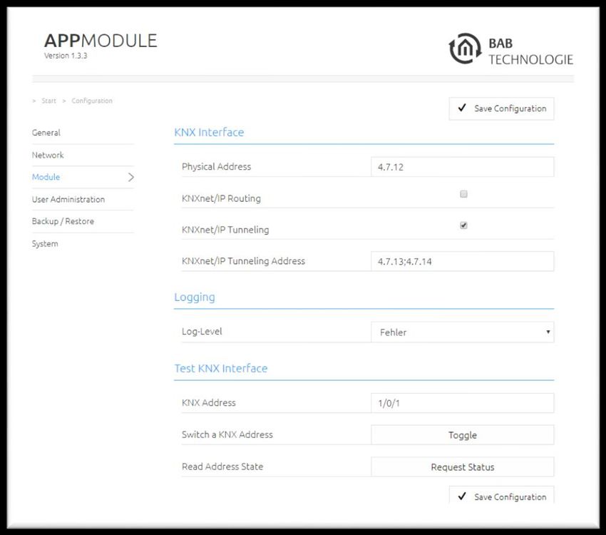
APPMODULE Documentation
2 ASSEMBLY
The operating voltage of the APP MODULE is 12-32 V DC
The device shown here is the APPMODULE KNX (form factor identical for all models), REG housing 4 TE.
Dimensions (width x height x depth): 70 x 90 x 63 mm
In order to ensure easy connection of the power supply, remove the screw plug-in terminals
(see figure below).
Now connect the power supply cables to the respective screw plug-in terminals (see figure
below). Please consider the polarity!
Now, you can replug the screw plug-in terminals into the APPMODULE.
In the next step, snap the device onto the mounting rail according to DIN EN 60715.
Figure 3: APPMODULE connection diagram
APPMODULE features
(1) KNX connection (type 10495) via screw plug-in terminal
(2) Power supply via screw plug-in terminal 12-32V DC
(3) USB connection (is not activated)
(4) RJ-45 female connector for Ethernet LAN
10 BAB TECHNOLOGIE GmbHAPPMODULE Documentation
2.1 LED STATUS
The APPMODULE has two DUO LEDs ("Power/Boot" and "Status"). Each DUO LED has a green and a red
LED.
POWER / BOOT LED
LED display Status
OFF The device is not ready for operation. No operating
voltage is supplied.
GREEN The device is ready for operation.
FLASHING ORANGE The device is booting.
STATUS LED
LED display Status
OFF The device is booting.
FLASHING GREEN The device has been started; the LED simulates a
"heartbeat". The flashing interval increases
depending on the device utilisation.
FLASHING RED Communication takes place via KNX.
Explanation:
The green "Power/Boot" LED lights up as soon as the APPMODULE is supplied with power. Two to three
seconds after the power supply has been switched on, this LED also starts to flash red (flashing orange)
until the booting process has been completed. Then the LED is permanently illuminated green, while
the "Status" LED flashes green (simulates a "heartbeat"). The flashing frequency increases depending on
the device utilisation.
It takes approx. 2 minutes to start the APPMODULE.
BAB TECHNOLOGIE GmbH 11APPMODULE Documentation
2.2 INITIAL OPERATION
If the APPMODULE has been mounted and started as described in chapter "Assembly", commissioning
can now be continued as specified below.
Factory setting on delivery:
IP address 192.168.1.224
Subnet mask 255.255.255.0
Username Admin
Password Admin
Device Name AppModule
Note: The password must be changed immediately when logging in for the first time. If the password is
lost, the device cannot be reset!
2.2.1 LANGUAGE
Web interface
The language used for the APPMODULE Web interface is based on the language set in the browser.
German and English are currently available in the APPMODULE. If the browser is set to a language other
than German or English, English is displayed in the APPMODULE interface.
Java application (EnOcean Editor)
The language in the “EnOcean Editor” Java-based application adjusts to the language set in the browser
after start-up from the browser. If the app is used in BAB STARTER, the language set in the operation
system applies. English is used if a language other than German or English is set.
2.2.2 SYSTEM REQUIREMENTS
Current browser (e.g. Firefox, Chrome, Safari, etc.)
Do not use Internet Explorer
If applicable, an app from the APPMARKET (https://www.bab-appmarket.de/de/)
For EnOcean configuration: BAB STARTER or current JVM & JVM browser plugin
2.2.3 ESTABLISHING CONNECTIONS
In order to configure the APPMODULE, a current browser and a network connection to the device are
required. If the device is in the condition of delivery, it can be accessed at the above-mentioned IP
address and the network settings must be adjusted to the address range, where necessary. Please follow
the information given in the chapter "Adjusting the network settings of your computer" for this
purpose.
12 BAB TECHNOLOGIE GmbHAPPMODULE Documentation
CALLING UP THE APPMODULE WEB INTERFACE
The APPMODULE is configured via its web interface so that it can be configured via each web browser.
The "EnOcean Editor" layers are Java applications and also require a Java Virtual Machine (JVM) or the
BAB STARTER (see "Establishing connections").
In order to call up the web interface, please proceed as described below:
Open a browser and enter the IP address of the APPMODULE into the address line (Information
about the factory settings can be found in chapter "Initial Operation")
Figure 4: APPMODULE start page
You will reach the APPMODULE start page. The “Login” unlocks the “Configuration” Functions
whereas “Information” shows general system information.
Use the user data to log in to the web interface: "Log In". (Information on the authorisation
settings can be found in chapter "Initial Operation")
Figure 5: Logging in to the web interface
BAB TECHNOLOGIE GmbH 13APPMODULE Documentation
You can then also access the "Configuration" menu item. See chapter "Configuration"
Figure 6: "Configuration" menu item
To return to the main menu, just click on the header graphic.
Figure 7: Back to the homepage
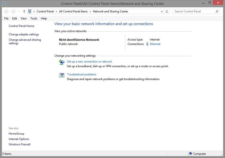
ADJUSTING THE NETWORK SETTINGS OF YOUR COMPUTER
In order to adjust the network settings of your computer and establish a connection to the device,
please proceed as described below:
Open the IP address settings (under Windows 7):
Click "Start Button" --> "Control Panel" --> "Network"
Select "Network Connection", then "LAN Connection" ("Intel PRO1000 GT" in the figure
below).
Figure 8: Windows Network and Sharing Center
14 BAB TECHNOLOGIE GmbHAPPMODULE Documentation
Then click "Properties":
Figure 9: "Ethernet" status
Select "Internet protocol Version 4 (TCP/IPv4)" and click "Properties" again:
Figure 10: Properties of the LAN connection
BAB TECHNOLOGIE GmbH 15APPMODULE Documentation
Now note down the current IP address settings or take a screenshot in order to ensure that you
can reset the IP address setting following the configuration of the APPMODULE.
Now change the IP address settings (IP address and subnet mask) as required:
Figure 11: TCP/IPv4 properties
Example of a valid configuration for the factory settings of the APPMODULE:
Free IP address: 192.168.1.228
Subnet mask: 255.255.255.0
Now confirm your input with "OK".
Close all windows until the "Windows Network and Sharing Center Settings" window is shown.
Thus, you have adjusted the network settings of your PC to those of the APPMODULE. You can access
the web interface of the APPMODULE by means of the browser. Restore the original network settings of
your PC by following the steps described above as soon as you have configured the APPMODULE
correspondingly.
If the IP address of your PC and your APPMODULE are in the same network mask, you can continue with
the configuration.
16 BAB TECHNOLOGIE GmbHAPPMODULE Documentation
ADJUSTING THE NETWORK SETTINGS OF THE APPMODULE
If the network prerequisites have been created, you can now access the configuration of the
APPMODULE in order to adjust the network settings to the local requirements there. To do this, please
proceed as described below:
Enter the IP address of the APPMODULE in the address line of your browser (for factory settings:
192.168.1.229).
Figure 12: APPMODULE Webinterface
The start page of the APPMODULE opens up. Click "Log In".
A login dialog appears. For factory settings, the login data is as follows:
Username: admin
Password: admin
Figure 13: Login dialog
Note: The password must be changed immediately when logging in for the first time. If the password is
lost, the device cannot be reset!
Note: Logging in only works if the browser is authorised to save cookies!
The view on the start page changes. You can now access the following levels:
App Manager
Configuration
Information
Log Out
BAB TECHNOLOGIE GmbH 17APPMODULE Documentation
In order to change the IP address of the APPMODULE, please click "Configuration"
Figure 14: APPMODULE – Main Menu
The configuration menu opens up. You can make the following settings in the "Network" menu item:
DHCP: If the DHCP service is enabled, the device will automatically obtain the network
settings. The DCHP service assigns the IP address, the network mask and the
default gateway to the APPMODULE. Therefore, a DHCP server, in private
networks mostly the router, must be available in the local network.
Note: If the DHCP service fails, the APPMODULE gets that with and is then
reachable under the default IP address, network mask and standard gateway.
Translated with www.DeepL.com/Translator
IP address / Field for the static assignment of IP addresses. Please make also sure that the
subnet mask / subnet mask (often 255.255.255.0) and the gateway entry are correct. (Often
gateway: the IP address of the WLAN router).
Note: Without a correct gateway entry, the device will not be able to
communicate with the Internet.
DNS server: DNS is the abbreviation for Domain Name System. The DNS server converts
Internet addresses, for example "www.bab-tec.de" into the IP address
"85.214.89.170" and vice versa. Without a valid DNS entry, NTP-, weather- or
UPnP services do not work.
NTP server: NTP is a free service for synchronising the system time of Internet-compatible
devices. If it is not possible to establish the connection to an NTP-Server, the
system time must always be checked and adjusted manually (see menu
"General")
NTP-Server list: e.g. http://www.pool.ntp.org/zone/europe
18 BAB TECHNOLOGIE GmbHAPPMODULE Documentation
Figure 15: APPMODULE Network configuration
Change the IP address settings as required. In order to save the settings made, click "Save
Configuration". The server in the device is restarted, the browser automatically connects to the new IP
address if possible.
Note: Please bear in mind that you might have to reset the IP address of your computer to the initial
value in order to be able to access the APPMODULE after the change has been made.
Specialty when activating DHCP
If you have activated DHCP for the APPMODULE according to the steps mentioned above, please use
the BAB STARTER like depicted in the chapter “Network” to find out the current IP-address.
BAB TECHNOLOGIE GmbH 19APPMODULE Documentation
3 APPMODULE IP
The IP APPMODULE (10491) is an IP for EIBPORT available thanks to the facility coupling protocol
implemented. A KNXnet/IP server is also implemented.
3.1 CONNECTING THE APPMODULE IP TO EIBPORT
Before the APPMODULE can communicate with EIBPORT, facility coupling needs to be set up.
Note: For facility coupling between EIBPORT and the APPMODULE to work, communication over UDP
with port 1735 (or another port if set) is required. Security installations in more complex networks can
prevent this communication.
SETTING UP THE CONNECTION IN THE APPMODULE
In the APPMODULE, go to the “Configuration” -> “Module” menu. Information on accessing the
APPMODULE Web interface can be found in “Calling up the APP MODULE web interface”.
Figure 16: APPMODULE IP Interface Extension
20 BAB TECHNOLOGIE GmbHAPPMODULE Documentation
Select “Extension” under “Select IP Interface”. This enables the “Extension interface” section.
Target host: For “Target host”, enter the address of the required EIBPORT (e.g.
192.168.1.222).
BMX UDP port: In the standard scenario, the facility coupling in EIBPORT is set to BMX port
1735 (you can check this in EIBPORT under “System” – “Configuration” – “Advanced EIB
(yabus) settings” – “BMX UDP port”).
Group address format: Not relevant here. Enter “3 Level (xx/y/zzz)”.
This sets up communication from the APPMODULE to EIBPORT. Communication from EIBPORT to the
APPMODULE must be set up at the EIBPORT end.
SETTING UP THE CONNECTION IN EIBPORT
To set up the connection in EIBPORT, you will need the EIBPORT “Facility coupling” job. For detailed
information on the job, please see the EIBPORT documentation.
In EIBPORT, open the “Job editor” (“Editor” – “Window” – “Job editor”) and add a new “Facility
coupling” job.
Figure 17: EIBPORT facility coupling job
BAB TECHNOLOGIE GmbH 21APPMODULE Documentation
The following fields must be configured:
Host name / IP address: Enter the address of the APPMODULE to which you wish to connect
here (e.g. 192.168.1.224).
Target system ID: Please do not change this value. The system ID must be “0”.
Rule #1: Enter the wildcard rule “*/*/*” in both fields (source & target). This rule transfers all
group addresses.
The job is active as soon as you save and the group addresses are transferred.
22 BAB TECHNOLOGIE GmbHAPPMODULE Documentation
3.2 USING KNX NET/IP IN THE APPMODULE IP
The IP APPMODULE contains a complete KNXnet/IP server. KNXnet/IP Routing can be used for a
connection to KNX (must be provided by another device with a KNX interface, e. g. a KNX-IP-Router) and
KNXnet/IP Tunneling as an interface for ETS.
Proceed as follows to set up the KNXnet/IP server:
Open the “Configuration” – “Module” and select “KNXnet/IP” under “Select interface”. This
enables the “KNX interface”.
Figure 18: APPMODULE IP Interface KNXnet/IP
More information on KNXnet/IP setup can be found in “KNX configuration”.
.
BAB TECHNOLOGIE GmbH 23APPMODULE Documentation
4 APPMODULE KNX
4.1 APPMODULE KNX COMMISSIONING
There is no ETS application for the APPMODULE KNX (item no. 10495). All KNX-related settings are
made over the Web interface of the APPMODULE.
Note: For the ETS project, please use a dummy application to record the use of the physical address of
the APPMODULE.
Access the website of the APPMODULE and log on (see “Calling up the APP MODULE web
interface”).
Switch to the “Configuration” > “KNX” menu.
Figure 19: KNX configuration
24 BAB TECHNOLOGIE GmbHAPPMODULE Documentation
Change the “Physical address”. Please follow the rules for assigning physical addresses in a KNX
system.
Figure 20: KNX – Physical Address
Assign at least 2 physical addresses (not used in the relevant line) for KNXnet/IP Tunneling.
Figure 21: KNX – assigning a KNXnet/IP tunneling address
Note: These addresses are required for establishing a connection for the commissioning software ETS for
use of the APPMODULE as an interface to KNX. As of ETS 5, at least 2 free addresses are required here.
Save the configuration.
Figure 22: Saving the configuration
BAB TECHNOLOGIE GmbH 25APPMODULE Documentation
4.1.1 KNX CONFIGURATION
The KNX-specific settings of the APPMODULE are made in the “KNX” menu. The KNX settings are
available both for a APPMODULE KNX (10495) and for the APPMODULE EnOcean (13501) &
APPMODULE IP (10491). For the APPMODULE EnOcean & APPMODULE IP, the settings are used to
configure the KNXnet/IP server.
Physical address: Here, you can determine the physical address to be used by the
APPMODULE in the KNX network. Please make sure that the
physical address corresponds to the installation site and does
not occur twice.
KNXnet/IP Routing: Activates KNXnet/IP Routing for coupling lines and areas via IP.
Can only be activated if the physical address corresponds to
that of a line or area coupler. KNXnet/IP Routing is based on
multicast and all devices send to a multicast group
224.0.23.12. Since multicast packages are usually not
transferred by routers, “routing” only works within a subnet.
KNXnet/IP Tunneling: Activates KNXnet/IP Tunneling access to the device. This
connection can be used to program KNX devices or to
exchange data. The APPMODULE is the server. The above
address is used as the physical address for the connection. For
each address, only one connection can be established at any
one time. On the TCP/IP layer, the connection is made by
means of unicast to UDP port 3671.
KNXnet/IP Tunneling Addresses: After activating the KNXnet / IP tunneling, the input field for
the tunneling addresses is displayed. This address is used by the
internal KNXnet / IP server for a KNXnet / IP tunneling
connection established to the device (use of the APPMODULE
as programming interface). Please note that this address must
not be the same as the physical address (see above) and that it
is not used by any other device in the line.
Note: These addresses are used to establish a connection with
the ETS commissioning software to use the APPMODULE as an
interface to KNX. Since ETS 5, at least 2 free addresses are
required here.
Click “Save configuration” to apply the settings.
Note: The KNXnet/IP app for EnOcean is available in the APP MARKET for the APPMODULE EnOcean
(13501).
26 BAB TECHNOLOGIE GmbHAPPMODULE Documentation
4.1.2 ETS INSIDE SERVER
In order to use the functions of ETS Inside for your mobile service, you have to activate the server in the
menu "ETS Inside Server" (see figure below).
Figure 23: ETS Inside Server
According to your existing ETS Inside licenses, the KNX USB dongle must be connected to the USB port
on APPMODULE. This dongle is not part of the delivery for APPMODULE and can be purchased
separately via KNX.org (www.knx.org).
By registering the dongle at KNX Association you will receive a license file. You still need to transfer this
license to the APPMODULE. To do this, select the file via "Select license file" and upload the license.
For any questions of registration, please use the support of the KNX Association:
https://support.knx.org/hc/en-us/articles/214496505-Licensing-ETS-Inside
Now the ETS Inside Server is ready for use. Further you have access to the KNX network via the ETS Inside
Server with the ETS Inside Client, installed the APP on your mobile device. On one hand the ETS Inside
Client and Server, as well as the APPMODULE and the required KNX line are connected via the
respective network. The handling of ETS Inside is not part of this manual. Please use the detailed
information provided by the KNX Association (www.knx.org).
As an alternative to the access with licence of the ETS Inside, you can use the ETS Inside for testing,
without USB dongle and license file in DEMO mode, with the same restrictions.
Note: By using the KNX IP router functionality integrated in the APPMODULE you have the option of
flexibly using the integrated KNX Inside Server for the required KNX network. To do this, you only have to
make the appropriate settings so that the APPMODULE acts as a KNX IP router, linked in via KNX IP.
BAB TECHNOLOGIE GmbH 27APPMODULE Documentation
5 APPMODULE ENOCEAN
5.1 INITIAL OPERATION OF APPMODULE ENOCEAN
Please connect the plug of the magnetic base antenna to the SMA connector at the housing. Without
an antenna, the device has only low transmission and received powers. As soon as the device has
started, the EnOcean interface can be used.
Further information on the teaching and controlling of EnOcean devices can be found in chapter
"Usage of the EnOcean Editor"
TECHNICAL DETAILS ABOUT THE ENOCEAN INTERFACE
EnOcean (868 Mhz):
Operating frequency: 868.3 Mhz
Range: 300 m in the free field / 30 m in the building
(depending on the building material)
Input objects: Any number
Output objects: 128
External antenna: 2.50 m cable, magnetic base and SMA plug connector.
ENOCEN KOMPATIBILITÄT
Eltako
Profil Beschreibung Produkte
80-02-01 Eltako Dimmen Eltako FUD14 / FUD61 / FDDT65B
80-03-01 Eltako Beschattung Eltako FSB14 / FSB61
80-04-01 Eltako Bewegungsmelder + Sensor Eltako FBH65S
80-07-01 Eltako Tipp-Funk-Taster-Tracker Eltako TF-TTB
Vier Byte
Profil Beschreibung
a5-10-05 Temperatur, Sollwert, Anwesenheit
a5-08-01 Bewegungsmelder mit Licht, Temperatur Sensor
Ein Byte
Profil Beschreibung
d5-00-01 Eingangskontakt
RPS
Profil Beschreibung
f6-02-01 Rocker Switch
f6-03-01 Taster mit vier Wippen
f6-10-00 Fenstergriff
28 BAB TECHNOLOGIE GmbHAPPMODULE Documentation
5.2 CALLING UP THE ENOCEAN EDITOR
A detailed description for the EnOcean Editor can be found in chapter "Usage of the EnOcean Editor"!
Figure 24: Configuration – EnOcean Editor
1. You call the EnOcean Editor directly in the browser.
5.3 USAGE OF THE ENOCEAN EDITOR
In order to open the EnOcean Editor please follow the description in chapter “Calling up the EnOcean
Editor”!
5.3.1 OPERATING PRINCIPLE ENOCEAN
An EnOcean radio network consists of sensors and actuators. The sensors utilize your ambient energy to
transmit the corresponding radio signal. So that an actuator can interpret and respond to the signals of
a sensor, the actuator must be adapted to the sensor. The so-called EnOcean Profiles (EEP) determine
how the data provided by the sensor are to be interpreted. Thus, it is important that sensor and
actuator utilize the same EnOcean Profile (EEP).
Device categories / sensors
EnOcean distinguishes between three device categories in its sensor technology. The device category
gives information about the kind of EnOcean signal involved and simultaneously about what the
receiver can expect.
Switch module: A module which sends out a corresponding radio signal via user interaction.
That is switches, rockers, position and key card switches as well as window handles.
1 byte sensor: A sensor which sends out information of 1 byte size.
4 byte sensor: A sensor which sends out information of 4 byte size.
Actuators
Actuators will perform their controlling on the basis of sensor signals. Therefore, sensor and actuator
have to be adapted to each other. Thus, it is important to know which EnOcean profile is to be
emulated to address a LINKMOUDULE actuator correctly. The actuator manufacturer will inform you
about which profile the actuator utilizes.
BAB TECHNOLOGIE GmbH 29APPMODULE Documentation
EnOcean Profiles (EEP)
The EnOcean profiles (EnOcean Equipment Profile - EEP) define the device category, the function and
the device specification. During the APPMODULE configuration, the KNX parameters automatically
adapt to the selected profile. The profile consists of 3 number pairs separated by a hyphen: XX-XX-XX
The different positions represent the following:
ORG-FUNC-TYPE
ORG determines which messages form the communication base (see also 'Device
categories/sensors').
FUNC determines which device is involved, that is e.g. a switch or a temperature sensor.
TYPE determines the exact specifications of the device functionality.
Transmitter ID (Trans. ID)
Is a definite device address which only exists once. This address allows the sending device to be
identified.
Teaching Telegram / LRN Telegram
Is a special telegram used to "teach" the sensor to recognize the actuator, that is, to adapt the actuator
to the sensor. It is important for the actuator to know from which hardware address it gets its sensor
data. There are several kinds of adapting mechanisms. Please consider the respective descriptions.
5.3.2 ENOCEAN CONFIGURATION
The APPMODULE internally works with the KNX group address system. In order to continue to use
received EnOcean signals within the device or to trigger EnOcean telegrams, KNX group addresses must
be used. You will find information about this in chapter "KNX Addressing".
In order to access the corresponding APPMODULE configuration mask, please consider the
chapter"Calling up the EnOcean Editor"). The window generally consists of three areas:
Figure 25: EnOcean Configuration - Devices
30 BAB TECHNOLOGIE GmbHAPPMODULE Documentation
Figure 26: EnOcean Configuration - Monitor
Settings:
Settings: You can configure the EnOcean module here.
EnOcean Devices: Lists all EnOcean devices sorted by device id (trans. id).
EnOcean Monitor: Lists all received EnOcean telegrams sorted by the time at which they were
received.
BAB TECHNOLOGIE GmbH 31APPMODULE Documentation
5.3.3 ENOCEAN SETTINGS
Figure 27: EnOcean Settings
The EnOcean settings show the hardware parameters of the incorporated EnOcean module (TCM 300
Transceiver). The following settings can be performed:
EnOcean active
Here, you can switch the module on or off.
Repeater
The repeater function is used to repeat a receiving signal in order to increase its range. The following
settings are available:
Check box activates: Repeater function is turned on.
Level 1: The telegram is repeated by one repeater only.
Level 2: The telegram is repeated by two repeaters.
RX sensitivity
Determine the receiving sensitivity in which you want the EnOcean module to work. You can choose
between "Low" and "High".
32 BAB TECHNOLOGIE GmbHAPPMODULE Documentation
5.3.4 ENOCEAN DEVICE TEACH-IN PROCEDURE
All EnOcean devices within range are displayed both in the device list and in the telegram list as they
are sending something. As already mentioned, the EnOcean telegram must be connected with a group
address in order to make it usable for the APPMODULE. This is done as follows:
1. Mark the device of interest in the device list.
Figure 28: Calling up properties
All Devices: Show all devices
Configured Devices: Show only the devices which have already been configured
New / Unnamed Devices: Show only the new and unnamed devices
Advice: If you are not sure which device has which Trans. ID, activate the device of interest and look up
in the device list for which device the telegram counter increases (column "telegrams").
2. When you have detected the device of interest, mark it with the mouse, press the right mouse
button and click 'Properties'. Alternatively, double-click on the device.
3. The window "EnOcean Device Configuration" will open. Via this dialogue, the EnOcean devices
will be "adapted.
Figure 29: EnOcean Device Configuration
BAB TECHNOLOGIE GmbH 33APPMODULE Documentation
4. Initially, assign a definite "Device Name", referring to the device function. In the input screen,
you will further find the following parameters:
ID: This is the unique device address through which the device is identified.
EnOcean Equipment Profile (EEP): The different EnOcean devices are defined via so-called
profiles. Hereby, the device category involved is detected as early as at the signal input and a
pre-selection is made. Then it is also possible to select from the profiles known from the
APPMODULE. As soon as a profile is selected, the corresponding KNX parameters are shown
underneath.
5. Select the corresponding profile of your EnOcean device. If you are not sure about which profile
your device 'speaks', please contact the manufacturer of the device:
Different parameters appear depending on which profile has been selected. If one switch (rocker) has
been selected, various additional functions can be carried out (see chapter "Configuration example for
EnOcean ").
6. Choose your switch type in "Parameters".
Figure 30: Parameters
Single rocker Double rocker
If you choose switch type "Double rocker with dual press action", the APPMODULE will give your two
rockers switch a third switch function. This function will be triggered when you press both rockers
simultaneously.
34 BAB TECHNOLOGIE GmbHAPPMODULE Documentation
7. Next, open the "Address Configuration" configuration panel
8. Now, enter the corresponding KNX group addresses in the address fields to obtain a connection
to the selected EnOcean device. You will find detailed information about the KNX group
addresses and their assignment in chapter "KNX Addressing".
9. When you have entered the addresses in the parameters as requested, close the EnOcean
Device Configuration window.
10. Save the changes in the window "EnOcean Configuration" via the button “Save & Close“ or
"Assume" (the window stays open).
As soon as this step is taken, the entered KNX telegrams are triggered via EnOcean signals. In order to
be able to use the addresses more easily later, you should enter them into the ESF data with a definite
designation (see Chapter "KNX Addressing")
BAB TECHNOLOGIE GmbH 35APPMODULE Documentation
5.3.5 EMULATING ENOCEAN DEVICES
The APPMODULE provides a Transceiver Module which not only permits receiving but also sending
EnOcean telegrams. In order to do this, the APPMODULE emulates an EnOcean device. Via a
configuration mask, you can determine which device is emulated with which KNX telegram by the
APPMODULE (the device internally works with KNX group addresses also during the EnOcean execution).
Creating an emulated device
Click on the button “Add feedback device”
to create a new emulated EnOcean
device. A new window will be opened.
Add feedback device
Depending on which actuator is supposed
to be controlled, the matching device
profile needs to be determined. The new
emulated device will be added to the list
of “EnOcean devices”
36 BAB TECHNOLOGIE GmbHAPPMODULE Documentation
Defining emulated device
The device assigned in this way is initially provided with a definite device name. Additionally, the
following parameters are presented
ID: Is the definite hardware address you have selected before. Can not be modified at this point.
EnOcean Equipment Profil (EEP): Here, the profile the emulated device should use is selected.
For more information regarding parameter and address configuration, please see
„Configuration example for EnOcean “.
Simulate push the button
Here you can simulate a push button for each rocker, which sends a telegram.
BAB TECHNOLOGIE GmbH 37APPMODULE Documentation
5.3.6 KNX ADDRESSING
The APPMODULE addressing concept is based on the group addressing of the KNX system. Sending
EnOcean Telegrams as well as transmitting received telegrams is performed based on KNX group
addresses only. The KNX group address is a 16-bit address which is split in a so-called 'real' and a 'virtual'
section. Additionally, there is a 2-digit as well as a 3-digit representation:
3-digit:
MG= Main Group / CG= Central Group / SG= Subgroup
MG / CG / SG
2-digit:
MG= Main Group / SG= Subgroup
MG / SG
Note: The APPMODULE interface only supports the 3-digit representation.
Real / Virtual Address Space
The KNX address space ranges in total from 0/0/0 to 31/7/255 (in the 3-digit representation). Therein,
the range from 15/7/255 is designated as real address space and the address space from 16/0/0 to
31/7/255 as virtual address space.
Note: For the communication between EnOcean and KNXnet/IP Routing, only the real address space is
used.
38 BAB TECHNOLOGIE GmbHAPPMODULE Documentation
5.3.7 CONFIGURATION EXAMPLE FOR ENOCEAN PUSH-
BUTTON (ROCKER)
In the following, an exemplary configuration for sending and receiving of an EnOcean push-button
(Rocker) profile (profile "05-02-01: 2Rockers, Light & Blind") is shown.
APPMODULE AS THE RECEIVER (ACTUATOR)
This switch provides either one or two rockers and transmits their status within a radio signal. In order to
link these radio signals with KNX, various functions are available:
Configuring Parameters:
Invert: Inverts the
telegram content sent
on the KNX addresses.
Telegram value “1”
becomes “0” and vice
versa.
Individual Timings:
Individual timings
determine the length of
button presses for
switch, move, step.
Separate Action: You
can assign further KNX
addresses for the
separate action “both
rockers at the same
time”. Please note that
this is only possible for
buttons with two
rockers.
Assigning Addresses:
Switching / Dimming:
The EnOcean button can
be used as switch and
dimmer. A long-press
will be interpreted as a
dimming command.
When used as a switch,
the button will send a 0
on “Off” and a 1 on
“On”.
Push Button: Pressing
“Off” will send an EIS 1
telegram with value 0.
Upon releasing the
button, another
telegram with value 1
Figure 31: Receiving KNX parameters
will be sent. Pressing “On” will
send an EIS 1 telegram with value 1. Upon releasing the button, another telegram with value 0
will be be sent. You can assign one address for either position (I and O).
Blind: Assign one address each for the commands “Move” and “Step” (EIS 1).
BAB TECHNOLOGIE GmbH 39You can also read