Load Balancing Microsoft Exchange 2019 - Loadbalancer.org
←
→
Page content transcription
If your browser does not render page correctly, please read the page content below

Load Balancing Microsoft Exchange
2019
Version 1.1.0

Table of Contents
1. About this Guide . . . . . . . . . . . . . . . . . . . . . . . . . . . . . . . . . . . . . . . . . . . . . . . . . . . . . . . . . . . . . . . . . . . . . . . . . . . . . . . . . . . . . 4
2. Loadbalancer.org Appliances Supported . . . . . . . . . . . . . . . . . . . . . . . . . . . . . . . . . . . . . . . . . . . . . . . . . . . . . . . . . . . . . . . 4
3. Loadbalancer.org Software Versions Supported . . . . . . . . . . . . . . . . . . . . . . . . . . . . . . . . . . . . . . . . . . . . . . . . . . . . . . . . . 4
4. Microsoft Exchange Software Versions Supported . . . . . . . . . . . . . . . . . . . . . . . . . . . . . . . . . . . . . . . . . . . . . . . . . . . . . . . 4
5. Exchange Server 2019 . . . . . . . . . . . . . . . . . . . . . . . . . . . . . . . . . . . . . . . . . . . . . . . . . . . . . . . . . . . . . . . . . . . . . . . . . . . . . . . 4
6. Exchange 2019 Server Roles. . . . . . . . . . . . . . . . . . . . . . . . . . . . . . . . . . . . . . . . . . . . . . . . . . . . . . . . . . . . . . . . . . . . . . . . . . 4
7. Load Balancing Exchange 2019 . . . . . . . . . . . . . . . . . . . . . . . . . . . . . . . . . . . . . . . . . . . . . . . . . . . . . . . . . . . . . . . . . . . . . . . 5
    Load Balancing & HA Requirements. . . . . . . . . . . . . . . . . . . . . . . . . . . . . . . . . . . . . . . . . . . . . . . . . . . . . . . . . . . . . . . . . . . 5
        Database Availability Group (DAG) . . . . . . . . . . . . . . . . . . . . . . . . . . . . . . . . . . . . . . . . . . . . . . . . . . . . . . . . . . . . . . . . . 5
    Persistence (aka Server Affinity) . . . . . . . . . . . . . . . . . . . . . . . . . . . . . . . . . . . . . . . . . . . . . . . . . . . . . . . . . . . . . . . . . . . . . . 5
    Port Requirements . . . . . . . . . . . . . . . . . . . . . . . . . . . . . . . . . . . . . . . . . . . . . . . . . . . . . . . . . . . . . . . . . . . . . . . . . . . . . . . . . . 5
    SSL Termination . . . . . . . . . . . . . . . . . . . . . . . . . . . . . . . . . . . . . . . . . . . . . . . . . . . . . . . . . . . . . . . . . . . . . . . . . . . . . . . . . . . . 6
    HTTPS Namespaces & IP addresses . . . . . . . . . . . . . . . . . . . . . . . . . . . . . . . . . . . . . . . . . . . . . . . . . . . . . . . . . . . . . . . . . . 6
    Health-Checks. . . . . . . . . . . . . . . . . . . . . . . . . . . . . . . . . . . . . . . . . . . . . . . . . . . . . . . . . . . . . . . . . . . . . . . . . . . . . . . . . . . . . . 7
    Load Balancer Deployment Concept . . . . . . . . . . . . . . . . . . . . . . . . . . . . . . . . . . . . . . . . . . . . . . . . . . . . . . . . . . . . . . . . . . 7
    Virtual Service (VIP) Requirements . . . . . . . . . . . . . . . . . . . . . . . . . . . . . . . . . . . . . . . . . . . . . . . . . . . . . . . . . . . . . . . . . . . . 8
    Load Balancer Deployment Modes. . . . . . . . . . . . . . . . . . . . . . . . . . . . . . . . . . . . . . . . . . . . . . . . . . . . . . . . . . . . . . . . . . . . 8
    Layer 7 SNAT Mode . . . . . . . . . . . . . . . . . . . . . . . . . . . . . . . . . . . . . . . . . . . . . . . . . . . . . . . . . . . . . . . . . . . . . . . . . . . . . . . . . 8
    Layer 4 DR Mode . . . . . . . . . . . . . . . . . . . . . . . . . . . . . . . . . . . . . . . . . . . . . . . . . . . . . . . . . . . . . . . . . . . . . . . . . . . . . . . . . . . 9
    Our Recommendation . . . . . . . . . . . . . . . . . . . . . . . . . . . . . . . . . . . . . . . . . . . . . . . . . . . . . . . . . . . . . . . . . . . . . . . . . . . . . . 10
        Is SSL Offloading Required? . . . . . . . . . . . . . . . . . . . . . . . . . . . . . . . . . . . . . . . . . . . . . . . . . . . . . . . . . . . . . . . . . . . . . . 10
8. Configuring Exchange 2019 for Load Balancing . . . . . . . . . . . . . . . . . . . . . . . . . . . . . . . . . . . . . . . . . . . . . . . . . . . . . . . . . 11
    1) External Access Domain . . . . . . . . . . . . . . . . . . . . . . . . . . . . . . . . . . . . . . . . . . . . . . . . . . . . . . . . . . . . . . . . . . . . . . . . . . . 11
    2) Virtual Directories. . . . . . . . . . . . . . . . . . . . . . . . . . . . . . . . . . . . . . . . . . . . . . . . . . . . . . . . . . . . . . . . . . . . . . . . . . . . . . . . 12
    3) Outlook Anywhere . . . . . . . . . . . . . . . . . . . . . . . . . . . . . . . . . . . . . . . . . . . . . . . . . . . . . . . . . . . . . . . . . . . . . . . . . . . . . . . 12
    4) Autodiscover . . . . . . . . . . . . . . . . . . . . . . . . . . . . . . . . . . . . . . . . . . . . . . . . . . . . . . . . . . . . . . . . . . . . . . . . . . . . . . . . . . . . 13
    5) Certificates. . . . . . . . . . . . . . . . . . . . . . . . . . . . . . . . . . . . . . . . . . . . . . . . . . . . . . . . . . . . . . . . . . . . . . . . . . . . . . . . . . . . . . 15
    6) Send & Receive Connectors. . . . . . . . . . . . . . . . . . . . . . . . . . . . . . . . . . . . . . . . . . . . . . . . . . . . . . . . . . . . . . . . . . . . . . . 15
        Adding Connectors. . . . . . . . . . . . . . . . . . . . . . . . . . . . . . . . . . . . . . . . . . . . . . . . . . . . . . . . . . . . . . . . . . . . . . . . . . . . . . 16
    7) DNS Configuration . . . . . . . . . . . . . . . . . . . . . . . . . . . . . . . . . . . . . . . . . . . . . . . . . . . . . . . . . . . . . . . . . . . . . . . . . . . . . . . 16
    8) Additional Exchange Server Configuration Steps (depends on Load balancing method) . . . . . . . . . . . . . . . . . . 16
        Layer 7 SNAT Mode . . . . . . . . . . . . . . . . . . . . . . . . . . . . . . . . . . . . . . . . . . . . . . . . . . . . . . . . . . . . . . . . . . . . . . . . . . . . . 16
        Layer 4 DR Mode. . . . . . . . . . . . . . . . . . . . . . . . . . . . . . . . . . . . . . . . . . . . . . . . . . . . . . . . . . . . . . . . . . . . . . . . . . . . . . . . 16
    9) IIS Restart (Important). . . . . . . . . . . . . . . . . . . . . . . . . . . . . . . . . . . . . . . . . . . . . . . . . . . . . . . . . . . . . . . . . . . . . . . . . . . . . 17
9. Loadbalancer.org Appliance – the Basics . . . . . . . . . . . . . . . . . . . . . . . . . . . . . . . . . . . . . . . . . . . . . . . . . . . . . . . . . . . . . . 17
    Virtual Appliance . . . . . . . . . . . . . . . . . . . . . . . . . . . . . . . . . . . . . . . . . . . . . . . . . . . . . . . . . . . . . . . . . . . . . . . . . . . . . . . . . . . 17
    Initial Network Configuration. . . . . . . . . . . . . . . . . . . . . . . . . . . . . . . . . . . . . . . . . . . . . . . . . . . . . . . . . . . . . . . . . . . . . . . . . 17
    Accessing the WebUI . . . . . . . . . . . . . . . . . . . . . . . . . . . . . . . . . . . . . . . . . . . . . . . . . . . . . . . . . . . . . . . . . . . . . . . . . . . . . . . 17
        Main Menu Options. . . . . . . . . . . . . . . . . . . . . . . . . . . . . . . . . . . . . . . . . . . . . . . . . . . . . . . . . . . . . . . . . . . . . . . . . . . . . . 19
    HA Clustered Pair Configuration . . . . . . . . . . . . . . . . . . . . . . . . . . . . . . . . . . . . . . . . . . . . . . . . . . . . . . . . . . . . . . . . . . . . . 19
10. Appliance Configuration – Using Layer 7 SNAT Mode (without SSL Offload) . . . . . . . . . . . . . . . . . . . . . . . . . . . . . . . 19
    Load Balancer Deployment Overview . . . . . . . . . . . . . . . . . . . . . . . . . . . . . . . . . . . . . . . . . . . . . . . . . . . . . . . . . . . . . . . . 19
    Load Balancer Configuration . . . . . . . . . . . . . . . . . . . . . . . . . . . . . . . . . . . . . . . . . . . . . . . . . . . . . . . . . . . . . . . . . . . . . . . . 20
        Configure VIP1 – Mailbox Server Role HTTPS Services . . . . . . . . . . . . . . . . . . . . . . . . . . . . . . . . . . . . . . . . . . . . . . 20
        Configure VIP2 – Mailbox Server Role IMAP4/POP3 Services . . . . . . . . . . . . . . . . . . . . . . . . . . . . . . . . . . . . . . . . 22
        Configure VIP3 – Mailbox Server Role SMTP Services . . . . . . . . . . . . . . . . . . . . . . . . . . . . . . . . . . . . . . . . . . . . . . . 23
        Configuring Firewall Rules to Lockdown SMTP . . . . . . . . . . . . . . . . . . . . . . . . . . . . . . . . . . . . . . . . . . . . . . . . . . . . . 24
        Additional Settings if using Kerberos Authentication . . . . . . . . . . . . . . . . . . . . . . . . . . . . . . . . . . . . . . . . . . . . . . . . 24
        Finalizing the Configuration . . . . . . . . . . . . . . . . . . . . . . . . . . . . . . . . . . . . . . . . . . . . . . . . . . . . . . . . . . . . . . . . . . . . . . 25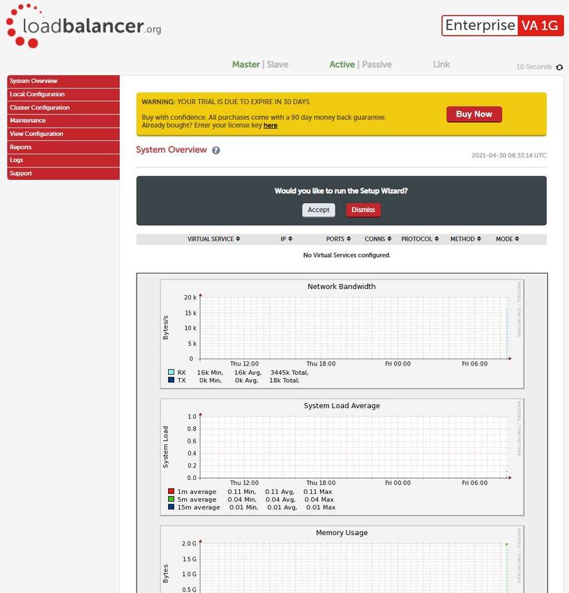
Exchange Server Configuration Steps . . . . . . . . . . . . . . . . . . . . . . . . . . . . . . . . . . . . . . . . . . . . . . . . . . . . . . . . . . . . . . . . 25
11. Appliance Configuration – Using Layer 7 SNAT Mode (with SSL Offload) . . . . . . . . . . . . . . . . . . . . . . . . . . . . . . . . . . 25
    Load Balancer Deployment Overview . . . . . . . . . . . . . . . . . . . . . . . . . . . . . . . . . . . . . . . . . . . . . . . . . . . . . . . . . . . . . . . . 25
    Load Balancer Configuration . . . . . . . . . . . . . . . . . . . . . . . . . . . . . . . . . . . . . . . . . . . . . . . . . . . . . . . . . . . . . . . . . . . . . . . . 26
       Configure VIP1 – Mailbox Server Role HTTPS Services . . . . . . . . . . . . . . . . . . . . . . . . . . . . . . . . . . . . . . . . . . . . . . 26
       Configure VIP2 – Mailbox Server Role IMAP4/POP3 Services . . . . . . . . . . . . . . . . . . . . . . . . . . . . . . . . . . . . . . . . 29
       Configure VIP3 – Mailbox Server Role SMTP Services . . . . . . . . . . . . . . . . . . . . . . . . . . . . . . . . . . . . . . . . . . . . . . . 30
       Configuring Firewall Rules to Lockdown SMTP . . . . . . . . . . . . . . . . . . . . . . . . . . . . . . . . . . . . . . . . . . . . . . . . . . . . . . 31
       Additional Settings if using Kerberos Authentication . . . . . . . . . . . . . . . . . . . . . . . . . . . . . . . . . . . . . . . . . . . . . . . . . 31
       Finalizing the Configuration . . . . . . . . . . . . . . . . . . . . . . . . . . . . . . . . . . . . . . . . . . . . . . . . . . . . . . . . . . . . . . . . . . . . . . 32
    Exchange Server Configuration Steps . . . . . . . . . . . . . . . . . . . . . . . . . . . . . . . . . . . . . . . . . . . . . . . . . . . . . . . . . . . . . . . . 32
       Configure IIS logging to Capture XFF Header IP Addresses . . . . . . . . . . . . . . . . . . . . . . . . . . . . . . . . . . . . . . . . . . 32
12. Appliance Configuration – Using Layer 4 DR Mode . . . . . . . . . . . . . . . . . . . . . . . . . . . . . . . . . . . . . . . . . . . . . . . . . . . . 32
    Load Balancer Deployment Overview . . . . . . . . . . . . . . . . . . . . . . . . . . . . . . . . . . . . . . . . . . . . . . . . . . . . . . . . . . . . . . . . 32
    Load Balancer Configuration . . . . . . . . . . . . . . . . . . . . . . . . . . . . . . . . . . . . . . . . . . . . . . . . . . . . . . . . . . . . . . . . . . . . . . . . 33
       Configure VIP1 – Mailbox Server Role HTTPS Services . . . . . . . . . . . . . . . . . . . . . . . . . . . . . . . . . . . . . . . . . . . . . . 33
       Configure VIP2 – Mailbox Server Role IMAP4/POP3 Services . . . . . . . . . . . . . . . . . . . . . . . . . . . . . . . . . . . . . . . . 34
       Configure VIP3 – Mailbox Server Role SMTP Services . . . . . . . . . . . . . . . . . . . . . . . . . . . . . . . . . . . . . . . . . . . . . . . 36
    Exchange Server Configuration Steps . . . . . . . . . . . . . . . . . . . . . . . . . . . . . . . . . . . . . . . . . . . . . . . . . . . . . . . . . . . . . . . . 37
13. Testing & Verification. . . . . . . . . . . . . . . . . . . . . . . . . . . . . . . . . . . . . . . . . . . . . . . . . . . . . . . . . . . . . . . . . . . . . . . . . . . . . . . 37
    Useful Exchange 2019 & Other Microsoft Tools . . . . . . . . . . . . . . . . . . . . . . . . . . . . . . . . . . . . . . . . . . . . . . . . . . . . . . . . 37
       Testing Server Health-checks using Set-ServerComponentState . . . . . . . . . . . . . . . . . . . . . . . . . . . . . . . . . . . . . . 37
       Testing Mailflow . . . . . . . . . . . . . . . . . . . . . . . . . . . . . . . . . . . . . . . . . . . . . . . . . . . . . . . . . . . . . . . . . . . . . . . . . . . . . . . . 38
       Testing SMTP Mail flow using Telnet . . . . . . . . . . . . . . . . . . . . . . . . . . . . . . . . . . . . . . . . . . . . . . . . . . . . . . . . . . . . . . 39
       Microsoft Exchange Testing Tool . . . . . . . . . . . . . . . . . . . . . . . . . . . . . . . . . . . . . . . . . . . . . . . . . . . . . . . . . . . . . . . . . 40
    Useful Appliance based Tools & Features . . . . . . . . . . . . . . . . . . . . . . . . . . . . . . . . . . . . . . . . . . . . . . . . . . . . . . . . . . . . 40
       Using System Overview . . . . . . . . . . . . . . . . . . . . . . . . . . . . . . . . . . . . . . . . . . . . . . . . . . . . . . . . . . . . . . . . . . . . . . . . . 40
       Layer 4 Status Report . . . . . . . . . . . . . . . . . . . . . . . . . . . . . . . . . . . . . . . . . . . . . . . . . . . . . . . . . . . . . . . . . . . . . . . . . . . . 41
       Layer 7 Statistics Report. . . . . . . . . . . . . . . . . . . . . . . . . . . . . . . . . . . . . . . . . . . . . . . . . . . . . . . . . . . . . . . . . . . . . . . . . . 41
       Appliance Logs . . . . . . . . . . . . . . . . . . . . . . . . . . . . . . . . . . . . . . . . . . . . . . . . . . . . . . . . . . . . . . . . . . . . . . . . . . . . . . . . . 41
14. Technical Support . . . . . . . . . . . . . . . . . . . . . . . . . . . . . . . . . . . . . . . . . . . . . . . . . . . . . . . . . . . . . . . . . . . . . . . . . . . . . . . . . . 41
15. Further Documentation. . . . . . . . . . . . . . . . . . . . . . . . . . . . . . . . . . . . . . . . . . . . . . . . . . . . . . . . . . . . . . . . . . . . . . . . . . . . . 42
16. Conclusion . . . . . . . . . . . . . . . . . . . . . . . . . . . . . . . . . . . . . . . . . . . . . . . . . . . . . . . . . . . . . . . . . . . . . . . . . . . . . . . . . . . . . . . 42
17. Appendix . . . . . . . . . . . . . . . . . . . . . . . . . . . . . . . . . . . . . . . . . . . . . . . . . . . . . . . . . . . . . . . . . . . . . . . . . . . . . . . . . . . . . . . . . 43
    Configuring Firewall Rules to Lockdown SMTP . . . . . . . . . . . . . . . . . . . . . . . . . . . . . . . . . . . . . . . . . . . . . . . . . . . . . . . . 43
    Enabling Layer 7 Transparency using TProxy . . . . . . . . . . . . . . . . . . . . . . . . . . . . . . . . . . . . . . . . . . . . . . . . . . . . . . . . . . 44
    Using a Layer 4 Virtual Service for SMTP . . . . . . . . . . . . . . . . . . . . . . . . . . . . . . . . . . . . . . . . . . . . . . . . . . . . . . . . . . . . . 44
       Layer 4 DR Mode - Solving the ARP Problem . . . . . . . . . . . . . . . . . . . . . . . . . . . . . . . . . . . . . . . . . . . . . . . . . . . . . . . 45
    Configuring an HTTP to HTTPS redirect for OWA . . . . . . . . . . . . . . . . . . . . . . . . . . . . . . . . . . . . . . . . . . . . . . . . . . . . . . 45
    Configuring HA - Adding a Slave Appliance . . . . . . . . . . . . . . . . . . . . . . . . . . . . . . . . . . . . . . . . . . . . . . . . . . . . . . . . . . . 45
    Solving the ARP Problem . . . . . . . . . . . . . . . . . . . . . . . . . . . . . . . . . . . . . . . . . . . . . . . . . . . . . . . . . . . . . . . . . . . . . . . . . . . 48
       Windows Server 2012, 2016 & 2019 . . . . . . . . . . . . . . . . . . . . . . . . . . . . . . . . . . . . . . . . . . . . . . . . . . . . . . . . . . . . . . . 48
       Update the Network Adapter Priority Order . . . . . . . . . . . . . . . . . . . . . . . . . . . . . . . . . . . . . . . . . . . . . . . . . . . . . . . . 52
18. Document Revision History . . . . . . . . . . . . . . . . . . . . . . . . . . . . . . . . . . . . . . . . . . . . . . . . . . . . . . . . . . . . . . . . . . . . . . . . . 54
1. About this Guide
This guide details the steps required to configure a load balanced Microsoft Exchange 2019 environment utilizing
Loadbalancer.org appliances. It covers the configuration of the load balancers and also any Microsoft Exchange
2019 configuration changes that are required to enable load balancing.
For more information about initial appliance deployment, network configuration and using the Web User Interface
(WebUI), please also refer to the Administration Manual.
2. Loadbalancer.org Appliances Supported
All our products can be used with Exchange 2019. For full specifications of available models please refer to:
https://www.loadbalancer.org/products
Some features may not be supported in all cloud platforms due to platform specific limitations. Please check with
Loadbalancer.org support for details.
3. Loadbalancer.org Software Versions Supported
V8.3.8 and later
4. Microsoft Exchange Software Versions Supported
Microsoft Exchange 2019 – all versions
5. Exchange Server 2019
Exchange 2019 is Microsoft’s latest enterprise level messaging and collaboration server. Exchange 2019 has been
designed for simplicity of scale, hardware utilization, and failure isolation. This has greatly simplified both the
deployment process and the implementation of a load balancer. The architecture of Exchange 2019 is very similar
to Exchange 2016. Exchange 2019 adds new client features, security updates, improved archive and retention
policies, as well as various performance & scalability improvements.
6. Exchange 2019 Server Roles
As with Exchange 2016, In Exchange 2019 there are 2 server roles: the Mailbox Server and the Edge Transport
Server.
Role Purpose
Mailbox Server Mailbox servers contain the transport services that are
used to route mail, the mailbox databases that process,
render, and store data and the Client Access services
that accept client connections for all protocols. These
frontend services are responsible for routing or proxying
connections to the corresponding backend services on
a Mailbox server.
Edge Transport Server This optional role handles all external mail flow for the
Exchange organization. Edge Transport servers are
typically installed in the perimeter network, and are
subscribed to the internal Exchange organization.
4 4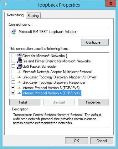
Outlook Client Protocols
MAPI over HTTPS - Outlook 2013 SP1 minimum
RPC over HTTPS - aka Outlook Anywhere
Mail Flow
In Exchange Server 2019, mail flow occurs through the transport pipeline. The transport pipeline is a collection of
services, connections, components, and queues that work together to route all messages to the categorizer in the
Transport service on an Exchange 2019 Mailbox server. For more information please refer to the following
Microsoft link: https://docs.microsoft.com/en-us/Exchange/mail-flow/mail-flow?redirectedfrom=MSDN&
view=exchserver-2019
7. Load Balancing Exchange 2019
It’s highly recommended that you have a working Exchange 2019 environment first before
Note
implementing the load balancer.
Load Balancing & HA Requirements
Load balancing requirements for Exchange 2019 are the same as those for Exchange 2016. There is a single
building block that provides the client access services and the high availability architecture necessary for any
enterprise messaging environment. High availability is provided by implementing multiple Mailbox Servers,
configuring a Database Availability Group (DAG) and deploying a load balancer.
Database Availability Group (DAG)
A DAG is a group of up to 16 Mailbox Servers with 100 active and passive databases. It provides automatic
database-level recovery from failures that affect individual servers or databases.
DAGs utilize Microsoft Clustering Services which cannot be enabled on the same server as
Note Microsoft Network Load Balancing (NLB). Therefore, using Microsoft NLB is not an option in this
case. Using a Loadbalancer.org hardware or virtual appliance provides an ideal solution.
Persistence (aka Server Affinity)
As with Exchange 2016, Exchange 2019 does not require session affinity at the load balancing layer.
Port Requirements
The following table shows the port list that must be load balanced. Some services such as IMAP4 or POP3 may not
be required in your environment.
TCP Port Role Uses
25 MBOX Inbound SMTP
110 MBOX POP3 clients
143 MBOX IMAP4 clients
5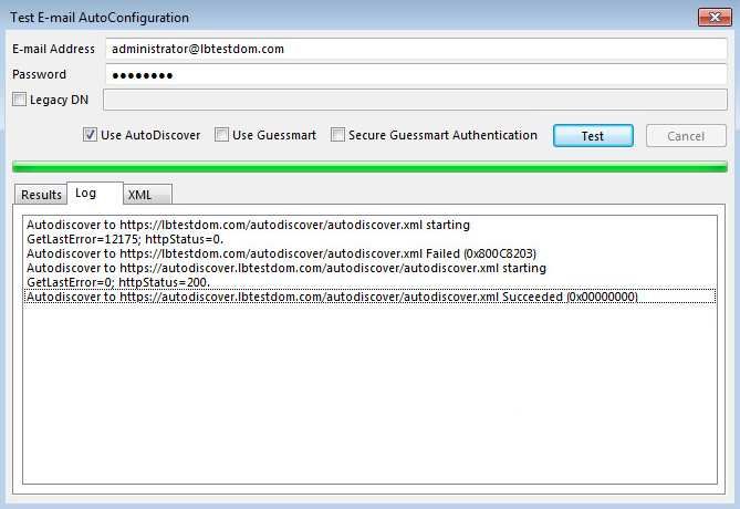
TCP Port Role Uses
443 MBOX HTTPS (Outlook on the Web,
AutoDiscovery, Web Services,
ActiveSync, MAPI over HTTP, RPC
over HTTP – a.k.a. Outlook
Anywhere, Offline Address Book,
Exchange Administration Center)
993 MBOX Secure IMAP4 clients
995 MBOX Secure POP3 clients
SSL Termination
We generally recommend that SSL is terminated on the Exchange servers for scalability and effective load sharing.
However, if you’re load balancing Exchange using layer 7 SNAT mode, by default, the client IP address will be lost
and replaced by the load balancer’s own IP and therefore audit logs will contain the load balancer’s IP address and
not the clients. If this is an issue for your environment, X-Forwarded-For headers can be inserted by the load
balancer which enable IIS on each Exchange server to be configured to log the client address from the XFF header
as described in this Microsoft article. In this case, SSL must be terminated on the load balancer to allow the header
to be inserted. Once inserted, traffic can be re-encypted from the load balancer to the Exchange servers. For more
details on configuring layer 7 SNAT mode with SSL offload, please refer to Appliance Configuration – Using Layer 7
SNAT Mode (with SSL Offload).
HTTPS Namespaces & IP addresses
The following examples show 2 different approaches to HTTPS namespace configuration and the related load
balancing considerations for each.
Example 1 – simple namespace configuration
Namespace Purpose
mail.lbtestdom.com Outlook on the Web, ActiveSync, MAPI over HTTP, RPC
over HTTP, Offline Address Book, Exchange Web
Services
autodiscover.lbtestdom.com Auto Discover
Notes:
In this case a single VIP is used for all HTTPS namespaces/services
Both DNS entries should then point at the same VIP
This method is simple to setup, but only permits a single Exchange URL to be health checked. However, a
successful full HTTPS service check on the OWA virtual directory is a good indication that the other Virtual
Directories & applications are also functioning correctly
Example 2 – expanded namespace configuration
Namespace Purpose
owa.lbtestdom.com Outlook on the Web
6 6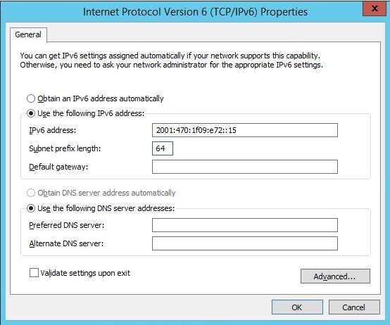
Namespace Purpose
outlook.lbtestdom.com Outlook Anywhere
ews.lbtestdom.com Exchange Web Services
autodiscover.lbtestdom.com Autodiscover
activesync.lbtestdom.com ActiveSync
oab.lbtestdom.com Offline Address Book
Notes:
In this case multiple VIPs are used – one for each HTTPS namespace/service
Each related DNS entry should then point at the corresponding VIP
This method is more complex to setup, but does enable more granular health checks to be configured
This guide uses the config of example 1 above, i.e. a single IP address for all services.
Health-Checks
In this guide, the health check for HTTPS services accesses owa/healthcheck.htm on each server and checks for a
'200 OK' response. A different virtual directory (e.g. ECP, EWS etc.) can be chosen if preferred or more appropriate.
Note that healthcheck.htm is generated in-memory based on the component state of the protocol in question and
does not physically exist on disk.
Load Balancer Deployment Concept
Exchange 2019 can be deployed in various ways, in this example two servers are used. Each server hosts the
Mailbox role in a DAG configuration. This provides high availability and uses a minimum number of Exchange
Servers.
Clients then connect to the Virtual Services (VIPs) on the load balancer rather than connecting directly to one of the
Exchange servers. These connections are then load balanced across the Exchange servers to distribute the load
according to the load balancing algorithm selected.
VIP = Virtual IP Addresses
7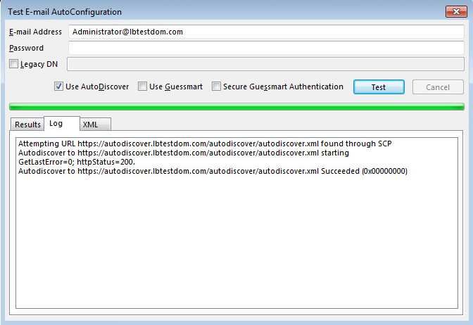
The load balancer can be deployed as a single unit, although Loadbalancer.org recommends a
Note clustered pair for resilience & high availability. Please refer to Configuring HA - Adding a Slave
Appliance for more details on configuring a clustered pair.
Virtual Service (VIP) Requirements
To provide load balancing and HA for Exchange 2019, the following VIPs are required:
HTTPS (for all HTTPS based services)
SMTP
Optionally, additional VIPs may be required as follows:
HTTP (for redirecting to HTTPS, please refer to Using a Layer 4 Virtual Service for SMTP for more details)
IMAP4
POP3
Note IMAP4 and POP3 are not typically used. Therefore these VIPs are not generally required.
Load Balancer Deployment Modes
The load balancer can be deployed in 4 fundamental ways: Layer 4 DR mode, Layer 4 NAT mode, Layer 4 SNAT
mode and Layer 7 SNAT mode.
For Exchange 2019, either layer 7 SNAT mode or layer 4 DR are normally used. These modes are described below
and are used for the configurations presented in this guide.
Layer 7 SNAT Mode
Layer 7 SNAT mode uses a proxy (HAProxy) at the application layer. Inbound requests are terminated on the load
balancer, and HAProxy generates a new request to the chosen Real Server. As a result, Layer 7 is a slower
technique than DR or NAT mode at Layer 4. Layer 7 is typically chosen when either enhanced options such as SSL
termination, cookie based persistence, URL rewriting, header insertion/deletion etc. are required, or when the
network topology prohibits the use of the layer 4 methods.
This mode can be deployed in a one-arm or two-arm configuration and does not require any changes to the Real
Servers. However, since the load balancer is acting as a full proxy it doesn’t have the same raw throughput as the
layer 4 methods.
The load balancer proxies the application traffic to the servers so that the source of all traffic becomes the load
balancer.
8 8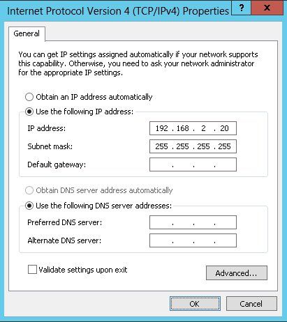
Layer 7 SNAT mode is a full proxy and therefore load balanced Real Servers do not need to be changed in any
way.
Because layer 7 SNAT mode is a full proxy any server in the cluster can be on any accessible subnet including
across the Internet or WAN.
Layer 7 SNAT mode is not transparent by default, i.e. the Real Servers will not see the source IP address of the
client, they will see the load balancer’s own IP address by default, or any other local appliance IP address if
preferred (e.g. the VIP address). This can be configured per layer 7 VIP. If required, the load balancer can be
configured to provide the actual client IP address to the Real Servers in 2 ways. Either by inserting a header
that contains the client’s source IP address, or by modifying the Source Address field of the IP packets and
replacing the IP address of the load balancer with the IP address of the client. For more information on these
methods please refer to Transparency at Layer 7.
Layer 7 SNAT mode can be deployed using either a 1-arm or 2-arm configuration.
You should not use the same RIP:PORT combination for layer 7 SNAT mode VIPs and layer 4 SNAT mode VIPs
because the required firewall rules conflict.
Layer 4 DR Mode
One-arm direct routing (DR) mode is a very high performance solution that requires little change to your existing
infrastructure.
Note Kemp, Brocade, Barracuda & A10 Networks call this Direct Server Return and F5 call it N-Path.
9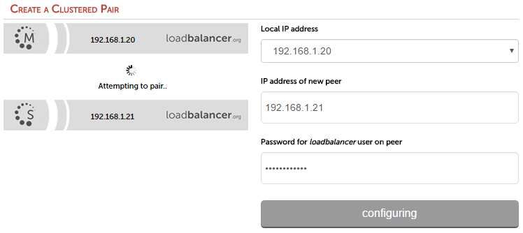
DR mode works by changing the destination MAC address of the incoming packet to match the selected Real
Server on the fly which is very fast.
When the packet reaches the Real Server it expects the Real Server to own the Virtual Services IP address
(VIP). This means that you need to ensure that the Real Server (and the load balanced application) respond to
both the Real Server’s own IP address and the VIP.
The Real Servers should not respond to ARP requests for the VIP. Only the load balancer should do this.
Configuring the Real Servers in this way is referred to as Solving the ARP Problem. For more information
please refer to DR Mode Considerations.
On average, DR mode is 8 times quicker than NAT for HTTP, 50 times quicker for Terminal Services and much,
much faster for streaming media or FTP.
The load balancer must have an Interface in the same subnet as the Real Servers to ensure layer 2
connectivity required for DR mode to work.
The VIP can be brought up on the same subnet as the Real Servers, or on a different subnet provided that the
load balancer has an interface in that subnet.
Port translation is not possible in DR mode i.e. having a different RIP port than the VIP port.
DR mode is transparent, i.e. the Real Server will see the source IP address of the client.
Our Recommendation
For simplicity we recommend using layer 7 SNAT mode. This mode requires no changes to the Exchange Servers
and enables the Exchange Servers to be located on any route-able network.
Is SSL Offloading Required?
We generally recommend that SSL is terminated on the Exchange servers for scalability and effective load sharing.
However, when using layer 7 SNAT mode, by default the client IP address is lost and is replaced by the load
balancer’s own IP address. Therefore, Exchange audit logs contain the load balancer’s IP address and not the
clients.
If this is an issue for your environment, X-Forwarded-For headers can be inserted by the load balancer which then
enables IIS on each Exchange server to be configured to log the client address – for more information, please refer
to this Microsoft article. To allow the header to be inserted, SSL must be terminated on the load balancer. Once
inserted, traffic is re-encypted from the load balancer to the Exchange Servers.
10 10
To configure the appliance using Layer 7 SNAT mode without SSL termination, refer to Appliance
Configuration – Using Layer 7 SNAT Mode (without SSL Offload).
For configuring appliance using Layer 7 SNAT mode with SSL termination, refer to Appliance Configuration –
Using Layer 7 SNAT Mode (with SSL Offload).
System Administrators typically want to lock down a receive connector to accept SMTP
connections only from a controlled set of devices such as external smart mail hosts, printers,
networked photocopiers etc. However, when using layer 7 SNAT mode - which is not transparent,
this is not possible. Instead, we recommend using the load balancer’s built in firewall to configure
SMTP lockdown as described in Configuring Firewall Rules to Lockdown SMTP.
Other Options:
Note 1 - Configure a layer 4 VIP for SMTP rather than a layer 7 based VIP. Layer 4 is transparent by
default so the source IP address is maintained. This is covered in Using a Layer 4 Virtual Service
for SMTP. This requires the ARP problem to be solved – this requires loopback adapters to be
installed on each Exchange Server and also modification to each servers strong / weak host
model.
2 - Enable full layer 7 transparency using TProxy. This is covered in Enabling Layer 7
Transparency using TProxy. This requires the load balancer to be deployed in a 2-arm
configuration where the load balancer becomes the default gateway for the Exchange Servers.
8. Configuring Exchange 2019 for Load Balancing
1) External Access Domain
This can be configured using the EAC. Select servers > virtual directories and then click the spanner icon. This will
open the form shown below. All Mailbox Servers should be configured with a valid external name, e.g.
mail.lbtestdom.com
112) Virtual Directories The Internal and External URL’s for the various virtual directories need to be configured to suit your environment. The External URL’s are automatically set to be the same as the external access domain when this is configured, but can be changed if needed. The Internal URL’s must be set individually by clicking the Edit (pen) icon for each virtual directory. All settings can be configured using the EAC option: servers > virtual directories as shown below: 3) Outlook Anywhere This is configured using the EAC. Select servers > servers and then click the edit (pen) icon next to each sever, click the Outlook Anywhere option as shown below to change the setting. The external and internal names for each server should be configured as required, e.g. mail.lbtestdom.com 12 12
4) Autodiscover
Internal

The Service Connection Point (SCP) object contains the authoritative list of Autodiscover service URLs for the
forest. The Set-ClientAccessService cmdlet can be used to update the SCP object as shown in the following
example:

  Set-ClientAccessService -Identity "EXCHANGE2019-1" -AutoDiscoverServiceInternalUri
  "https://autodiscover.lbtestdom.com/autodiscover/autodiscover.xml"

Once configured, the Test Email AutoConfiguration option available when  right-clicking the Outlook icon in
the taskbar can be used to view these settings as shown below:

              The minimum Outlook client for Exchange 2019 is Outlook 2010 with the latest service packs and
   Note
              updates.

                                                                                                                 13
External When Outlook is started on a client that is not domain-connected, it first tries to locate the Autodiscover service by looking up the SCP object in Active Directory. Because the client is unable to contact Active Directory, it tries to locate the Autodiscover service by using DNS. In this scenario, the client will determine the domain of the user’s e- mail address, and then check DNS by using two predefined URLs. For the SMTP domain lbtestdom.com, Outlook will try the following two URLs to try to connect to the Autodiscover service: https://lbtestdom.com/autodiscover/autodiscover.xml https://autodiscover.lbtestdom.com/autodiscover/autodiscover.xml Again, this can be seen using the Test Email AutoConfiguration option as shown below: 14 14
5) Certificates
The recommended approach is to use SAN certificates and specify all required namespaces. It’s also possible to
use wildcard certs if preferred. Certificate requests can be generated using either the graphical based Exchange
Admin Center or the command based Exchange Management Shell.

The EAC can also be used to import/export certificates using the server > certificates > More option

   Important       The same certificate and private key must be deployed on all Exchange Servers

6) Send & Receive Connectors
By default no send connectors are created when Exchange 2019 is installed. A send connector must be created
manually that either sends outbound email messages to a smart host or directly to their recipient using DNS.

Five receive connectors are automatically created by default. The table below lists these connectors:

Receive Connector                      Role                                   Purpose
Default                   MBOX                                   Accepts connections from Mailbox
                                                                              servers running the Transport
                                                                              service and from Edge servers
Client Proxy              MBOX                                   Accepts connections from front-end
                                                                              servers. Typically, messages are sent
                                                                              to a front-end server over SMTP
Default FrontEnd          MBOX                                   Accepts connections from SMTP
                                                                              senders over port 25. This is the
                                                                              common messaging entry point into
                                                                              your organization

                                                                                                                   15
Receive Connector Role Purpose
Outbound Proxy Frontend Connector on a back-end server,
with front-end proxy enabled
Client Frontend MBOX Accepts secure connections, with
Transport Layer Security (TLS)
applied
For more information on mail connectors please refer to the following Technet article:
https://technet.microsoft.com/en-us/library/jj657461(v=exchg.160).aspx
Adding Connectors
Connectors can be created using the Exchange Administration Center (EAC) or the Exchange Management Shell.
Receive connectors must use a unique combination of IP address bindings, port number assignments, and remote
IP address ranges from which mail is accepted. Multiple send connectors can created, this is typically done to
enables multiple outbound email routes to be specified that have different costs.
The exact connector configuration depends on your specific environment and requirements.
7) DNS Configuration
Configure appropriate internal and external DNS entries for the various Internal and External URL’s that have been
defined in steps 1) to 4). The DNS entries should point at the HTTPS VIP on the load balancer - assuming a simple
namespace design as shown below:
DNS record Purpose
mail.lbtestdom.com Points at the VIP used for all HTTPS based services
autodiscover.lbtestdom.com Points at the VIP used for all HTTPS based services
If multiple VIPs are defined for the various Virtual Directories, DNS should be configured
Note
accordingly.
8) Additional Exchange Server Configuration Steps (depends on Load balancing
method)
The steps required depend on the load balancing mode used as described below.
Layer 7 SNAT Mode
When using SNAT mode, no additional configuration changes to the Exchange Servers are required.
Layer 4 DR Mode
The 'ARP problem' must be solved on each Exchange Server for DR mode to work. For detailed steps on solving
the ARP problem for Windows 2019, please refer to Solving the ARP Problem.
16 169) IIS Restart (Important)
Once all Exchange configuration is complete restart IIS on each server (or reboot the server) to ensure all changes
are applied. This can be done using the following command in a command or Powershell Window:
iisreset /restart
9. Loadbalancer.org Appliance – the Basics
Virtual Appliance
A fully featured, fully supported 30 day trial is available if you are conducting a PoC (Proof of Concept) deployment.
The VA is currently available for VMware, Virtual Box, Hyper-V, KVM, XEN and Nutanix AHV and has been
optimized for each Hypervisor. By default, the VA is allocated 1 CPU, 2GB of RAM and has a 20GB virtual disk. The
Virtual Appliance can be downloaded here.
The same download is used for the licensed product, the only difference is that a license key file
Note (supplied by our sales team when the product is purchased) must be applied using the
appliance’s WebUI.
Please refer to The Virtual Appliance - Hypervisor Deployment and the ReadMe.txt text file
Note included in the VA download for more detailed information on deploying the VA using various
Hypervisors.
For the VA, 4 NICs are included but only eth0 is connected by default at power up. If the other
Note NICs are required, these should be connected using the network configuration screen within the
Hypervisor.
Initial Network Configuration
After boot up, follow the instructions on the console to configure the IP address, subnet mask, default gateway,
DNS and other network settings.
Be sure to set a secure password for the load balancer, when prompted during the setup
Important
routine.
Accessing the WebUI
The WebUI is accessed using a web browser. Appliance authentication is based on Apache .htaccess files. User
admin tasks such as adding users and changing passwords can be performed using the WebUI menu option:
Maintenance > Passwords.
A number of compatibility issues have been found with various versions of Internet Explorer. The
Note
WebUI has been tested and verified using both Chrome & Firefox.
If required, users can also be authenticated against LDAP, LDAPS, Active Directory or Radius. For
Note
more information please refer to External Authentication.
171. Using a browser, access the WebUI using the following URL:
https://:9443/lbadmin/
2. Log in to the WebUI:
Username: loadbalancer
Password:
Note To change the password, use the WebUI menu option: Maintenance > Passwords.
Once logged in, the WebUI will be displayed as shown below:
18 18The WebUI for the VA is shown, the hardware and cloud appliances are very similar. The
Note
yellow licensing related message is platform & model dependent.
3. You’ll be asked if you want to run the Setup Wizard. If you click Accept the Layer 7 Virtual Service
configuration wizard will start. If you want to configure the appliance manually, simple click Dismiss.
Main Menu Options
System Overview - Displays a graphical summary of all VIPs, RIPs and key appliance statistics
Local Configuration - Configure local host settings such as IP address, DNS, system time etc.
Cluster Configuration - Configure load balanced services such as VIPs & RIPs
Maintenance - Perform maintenance tasks such as service restarts and taking backups
View Configuration - Display the saved appliance configuration settings
Reports - View various appliance reports & graphs
Logs - View various appliance logs
Support - Create a support download, contact the support team & access useful links
HA Clustered Pair Configuration
Loadbalancer.org recommend that load balancer appliances are deployed in pairs for high availability. In this guide
a single unit is deployed first, adding a secondary slave unit is covered in Configuring HA - Adding a Slave
Appliance.
10. Appliance Configuration – Using Layer 7 SNAT Mode (without SSL
Offload)
Load Balancer Deployment Overview
The diagram below illustrates how the load balancer is configured and deployed.
Notes:
Layer 7 is not transparent by default. This means that the client source IP address is lost and is replaced by the
19IP address of the load balancer. All Exchange audit logs will show the IP address of the load balancer, not the
clients. If this is an issue, please refer to the configuration option in Appliance Configuration – Using Layer 7
SNAT Mode (with SSL Offload) where X-Forwarded-For headers are used to record the client IP address in the
Exchange server’s IIS logs.
System Administrators typically want to lock down a receive connector to accept SMTP connections only from
a controlled set of devices such as external smart mail hosts, printers, networked photocopiers etc. However,
when using layer 7 SNAT mode - which is not transparent, this is not possible. Instead, we recommend using
the load balancer’s built in firewall to configure SMTP lockdown as described in Configuring Firewall Rules to
Lockdown SMTP.
Other Options:
1 - Configure a layer 4 VIP for SMTP rather than a layer 7 based VIP. Layer 4 is transparent by default so the source
IP address is maintained. This is covered in Using a Layer 4 Virtual Service for SMTP. This requires the ARP
problem to be solved – this requires loopback adapters to be installed on each Exchange Server and also
modification to each servers strong / weak host model.
2 - Enable full layer 7 transparency using TProxy. This is covered in Enabling Layer 7 Transparency using TProxy.
This requires the load balancer to be deployed in a 2-arm configuration where the load balancer becomes the
default gateway for the Exchange Servers.
Load Balancer Configuration
Configure VIP1 – Mailbox Server Role HTTPS Services
a) Setting up the Virtual Service
1. Using the WebUI, navigate to: Cluster Configuration > Layer 7 – Virtual Service and click Add a New Virtual
Service
2. Enter the following details:
3. Enter an appropriate label for the VIP, e.g. MBOX-HTTPS
4. Set the Virtual Service IP address field to the required IP address, e.g. 192.168.30.10
5. Set the Virtual Service Ports field to 443
6. Set Layer 7 Protocol set to TCP Mode
7. Click Update
20 208. Now click Modify next to the newly created VIP
9. Set Balance mode to Weighted Round Robin
Microsoft recommends that 'Round Robin' rather than 'Least Connection' should be used to
help prevent over loading servers when they are brought online. This could occur if Least
Connection was selected, since the load balancer would try to balance the number of
Note
connections across all real severs and therefore send all new requests to the new server.
The trade off here is that using Round Robin will mean that server load may remain
unbalanced for some time after bringing a new server into the active pool.
10. Scroll down to the Persistence section and set Persistence Mode to None
11. In the Health Checks section set Health Checks to Negotiate HTTPS (GET)
12. Set Request to send to owa/healthcheck.htm
As mentioned earlier, any other Exchange virtual directory (e.g. ECP, EWS etc.) can be used
if preferred or more appropriate. All have an associated healthcheck.htm that can be used in
Note
the same way. Note that healthcheck.htm is generated in-memory based on the component
state of the protocol in question and does not physically exist on disk.
13. Leave Response expected blank, this will configure the load balancer to look for a '200 OK' response
14. Scroll down to the Other section and click [Advanced]
15. Enable (check) the Timeout checkbox and set both Client Timeout & Real Server Timeout to 30m (i.e. 30
minutes)
16. Click Update
b) Setting up the Real Servers
1. Using the WebUI, navigate to: Cluster Configuration > Layer 7 – Real Servers and click Add a new Real Server
next to the newly created VIP**
2. Enter the following details:
3. Enter an appropriate label for the RIP, e.g. MBOX1
4. Change the Real Server IP Address field to the required IP address, e.g. 192.168.30.20
5. Change the Real Server Port field to 443
6. Click Update
217. Repeat the above steps to add your other Mailbox Server(s)
c) Configure HTTP to HTTPS OWA Redirect
If required, the load balancer can be configured to automatically redirect users who attempt to connect to
http:// to https://. For details on configuring this, please refer to
Configuring an HTTP to HTTPS redirect for OWA.
Configure VIP2 – Mailbox Server Role IMAP4/POP3 Services
a) Setting up the Virtual Service
These steps show IMAP4 settings, for POP3 change the port numbers from 143 & 993 to 110 &
Note
995.
1. Using the WebUI, navigate to: Cluster Configuration > Layer 7 – Virtual Service and click Add a New Virtual
Service
2. Enter the following details:
3. Enter an appropriate label for the VIP, e.g. MBOX-IMAP4
4. Set the Virtual Service IP address field to the required IP address, e.g. 192.168.30.10
5. Set the Virtual Service Ports field to 143,993
6. Set Layer 7 Protocol to TCP Mode
7. Click Update
8. Now click Modify next to the newly created VIP
9. Set Balance mode to Weighted Round Robin
Microsoft recommends that 'Round Robin' rather than 'Least Connection' should be used to
help prevent over loading servers when they are brought online. This could occur if Least
Connection was selected, since the load balancer would try to balance the number of
Note
connections across all real severs and therefore send all new requests to the new server.
The trade off here is that using Round Robin will mean that server load may remain
unbalanced for some time after bringing a new server into the active pool.
22 2210. Scroll down to the Persistence section and set Persistence Mode to None
11. Scroll down to the Other section and click [Advanced]
12. Enable (check) the Timeout checkbox and set both Client Timeout & Real Server Timeout to 30m (i.e. 30
minutes)
13. Click Update
b) Setting up the Real Servers
1. Using the WebUI, navigate to: Cluster Configuration > Layer 7 – Real Servers and click Add a new Real Server
next to the newly created VIP**
2. Enter the following details:
3. Enter an appropriate label for the RIP, e.g. MBOX1
4. Change the Real Server IP Address field to the required IP address, e.g. 192.168.30.20
5. Leave the Real Server Port field blank
6. Click Update
7. Repeat the above steps to add your other Mailbox Server(s)
Configure VIP3 – Mailbox Server Role SMTP Services
a) Setting up the Virtual Service
1. Using the WebUI, navigate to: Cluster Configuration > Layer 7 – Virtual Service and click Add a New Virtual
Service
2. Enter the following details:
233. Enter an appropriate label for the VIP, e.g. MBOX-SMTP
4. Set the Virtual Service IP address field to the required IP address, e.g. 192.168.30.10
5. Set the Virtual Service Ports field to 25
6. Set Layer 7 Protocol to TCP Mode
7. Click Update
8. Now click Modify next to the newly created VIP
9. Scroll down to the Persistence section and set Persistence Mode to None
10. Scroll down to the Other section and click [Advanced]
11. Enable (check) the Timeout checkbox and set both Client Timeout & Real Server Timeout to 30m (i.e. 30
minutes)
12. Click Update
b) Setting up the Real Servers
1. Using the WebUI, navigate to: Cluster Configuration > Layer 7 – Real Servers and click Add a new Real Server
next to the newly created VIP**
2. Enter the following details:
3. Enter an appropriate label for the RIP, e.g. MBOX1
4. Change the Real Server IP Address field to the required IP address, e.g. 192.168.30.20
5. Change the Real Server Port field to 25
6. Click Update
7. Repeat the above steps to add your other Mailbox Server(s)
Configuring Firewall Rules to Lockdown SMTP
Because layer 7 is not transparent by default, it’s not possible to filter inbound SMTP connections by IP address at
the receive connector. Our recommended way to address this is to use the load balancer’s built-in firewall to
control which hosts can connect to the SMTP VIP on port 25. Please refer to Configuring Firewall Rules to
Lockdown SMTP for details of how to configure this.
Additional Settings if using Kerberos Authentication
If you’re using Kerberos to authenticate your Exchange users and these users are members of a large number of
AD security groups and/or have a large SID history, Kerberos tickets may become so large that they no longer fit in
the standard 16K HAProxy response buffer. For Windows 2012 and later, the default MaxTokenSize is set to 48K. In
24 24addition, there is a new KDC policy setting that can be enabled to log an event in the system event log if a
Kerberos ticket is larger than a certain size (the default setting is 12k). If you determine that tickets in your
environment are larger than 16K, the default response buffer size on the load balancer must be increased.
To increase the Request buffer size:
1. Go to Cluster Configuration > Layer 7 – Advanced Configuration
2. Set the Request buffer length to the required value, e.g. 51200 (i.e. 50K)
Finalizing the Configuration
To apply the new layer 7 configuration, HAProxy must be restarted using the WebUI option: Maintenance > Restart
Services and clicking Restart HAProxy
Exchange Server Configuration Steps
No additional configuration is required when SSL is terminated on the Exchange Servers.
11. Appliance Configuration – Using Layer 7 SNAT Mode (with SSL
Offload)
Load Balancer Deployment Overview
The diagram below illustrates how the load balancer is configured and deployed. The key difference to the
previous configuration is that SSL is terminated on the load balancer.
Notes:
Layer 7 is not transparent by default. This means that the client source IP address is lost and is replaced by the
IP address of the load balancer. To allow the client IP address to be passed to the Exchange Servers, SSL is
terminated on the load balancer which enables X-forwarded-For headers to be inserted. The Exchange
servers can then be configured so that this address is included in the IIS logs as described in this Microsoft
article.
System Administrators typically want to lock down a receive connector to accept SMTP connections only from
a controlled set of devices such as external smart mail hosts, printers, networked photocopiers etc. However,
when using layer 7 SNAT mode - which is not transparent, this is not possible. Instead, we recommend using
the load balancer’s built in firewall to configure SMTP lockdown as described in Configuring Firewall Rules to
25Lockdown SMTP .
Other Options:
1 - Configure a layer 4 VIP for SMTP rather than a layer 7 based VIP. Layer 4 is transparent by default so the source
IP address is maintained. This is covered in Using a Layer 4 Virtual Service for SMTP. This requires the ARP
problem to be solved – this requires loopback adapters to be installed on each Exchange Server and also
modification to each servers strong / weak host model.
2 - Enable full layer 7 transparency using TProxy. This is covered in Enabling Layer 7 Transparency using TProxy.
This requires the load balancer to be deployed in a 2-arm configuration where the load balancer becomes the
default gateway for the Exchange Servers.
Load Balancer Configuration
Configure VIP1 – Mailbox Server Role HTTPS Services
a) Setting up the Virtual Service
1. Using the WebUI, navigate to: Cluster Configuration > Layer 7 – Virtual Service and click Add a New Virtual
Service
2. Enter the following details:
3. Enter an appropriate label for the VIP, e.g. MBOX-HTTPS
4. Set the Virtual Service IP address field to the required IP address, e.g. 192.168.30.10
5. Set the Virtual Service Ports field to 80
6. Set Layer 7 Protocol set to HTTP Mode
7. Click Update
8. Now click Modify next to the newly created VIP
9. Set Balance mode to Weighted Round Robin
26 26Microsoft recommends that 'Round Robin' rather than 'Least Connection' should be used to
help prevent over loading servers when they are brought online. This could occur if Least
Connection was selected, since the load balancer would try to balance the number of
Note
connections across all real severs and therefore send all new requests to the new server.
The trade off here is that using Round Robin will mean that server load may remain
unbalanced for some time after bringing a new server into the active pool.
10. Scroll down to the Persistence section and set Persistence Mode to None
11. In the Health Checks section set Health Checks to Negotiate HTTPS (GET)
12. Set Request to send to owa/healthcheck.htm
As mentioned earlier, any other Exchange virtual directory (e.g. ECP, EWS etc.) can be used
if preferred or more appropriate. All have an associated healthcheck.htm that can be used in
Note
the same way. Note that healthcheck.htm is generated in-memory based on the component
state of the protocol in question and does not physically exist on disk.
13. Leave Response expected blank, this will configure the load balancer to look for a '200 OK' response
14. Scroll down to the Other section and click [Advanced]
15. Enable (check) the Timeout checkbox and set both Client Timeout & Real Server Timeout to 30m (i.e. 30
minutes)
16. Ensure that Set X-forwarded-For Header is enabled (checked)
17. Click Update
b) Setting up the Real Servers
1. Using the WebUI, navigate to: Cluster Configuration > Layer 7 – Real Servers and click Add a new Real Server
next to the newly created VIP**
2. Enter the following details:
3. Enter an appropriate label for the RIP, e.g. MBOX1
4. Change the Real Server IP Address field to the required IP address, e.g. 192.168.30.20
5. Change the Real Server Port field to 443
6. Enable (check) the Re-Encrypt to Backend checkbox
277. Click Update
8. Repeat the above steps to add your other Mailbox Server(s)
c) Export Your SSL Certificate
When you export your certificate from Exchange, make sure that your include the private key.
d) Upload Your SSL Certificate to The Load Balancer
To upload a Certificate:
1. Using the WebUI, navigate to: Cluster Configuration > SSL Certificates
2. Click *Add a new SSL Certificate *& select Upload prepared PEM/PFX file
3. Enter a suitable _Label _(name) for the certificate, e.g. ExchangeCert
4. Browse to and select the certificate file to upload (PEM or PFX format)
5. Enter the password , if applicable
6. Click Upload Certificate, if successful, a message similar to the following will be displayed:
e) Configure SSL Termination
To configure an SSL VIP:
1. Using the WebUI, navigate to: Cluster Configuration > SSL Termination and click *Add a new Virtual Service*
2. Enter a suitable Label (name) for the VIP, e.g. MBOX-SSL
3. Set Associated Virtual Service to the appropriate VIP, e.g. MBOX-HTTP
28 284. Select the SSL Certificate uploaded previously
5. Click Update
f) Configure HTTP to HTTPS OWA Redirect
If required, the load balancer can be configured to automatically redirect users who attempt to connect to
http:// to https://. For details on configuring this, please refer to
Configuring an HTTP to HTTPS redirect for OWA.
Configure VIP2 – Mailbox Server Role IMAP4/POP3 Services
a) Setting up the Virtual Service
These steps show IMAP4 settings, for POP3 change the port numbers from 143 & 993 to 110 &
Note
995.
1. Using the WebUI, navigate to: Cluster Configuration > Layer 7 – Virtual Service and click Add a New Virtual
Service
2. Enter the following details:
3. Enter an appropriate label for the VIP, e.g. MBOX-IMAP4
4. Set the Virtual Service IP address field to the required IP address, e.g. 192.168.30.10
5. Set the Virtual Service Ports field to 143,993
6. Set Layer 7 Protocol to TCP Mode
7. Click Update
8. Now click Modify next to the newly created VIP
9. Set Balance mode to Weighted Round Robin
Microsoft recommends that 'Round Robin' rather than 'Least Connection' should be used to
help prevent over loading servers when they are brought online. This could occur if Least
Connection was selected, since the load balancer would try to balance the number of
Note
connections across all real severs and therefore send all new requests to the new server.
The trade off here is that using Round Robin will mean that server load may remain
unbalanced for some time after bringing a new server into the active pool.
2910. Scroll down to the Persistence section and set Persistence Mode to None
11. Scroll down to the Other section and click [Advanced]
12. Enable (check) the Timeout checkbox and set both Client Timeout & Real Server Timeout to 30m (i.e. 30
minutes)
13. Click Update
b) Setting up the Real Servers
1. Using the WebUI, navigate to: Cluster Configuration > Layer 7 – Real Servers and click Add a new Real Server
next to the newly created VIP**
2. Enter the following details:
3. Enter an appropriate label for the RIP, e.g. MBOX1
4. Change the Real Server IP Address field to the required IP address, e.g. 192.168.30.20
5. Leave the Real Server Port field blank
6. Click Update
7. Repeat the above steps to add your other Mailbox Server(s)
Configure VIP3 – Mailbox Server Role SMTP Services
a) Setting up the Virtual Service
1. Using the WebUI, navigate to: Cluster Configuration > Layer 7 – Virtual Service and click Add a New Virtual
Service
2. Enter the following details:
30 303. Enter an appropriate label for the VIP, e.g. MBOX-SMTP
4. Set the Virtual Service IP address field to the required IP address, e.g. 192.168.30.10
5. Set the Virtual Service Ports field to 25
6. Set Layer 7 Protocol to TCP Mode
7. Click Update
8. Now click Modify next to the newly created VIP
9. Scroll down to the Persistence section and set Persistence Mode to None
10. Scroll down to the Other section and click [Advanced]
11. Enable (check) the Timeout checkbox and set both Client Timeout & Real Server Timeout to 30m (i.e. 30
minutes)
12. Click Update
b) Setting up the Real Servers
1. Using the WebUI, navigate to: Cluster Configuration > Layer 7 – Real Servers and click Add a new Real Server
next to the newly created VIP**
2. Enter the following details:
3. Enter an appropriate label for the RIP, e.g. MBOX1
4. Change the Real Server IP Address field to the required IP address, e.g. 192.168.30.20
5. Change the Real Server Port field to 25
6. Click Update
7. Repeat the above steps to add your other Mailbox Server(s)
Configuring Firewall Rules to Lockdown SMTP
Because layer 7 is not transparent by default, it’s not possible to filter inbound SMTP connections by IP address at
the receive connector. Our recommended way to address this is to use the load balancer’s built-in firewall to
control which hosts can connect to the SMTP VIP on port 25. Please refer to Configuring Firewall Rules to
Lockdown SMTP for details of how to configure this.
Additional Settings if using Kerberos Authentication
If you’re using Kerberos to authenticate your Exchange users and these users are members of a large number of
AD security groups and/or have a large SID history, Kerberos tickets may become so large that they no longer fit in
the standard 16K HAProxy response buffer. For Windows 2012 and later, the default MaxTokenSize is set to 48K. In
31addition, there is a new KDC policy setting that can be enabled to log an event in the system event log if a
Kerberos ticket is larger than a certain size (the default setting is 12k). If you determine that tickets in your
environment are larger than 16K, the default response buffer size on the load balancer must be increased.
To increase the Request buffer size:
1. Go to Cluster Configuration > Layer 7 – Advanced Configuration
2. Set the Request buffer length to the required value, e.g. 51200 (i.e. 50K)
Finalizing the Configuration
To apply the new layer 7 configuration, HAProxy must be restarted using the WebUI option: Maintenance > Restart
Services and clicking Restart HAProxy.
Exchange Server Configuration Steps
Configure IIS logging to Capture XFF Header IP Addresses
Please refer to this Microsoft article for configuration steps.
12. Appliance Configuration – Using Layer 4 DR Mode
Load Balancer Deployment Overview
The diagram below illustrates how the load balancer is configured and deployed.
Notes:
Layer 4 DR mode is transparent by default. This means that the client source IP address is maintained through
to the Exchange Servers & the audit logs.
When using DR mode, System Administrators are able to lock down the receive connector to accept SMTP
connections only from a controlled set of devices such as external smart mail hosts, printers, networked
photocopiers etc. As mentioned earlier, this is because DR mode is transparent, so source IP addresses are
preserved through the load balancer to the Exchange Servers.
32 32Load Balancer Configuration
Configure VIP1 – Mailbox Server Role HTTPS Services
a) Setting up the Virtual Service
1. Using the WebUI, navigate to: Cluster Configuration > Layer 4 – Virtual Service and click Add a New Virtual
Service
2. Enter the following details:
3. Enter an appropriate label for the VIP, e.g. MBOX-HTTPS
4. Set the Virtual Service IP address field to the required IP address, e.g. 192.168.30.10
5. Set the Virtual Service Ports field to 443
6. Leave Protocol set to TCP
7. Leave Forwarding Method set to Direct Routing
8. Click Update
9. Now click Modify next to the newly created VIP
10. Set Balance mode to Weighted Round Robin
Microsoft recommends that 'Round Robin' rather than 'Least Connection' should be used to
help prevent over loading servers when they are brought online. This could occur if Least
Connection was selected, since the load balancer would try to balance the number of
Note
connections across all real severs and therefore send all new requests to the new server.
The trade off here is that using Round Robin will mean that server load may remain
unbalanced for some time after bringing a new server into the active pool.
11. Un-check the Persistence option
12. Set Check Type to Negotiate
13. Set Protocol to HTTPS
14. Set Request to send to owa/healthcheck.htm
33You can also read