Instruction Z-Wave PC based Controller v5 User Guide - Silicon Labs
←
→
Page content transcription
If your browser does not render page correctly, please read the page content below
Instruction
 Z-Wave PC based Controller v5 User Guide

Document No.:            INS13114

Version:                 18

Description:             -

Written By:              JFR;SEROMAN1;SCBROWNI;VOSAVOST;OBOIKO

Date:                    2020-06-24
                         JKA;COLSEN;CRASMUSSEN;LTHOMSEN;JBU;JSI;ABUENDIA;RREYES;SEROMAN1;SCB
Reviewed By:
                         ROWNI;JFR
Restrictions:            Public

 Approved by:

 Date                CET              Initials Name                                       Justification
 2020-06-24          09:03:58         NTJ      Niels Johansen

This document is the property of Silicon Labs. The data contained herein, in whole or in
part, may not be duplicated, used or disclosed outside the recipient for any purpose. This
restriction does not limit the recipient's right to use information contained in the data if it
is obtained from another source without restriction.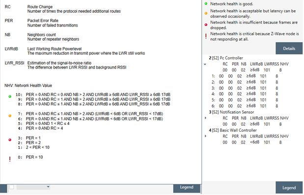
INS13114-18                          Z-Wave PC based Controller v5 User Guide                                      2020-06-24

                                                REVISION RECORD

   Doc.   Date       By            Pages affected        Brief description of changes
   Rev
   1      20141217   SRO;AVA;VSA   All                   Initial version based on INS10240-13
          20150226   SRO;AVA;VSA   All                   Updated all screenshots,
                                                         Updated Association, Command Class, Encrypt/Decrypt, Firmware
                                                         Update, Backup/Restore NVM topics
                                                         Added IMA, Settings Trace Capturing, Polling functionality, Setup
                                                         Route functionality topic
          20150226   SRO           4.20.1                Added Power shell script example
   2      20160128   SRO;VSA       All                   Update all screenshots
                                   3.1.1                 Added new settings view
                                                         Updated description for Security S0 test settings and added
                                                         description for Security S2 keys and test settings
                                   0                     Update list of views available from start screen
                                   3.2                   Described ‘Floating View’ option
                                   3.2.3                 Added screenshot for additional Bridge Controller actions (Add,
                                                         Remove virtual)
                                                         Updated description of the available nodes’ actions including
                                                         Security S2-related actions
                                   3.2.4                 Added screenshot for additional Bridge Controller action (Slave
                                                         Learn Mode)
                                                         Updated description of the available controller actions
                                                         Added description of the Set Node Information action.
                                   3.4                   Updated description of the available options on the Command
                                                         Classes view
                                   3.10                  Added Security S2 Encrypt/Decrypt description
                                   3.14, 4.15            Added: Configuration Command Class support
                                   3.15,                 Added: UL Monitor Tool
                                   4.1                   Update Table1
                                   4.2.2                 Added: Nodes with Endpoints
                                   4.2.5                 Added: NWE
                                   4.2.10                Added warning screenshot if SIS already present in network
                                   4.2.22                Added: Select Security scheme
                                   4.2.20                Added: Reset SPAN
   3      20160224   SRO           All                   Update all screenshots
                                   3.1.1                 Updated: Settings also contains connection args input field
                                   4.2.1                 Changed: added secure S2 node inclusion dialogs description
   4      20160708   SRO           3.1.1                 Updated Tab S2 Security Test Scheme topic (new test settings and
                                                         CSA option)
                                   3.2                   Updated screenshot
                                   3.2.4                 Updated screenshot and added MPAN table description
                                   3.3                   Updated Association view screenshot and description
                                   3.1, 3.2, 3.2.3       Added screenshots for Z/IP controller
                                   3.2.4                 Added screenshots for Z/IP controller, Unsolicited destination
                                                         description
          20160708   SRO           4.5                   Updated topic
   5      20160726   AVASILEVSKY   4, 4.2.1              Added reminders to set up unsolicited destination for Z/IP Gateway
          20160726   AVASILEVSKY   3.4                   Update command classes view screenshot
                                                         Added description of ‘Auto increment’ session id functionality for
                                                         supervision encapsulation
          20160805   AVASILEVSKY   4.14                  Added clarifications on how NVM restores from zip and hex files
   6      20160912   AVASILEVSKY   3.1, 3.2, 3.11, 4.2   Updated screenshots
                                                         Added description for new buttons and views
          20160913   AVASILEVSKY   4.7                   Added explanations how to configure security test schema
          20160927   JFR           1.3                   Updated necessary tools for PC-based Controller build environment.
   7      20161206   SRO           2.3                   Updated installation steps

silabs.com | Building a more connected world.                                                                     Page ii of viii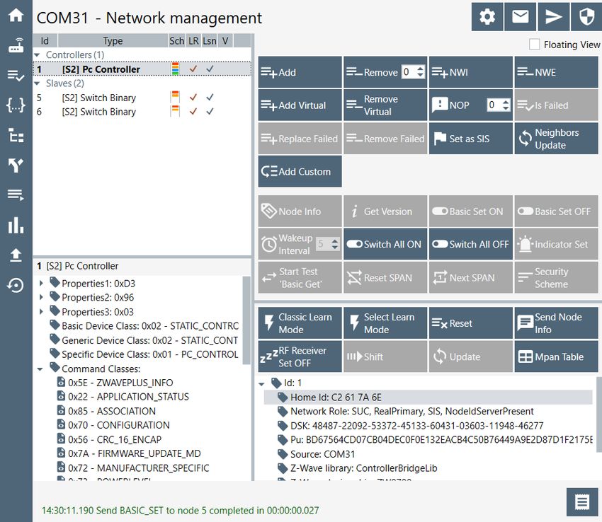
INS13114-18                             Z-Wave PC based Controller v5 User Guide                                       2020-06-24

                                                  REVISION RECORD

   Doc.   Date       By               Pages affected        Brief description of changes
   Rev
                                      All                   Updated screenshots
                                                            Removed “Start the Z-Wave PC Controller” section
                                      3.1.1.4               Updated section: Security Test Schema Button
          20161212   SRO              4.7                   Updated section: Security Test Schema view
                                      4.12                  Added S2 message encapsulation frame decrypt description
                                      4.14                  Include mention of the wake-up settings of the Sensor PIR nodes
   8      20170922   VSAVOSTIANENKO                         Removed image “Node settings pop-up window”
                                      3.1.1.4               Added property “Is Broadcast”
                                      4.7.2                 Added property “Is Broadcast” explanation
                                                            Removed “UL Tool Monitor View” section
                                                            Removed “UL Tool Monitor” Section
                                      3.15                  Added “Smart Start View” section
                                      4.16                  Added “Smart Start” section
                                      All                   Updated screenshots
                                      4.7.3                 Added description of “Applied Action” and updated examples
   9      20180305   BBR              All                   Added Silicon Labs template
   10     20180531   SRO              1.3                   Updated to .Net Framework 4.5
   11     20180601   VSAVOSTIANENKO   All                   Updated all screenshots
          20180601   VSAVOSTIANENKO   3.2.4                 Updated selection learn mode
          20180601   VSAVOSTIANENKO   3.4                   Added additional buttons
          20180601   VSAVOSTIANENKO   4.16                  Updated view description
          20190315   JFR              All                   Fixed page numbers
   12     20190320   AYurttas         All                   TechPub reviewed revision
   13     20190520   VOSAVOST         All                   Updated all screenshots
                                      3.2.3                 Added Identify button
                                      4.2.18                Added Identify button description
                                      3.16                  Added Transmit Settings UI
                                      4.17                  Added Transmit Settings UI description
          20190520   SEROMAN1         1.3 & 2.1             Updated sections
   14     20190523   SCBROWNI         2.1 & 4.17            Typos
   15     20190613   VOSAVOST         2.2                   Updated section “Required Z-Wave Hardware”
                                      3.16                  Updated screenshot and description table
                                      4.17                  Updated section “Transmit Settings” and screenshot
          20190621   VOSAVOST         4.3                   Remove Set Node Info from Controller View functionality section
                                      3.16                  Added section “Set Node Information View” section
                                      4.17                  Added section “Set Node Information” section
                                      4.1                   Updated table
   16     20190923   SEROMAN1         3.1.1.1               Updated table and figure
                                      3.1.1.3               Added Section
                                      All                   Updated Sections and screenshots
          20191203   VOSAVOST         3.1.1.1               Updated Table
                                      3.2.4                 Updated “unsolicited destination view” description
                                      All                   Updated screenshots
          20200326   VOSAVOST         All                   Added and updated List of tables and Indexes
          20200327   VOSAVOST         All                   Review changes, updated references and punctuation
   17     20200528   SCBROWNI         All                   Technical Publications Review
          20200603   VOSAVOST         4.5.1                 Fixed typo
   18     20200618   SEROMAN1         All                   Updated screenshots related to Long Range feature
                                      3.2.1, 3.15, 4.16     Added 'LR flag', added 'Node Options'

silabs.com | Building a more connected world.                                                                        Page iii of viii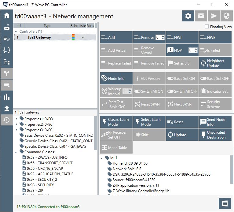
INS13114-18 Z-Wave PC based Controller v5 User Guide 2020-06-24
Table of Contents
1. ABBREVIATIONS............................................................................................................................1
1 INTRODUCTION ............................................................................................................................1
1.1 Purpose..............................................................................................................................................1
1.2 Audience and Prerequisites...............................................................................................................1
1.3 Implementation.................................................................................................................................1
2 THE Z-WAVE PC-BASED CONTROLLER............................................................................................2
2.1 Check the Prerequisites.....................................................................................................................2
2.2 Required Z-Wave Hardware ..............................................................................................................2
2.3 Install the Z-Wave PC Controller .......................................................................................................3
2.4 Remove Z-Wave PC Controller ..........................................................................................................3
3 USER INTERFACE ...........................................................................................................................4
3.1 Main Menu View ...............................................................................................................................4
3.1.1 Title Bar ...................................................................................................................................4
3.1.1.1 Settings...............................................................................................................................4
3.1.1.2 Commands Queue Button ..................................................................................................6
3.1.1.3 Send Data Settings..............................................................................................................6
3.1.1.4 Security Test Schema Button..............................................................................................7
3.1.2 Content View.........................................................................................................................11
3.1.3 Log Bar...................................................................................................................................13
3.2 Network Management View ...........................................................................................................14
3.2.1 Node List View.......................................................................................................................15
3.2.2 Node Information View.........................................................................................................16
3.2.3 Nodes Actions View...............................................................................................................16
3.2.4 Controller View .....................................................................................................................20
3.3 Associations View ............................................................................................................................24
3.4 Command Class View ......................................................................................................................25
3.5 Setup Route View ............................................................................................................................29
3.6 ERTT View ........................................................................................................................................31
3.7 Polling View .....................................................................................................................................32
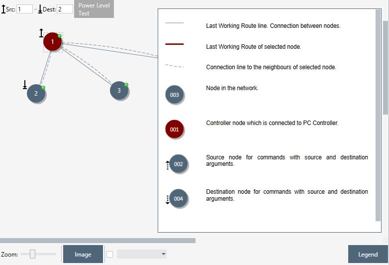
3.8 Topology Map View.........................................................................................................................32
3.9 IMA Network View ..........................................................................................................................34
3.10 Encrypt/Decrypt View .....................................................................................................................38
3.11 Firmware Update (OTA) View..........................................................................................................40
3.12 Firmware Update (OTW) View ........................................................................................................42
3.13 Backup/Restore NVM ......................................................................................................................42
3.14 Configuration Parameters ...............................................................................................................43
3.15 Smart Start View..............................................................................................................................43
3.16 Set Node Information View .............................................................................................................45
3.17 Transmit Settings View....................................................................................................................47
silabs.com | Building a more connected world. Page iv of viii
INS13114-18                                         Z-Wave PC based Controller v5 User Guide                                               2020-06-24

4     FUNCTIONALITY ..........................................................................................................................49
4.1 The SC Properties ............................................................................................................................50
4.2 Node View .......................................................................................................................................52
  4.2.1    How to Add a Node ...............................................................................................................52
  4.2.2    How to Add Multichannel Node with EndPoints...................................................................54
  4.2.3    How to Remove a Node ........................................................................................................54
  4.2.4    Network Wide Inclusion ........................................................................................................54
  4.2.5    Network Wide Exclusion .......................................................................................................55
  4.2.6    Send NOP ..............................................................................................................................55
  4.2.7    How to Send a Failure Signal to a Node ................................................................................55
  4.2.8    How to Replace a Failed Node ..............................................................................................55
  4.2.9    How to Remove a Failing Node .............................................................................................55
  4.2.10   Set SIS....................................................................................................................................56
  4.2.11   Request Node Neighbors Update..........................................................................................56
  4.2.12   Node Info...............................................................................................................................56
  4.2.13   Version Get............................................................................................................................56
  4.2.14   Switching a Node or a Subset of Nodes on and off ...............................................................56
  4.2.15   Set Wake-Up Interval ............................................................................................................57
  4.2.16   ‘Switch All On’ Command......................................................................................................57
  4.2.17   ‘Switch All Off’ Command .....................................................................................................57
  4.2.18   ‘Identify’ Command...............................................................................................................57
  4.2.19   Start/Stop Basic Test .............................................................................................................57
  4.2.20   Reset SPAN ............................................................................................................................57
  4.2.21   Next SPAN .............................................................................................................................57
  4.2.22   Security Scheme ....................................................................................................................57
4.3 Controller View................................................................................................................................58
  4.3.1    Reset Controller ....................................................................................................................58
  4.3.2    Send Node Info......................................................................................................................58
  4.3.3    Controller Shift ......................................................................................................................58
  4.3.4    Request Update of PC-based SC............................................................................................58
4.4 Command Class View ......................................................................................................................59
4.5 Association View..............................................................................................................................59
  4.5.1    Create Association.................................................................................................................59
  4.5.2    Remove Association ..............................................................................................................59
4.6 Setup Route View ............................................................................................................................59
  4.6.1    Assign a Route .......................................................................................................................59
  4.6.2    Delete a Route.......................................................................................................................60
4.7 Security Test Schema View..............................................................................................................60
  4.7.1    Test S2 Parameters Overrides ...............................................................................................60
  4.7.2    Test S2 Messages Overrides..................................................................................................61
  4.7.3    Test S2 Message Encapsulation Extensions Overrides..........................................................62
4.8 ERTT View ........................................................................................................................................63
4.9 Polling View .....................................................................................................................................65
4.10 Topology Map View.........................................................................................................................65
4.11 IMA Network View ..........................................................................................................................65

silabs.com | Building a more connected world.                                                                                             Page v of viii
INS13114-18 Z-Wave PC based Controller v5 User Guide 2020-06-24
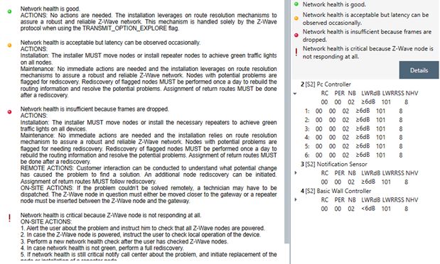
4.11.1 Network Health .....................................................................................................................66
4.11.2 Power Level Test ...................................................................................................................66
4.12 Security Encrypt/Decrypt ................................................................................................................66
4.13 Firmware Update.............................................................................................................................68
4.14 NVM Backup/Restore ......................................................................................................................68
4.15 Configuration Parameters ...............................................................................................................68
4.16 Smart Start ......................................................................................................................................69
4.17 Set Controller Node Information.....................................................................................................69
4.18 Transmit Settings.............................................................................................................................72
4.19 Z-Wave PC Controller Log................................................................................................................73
4.20 Settings Trace Capturing .................................................................................................................73
4.20.1 Open Saved Capture Trace File .............................................................................................73
5 REFERENCES................................................................................................................................76
INDEX ................................................................................................................................................77
List of Figures
Figure 1. PC with a Z-Wave Module Connected ..........................................................................................2
Figure 2. Main Menu View ..........................................................................................................................4
Figure 3. Settings View ................................................................................................................................5
Figure 4. Commands Queue View ...............................................................................................................6
Figure 5. Send Data Settings........................................................................................................................6
Figure 6. Security Test Settings....................................................................................................................8
Figure 7. Security Parameter Overrides.......................................................................................................9
Figure 8. Security Message Overrides .......................................................................................................10
Figure 9. Security Extension Overrides ......................................................................................................11
Figure 10. Content View ............................................................................................................................12
Figure 11. Content View with Z/IP Controller Connected .........................................................................13
Figure 12. Log Bar View .............................................................................................................................13
Figure 13. Log Window View .....................................................................................................................13
Figure 14. Network Management View.....................................................................................................14
Figure 15. Network Management View with Z/IP Controller Connected..................................................15
Figure 16. Nodes View...............................................................................................................................15
Figure 17. Node Information View ............................................................................................................16
Figure 18. Nodes Actions View ..................................................................................................................16
Figure 19. Nodes Actions View when Z/IP Controller Connected .............................................................17
Figure 20. Bridge Controller Additional Actions ........................................................................................17
Figure 21. Add Custom ..............................................................................................................................19
Figure 22. Controller View.........................................................................................................................20
Figure 23. Z/IP Controller View..................................................................................................................20
Figure 24. Select Learn Mode ....................................................................................................................20
Figure 25. Bridge Controller Additional Action..........................................................................................21
Figure 26. Mpan Table View ......................................................................................................................22
silabs.com | Building a more connected world. Page vi of viiiINS13114-18 Z-Wave PC based Controller v5 User Guide 2020-06-24 Figure 27. Unsolicited Destination View....................................................................................................23 Figure 28. Associations View .....................................................................................................................24 Figure 29. Command Classes View ............................................................................................................26 Figure 30. Select Command View ..............................................................................................................29 Figure 31. Setup Route View .....................................................................................................................29 Figure 32. ERTT View .................................................................................................................................31 Figure 33. Polling View ..............................................................................................................................32 Figure 34. Topology Map...........................................................................................................................33 Figure 35. IMA Network View....................................................................................................................34 Figure 36. IMA Network Health Status Description (Details) ....................................................................36 Figure 37. IMA Network Health Value Description (Legend).....................................................................37 Figure 38. IMA Nodes View Description (Legend) .....................................................................................38 Figure 39. Encrypt/Decrypt View S0 Tab ...................................................................................................39 Figure 40. Encrypt/Decrypt View S2 Tab ...................................................................................................39 Figure 41. Firmware Update (OTA) View...................................................................................................40 Figure 42. File Dialog View.........................................................................................................................42 Figure 43. NVM Backup/Restore View ......................................................................................................42 Figure 44. Configuration Parameters View................................................................................................43 Figure 45. Smart Start View .......................................................................................................................44 Figure 46. Z/IP Controller Connected Smart Start View ............................................................................44 Figure 47. Set Node Info View ...................................................................................................................46 Figure 48. Transmit Settings View .............................................................................................................47 Figure 49. Popup Message After Pressing 'Add' Button ............................................................................53 Figure 50. Network Keys Request..............................................................................................................53 Figure 51. Enter DSK Dialog .......................................................................................................................53 Figure 52. Multi Channel Node with End Points View ...............................................................................54 Figure 53. Popup Message After Pressing 'Remove' Button .....................................................................54 Figure 54. Set SIS Warning Message..........................................................................................................56 Figure 55. Select Security Scheme Dialog..................................................................................................57 Figure 56. Test Frame Configuration for Example 1 ..................................................................................61 Figure 57. Test Frame Configuration for Example 2 ..................................................................................62 Figure 58. Last Used Temp Key..................................................................................................................66 Figure 59. S2 Message Encapsulation Frame.............................................................................................66 Figure 60. S2 Message Encapsulation Frame Hex Data .............................................................................67 Figure 61. S2 Message Encapsulation Frame Decrypt ...............................................................................67 Figure 62. Provisioning List Item Delete Popup.........................................................................................69 Figure 63. Smart Start Added Device Locally Reset Popup........................................................................69 Figure 64. Set Node Information view.......................................................................................................70 Figure 65. Device options ..........................................................................................................................70 Figure 66. Generic options ........................................................................................................................71 Figure 67. Specific options.........................................................................................................................71 Figure 68. Role Types.................................................................................................................................72 Figure 69. Node Types ...............................................................................................................................72 Figure 70. Transmit Settings Tx Power Level .............................................................................................72 Figure 71. Select RF Region setting............................................................................................................73 silabs.com | Building a more connected world. Page vii of viii
INS13114-18                                        Z-Wave PC based Controller v5 User Guide                                               2020-06-24

                                                           List of Tables
Table 1. Settings View Items........................................................................................................................5
Table 2. Commands Queue View Items.......................................................................................................6
Table 3. Send Data Settings Items ...............................................................................................................7
Table 4. Security Test Settings View Items ..................................................................................................8
Table 5. Log View Items.............................................................................................................................14
Table 6. Node Actions View Items .............................................................................................................18
Table 7. Controller Actions View Items .....................................................................................................21
Table 8. General Information View Items..................................................................................................22
Table 9. MPAN View Items ........................................................................................................................23
Table 10. Unsolicited View Items ..............................................................................................................23
Table 11. Association View Items ..............................................................................................................25
Table 12. Send Data View Items ................................................................................................................27
Table 13. Select Command View Items .....................................................................................................29
Table 14. Setup Route View Items.............................................................................................................30
Table 15. ERTT View Items.........................................................................................................................31
Table 16. Polling View Items......................................................................................................................32
Table 17. Topology Map View Items .........................................................................................................33
Table 18. IMA Network View Items ...........................................................................................................35
Table 19. IMA Details View Items ..............................................................................................................36
Table 20. IMA Nodes View Items...............................................................................................................38
Table 21. Encrypt/Decrypt S0 View Items .................................................................................................39
Table 22. Encrypt/Decrypt S2 View Items .................................................................................................40
Table 23. Firmware Update OTA View Items.............................................................................................41
Table 24. NVM Backup/Restore View Items..............................................................................................43
Table 25. Configuration Parameters View Items .......................................................................................43
Table 26. Smart Start View Items ..............................................................................................................45
Table 27. Set Node Info View Items ..........................................................................................................47
Table 28. Transmit Settings View Items ....................................................................................................48
Table 29. Overview of the Static Controller Properties .............................................................................51

silabs.com | Building a more connected world.                                                                                          Page viii of viii
INS13114-18 Z-Wave PC based Controller v5 User Guide 2020-06-24 1. ABBREVIATIONS Abbreviation Explanation API Application Programming Interface DLL Dynamic Link Library IMA Installation and Maintenance Application NVM Non-volatile memory OTA Over-the-air OTW Over-the-wire SC Static Controller SUC Static Update Controller SIS SUC ID Server ERTT Enhanced Reliability Test Tool DSK Device-Specific Key LR Long Range 1 INTRODUCTION 1.1 Purpose The Z-Wave PC-based Controller application is an example on how Static/Bridge Controller Serial API functionality can be used to implement a Z-Wave-enabled PC application. 1.2 Audience and Prerequisites The audience is Z-Wave partners and Silicon Labs. It is assumed that the Z-Wave partner is already familiar with the current Z-Wave Developer's Kit. 1.3 Implementation The Z-Wave PC-based Controller application requires the .NET Framework 4.6.1 or higher. It’s based on the Z-Wave DLL. Note: See [4] Regarding a detailed description about the Z-Wave DLL. silabs.com | Building a more connected world. Page 1 of 77
INS13114-18                             Z-Wave PC based Controller v5 User Guide                 2020-06-24

2         THE Z-WAVE PC-BASED CONTROLLER

The Z-Wave PC-based Controller is an application designed for the Windows platform that is capable of
communicating with Z-Wave nodes like switches and sensors through a Static Controller (SC).

              Z-Wave
              module

                                     Figure 1. PC with a Z-Wave Module Connected

2.1        Check the Prerequisites

The .NET Framework 4.6.1 or later must be installed on the machine to run the Z-Wave PC-based
Controller Windows application.

Limitation: Z-Wave PC Controller has been tested on Windows 10.

Important: Ensure that you have the latest service pack and critical updates for the version of Windows
that you are running.

2.2        Required Z-Wave Hardware

Z-Wave PC Controller application requires a Z-Wave module programmed with a Serial API application,
including next library types: Static Controller, Bridge Controller, Portable Controller, Slave Enhanced
and connected to the appropriate serial or USB port.

To program the Z-Wave module, use the firmware HEX file and additional programming tool:

      -     For devices with ZW070x chip series use Simplicity Studio and choose needed application from
            latest available Z-Wave SDK demos.

silabs.com | Building a more connected world.                                                   Page 2 of 77
INS13114-18 Z-Wave PC based Controller v5 User Guide 2020-06-24
- For other devices with chip series older than ZW070x use Z-Wave Programmer tool and file by
next name pattern: serialapi__ZW050x_XX.hex (USB version has
USBVCP in its name) located in the directory
‘C:\DevKit_X_YY\SDK\ProductPlus\Bin\ SerialAPI_Controller_Static\’;
Finally, connect the Z-Wave module to the COM port on the PC.
UZB is the Z-Wave USB Adapter. It is a USB-based Static Controller.
As the device exports a USB CDC/ACM class-compliant interface, it appears as a serial port, reusing
existing standard drivers on the most popular PC operating systems. As such, there is no vendor driver
required. Over the serial port, the Z-Wave Serial API is exported.
UZB.INF is provided that reuses the standard Windows usbser.sys or usbser64.sys driver. The device
appears in the Device Manager under the Ports section, and is accessible through the Windows
CreateFile API by applications as “//.//COMxxx” where xxx is the COM Port number assigned by the OS.
For more information on UZB, see INS11850, Instruction, UZB User Manual.
2.3 Install the Z-Wave PC Controller
Perform the following steps to install the Z-Wave PC Controller:
1. Exit all programs.
2. Run the installation file of the Z-Wave PC Controller application and follow the installation
wizard.
3. The actual installation procedure will pass with progress indicator and final confirmation
appears.
4. Click Finish to complete the installation.
2.4 Remove Z-Wave PC Controller
You can uninstall Z-Wave PC Controller from your computer if you no longer use it.
1. Open “Add or Remove Programs” in Control Panel.
Click “Start”, click “Control Panel” (in Classical View – click “Start”, point to “Settings”, click
“Control Panel”), and then double-click “Add or Remove Programs”.
2. Click the program in the list and then click the “Remove” button. You can sort programs by
selecting different options in “Sort by”.
3. Standard confirmation dialog appears. Click “Yes” to continue the removal of the Z-Wave PC
Controller software.
4. Z-Wave PC Controller and its settings will be removed without further prompting.
silabs.com | Building a more connected world. Page 3 of 77INS13114-18 Z-Wave PC based Controller v5 User Guide 2020-06-24
3 USER INTERFACE
3.1 Main Menu View
The Z-Wave PC Controller application's Main menu view consists of the following items:
Title bar
Content view (current view depends on selected button on Main menu view)
Log bar
Figure 2. Main Menu View
3.1.1 Title Bar
The Title bar is located on top of the Main Menu View. It is accessible from any view. It has the
following items:
3.1.1.1 Settings
Pressing on the Settings button opens a new window in which a controller device can be selected.
Additionally, users can set up trace capture settings in this window.
silabs.com | Building a more connected world. Page 4 of 77INS13114-18 Z-Wave PC based Controller v5 User Guide 2020-06-24
Figure 3. Settings View
Table 1. Settings View Items
Menu item Description
Detect Detects library type for available devices.
Refresh Refreshes list of connected devices.
Clear All Clears list of Socket Data Sources.
Discover Detects available Socket Data Sources. ZIP Gateway
and WSTK boards connected via IP.
Add Adds custom IP Address to list.
Enable Watchdog Turn On/Off Watchdog command for ZW070x
devices.
Capture communication trace to Enables trace capturing.
… (Browse for Folder) Selects folder for saving files of capture.
Auto split Enables splitting files by size and/or duration and
count of file parts.
silabs.com | Building a more connected world. Page 5 of 77INS13114-18 Z-Wave PC based Controller v5 User Guide 2020-06-24
Ok Selects chosen COM port as controller and closes the
window and applies changes of trace capturing.
Cancel Closes the window without changes.
3.1.1.2 Commands Queue Button
Pressing the “Commands Queue” button shows the queue commands for nodes in the new window.
Each node has its own group.
Figure 4. Commands Queue View
Table 2. Commands Queue View Items
Menu item Description
Delete Deletes selected command from queue.
Clear Clears queue.
3.1.1.3 Send Data Settings
Opens view with Send Data options for easy navigation and setup data from any other view
Figure 5. Send Data Settings
silabs.com | Building a more connected world. Page 6 of 77INS13114-18 Z-Wave PC based Controller v5 User Guide 2020-06-24
Table 3. Send Data Settings Items
Menu item Description
Delay ‘Wake Up No More Information’ Sets additional delay in ms to respond with Wake Up
No More after releasing commands queue for non-
listening receiver.
Max bytes in encrypted (S0) packet’s Sets the maximum length in encrypted packet
fragment fragments.
Transport service max segment size Sets the Transport service maximum segment size.
Reads max payload length from device. Default value
is 46 bytes.
Request Timeout Changes wait time in ms for request commands
responds.
Delay Response Sets additional delay in ms to respond on any
received data.
Ok Apply options and close the dialog.
Cancel Close the dialog with changes.
Apply Applies set options without closing.
3.1.1.4 Security Test Schema Button
Pressing on the Security Test Schema button opens a new window Security Settings which contains the
list security of network keys and the list of test properties for Security and Security Version 2.
silabs.com | Building a more connected world. Page 7 of 77INS13114-18 Z-Wave PC based Controller v5 User Guide 2020-06-24
Figure 6. Security Test Settings
Table 4. Security Test Settings View Items
Menu item Description
Save Saves the current Security S2 test schema to file.
Load Loads the Security S2 test schema from file.
OK Applies current Security settings and Security Test
Settings if enabled and closes the Security Settings
dialog.
Cancel Closes the Security Settings dialog without applying
changes.
Apply Applies current Security settings and Security Test
Settings if enabled without closing the Security
Settings dialog.
silabs.com | Building a more connected world. Page 8 of 77INS13114-18 Z-Wave PC based Controller v5 User Guide 2020-06-24
The Security Test Schema functionality is available to test secure networks for failures if the device
malfunctions.
Checkboxes “Enable S0”, “Enable S2 Unauthenticated”, “Enable S2 Authenticated”, and “Enable S2
Access” turns on/off corresponding security class.
Checkbox “Join with CSA” allows the PC Controller to send KEX Report with CSA flag set to 1. This flag
will only be set when the PC Controller is included in the network as a secondary controller.
Current Network Keys are shown in grey (disabled editing) textboxes according to security level:
Network Key S0, Unauthenticated, Authenticated, and Access. Near each network key are buttons to
copy the value to clipboard and checkboxes to use the Permanent Key from white (enabled editing)
textbox.
Save Security Keys to Storage checkbox enables saving network keys to file when applying settings,
resetting the controller, and when adding the controller to another network. The button “…” changes
the storage folder path. Values will be added to file with the current network home ID name.
Tab S0 Security Test Scheme
Security Test Schema S0 can be configured for both Including Controller and Included Node. To enable
Schema, check the “Enable security test schema” checkbox.
All changes made on this view are applied after clicking the “OK” or “Apply” button.
Tab S2 Security Test Scheme
To enable Schema, check the “Enable security test schema” checkbox. See [5] for more details.
All changes made on this view are applied after clicking the “OK” or “Apply” button.
Group “Security parameters overrides” allows changing encryption parameters:
Figure 7. Security Parameter Overrides
Test Span replaces the current SPAN with a specified value during data encryption.
Test Sender Entropy Input S2 replaces the sender Entropy Input with a specified value during
data encryption.
Test Secret Key S2 replaces the current secret key of the S2 keypair. DSK value will be calculated
based on the secret key.
Test Sequence Number S2 replaces the current Sequence Number with a specified value during
data encryption.
Test Reserved field S2 replaces the Reserved field with a specified value during data encryption.
silabs.com | Building a more connected world. Page 9 of 77INS13114-18 Z-Wave PC based Controller v5 User Guide 2020-06-24
Group “Message overrides” contains a set of test frames with properties: “Command”, “Delay”, “Is
Encrypted”, “Is Multicast”, “Is Broadcast”, “Network Key”, and “Is Temp Network Key”. Click a
corresponding checkbox to activate the parameter override and specify a new value. If the parameter
override is not active, the PC Controller will use a valid specific frame parameter value. For example,
“KEXGet” is not encrypted but KexGetEcho is encrypted if “IsEncrypted” parameter is not active.
Figure 8. Security Message Overrides
Test Frame types:
KEXGet
KEXReport
KEXSet
PublicKeyReportB – joining node’s Public Key Report frame
PublicKeyReportA – including controller’s Public Key Report frame
KEXSetEcho
KEXReportEcho
NetworkKeyGet_S0
NetworkKeyReport_S0
NetworkKeyVerify_S0
NetworkKeyGet_S2Unauthenticated
NetworkKeyReport_S2 Unauthenticated
NetworkKeyVerify_S2 Unauthenticated
NetworkKeyGet_S2 Authenticated
NetworkKeyReport_S2 Authenticated
NetworkKeyVerify_S2 Authenticated
NetworkKeyGet_S2Access
NetworkKeyReport_S2 Access
NetworkKeyVerify_S2 Access
TransferEndA_S0 – including controller
TransferEndA_S2Unauthenticated– including controller
TransferEndA_S2Authenticated – including controller
TransferEndA_S2 Access – including controller
TransferEndB – joining node
silabs.com | Building a more connected world. Page 10 of 77INS13114-18 Z-Wave PC based Controller v5 User Guide 2020-06-24
NonceGet
NonceReport
MessageEncapsulation
CommandsSupportedReport
InclusionInitiate1
InclusionInitiate2
InclusionComplete1
InclusionComplete2
The Group “Extension overrides” table allows users to set custom extensions for any S2 Message
encapsulation. Message type filters are as follows: “SinglecastAll”, “SinglecastWithSpan”,
“SinglecastWithMpan”, “SinglecastWithMpanGrp”, “SinglecastWithMos”, and “MulticastAll”. Extension
types are as follows: “Span”, “Mpan”, “MpanGrp”, “Mos”, and “Test”. Other parameters are as follows:
“Is Encrypted”, “Extension Length”, “More To Follow”, “Is Critical”, and “Number of usage”. Click a
corresponding checkbox to activate the parameter override and specify a new value. If the parameter
override is not active, the PC Controller uses a valid specific extension parameter value. For example,
Extension Length will be calculated based on the Extension value unless a specific parameter value is
activated.
Figure 9. Security Extension Overrides
The Checkbox “Cleanup existing extensions first” overrides existing extensions in selected message type
when applying test extensions. When this checkbox is not set, test extension will be added to default
extensions.
3.1.2 Content View
The Content View consists of command buttons and one Information item:
Network Management
Command Classes
Encrypt/Decrypt
ERTT
Polling
silabs.com | Building a more connected world. Page 11 of 77INS13114-18 Z-Wave PC based Controller v5 User Guide 2020-06-24
Setup Route
Topology Map
Associations
IMA Network
Firmware Update (OTA)
Firmware Update (OTW)
Backup/Restore (NVM)
Configuration Parameters
UL Tool
Controller Information (active when the controller is selected and active)
Figure 10. Content View
silabs.com | Building a more connected world. Page 12 of 77INS13114-18 Z-Wave PC based Controller v5 User Guide 2020-06-24
Figure 11. Content View with Z/IP Controller Connected
3.1.3 Log Bar
The Log bar contains information about the last action and a Show Log button.
Figure 12. Log Bar View
Pressing the Show Log button opens a new window with brief information about the action and its
time.
Figure 13. Log Window View
silabs.com | Building a more connected world. Page 13 of 77INS13114-18 Z-Wave PC based Controller v5 User Guide 2020-06-24
Table 5. Log View Items
Menu item Description
Clear Clears log items.
Auto Scroll Enables auto scroll.
3.2 Network Management View
The Network Management View contains Node List and Node information for the selected node, Nodes
Actions, and Controller Actions. It is used for operations with nodes and basic controller actions.
If checked, the ‘Floating View’ checkbox Network Management View will be shown in the other
window.
Figure 14. Network Management View
silabs.com | Building a more connected world. Page 14 of 77INS13114-18 Z-Wave PC based Controller v5 User Guide 2020-06-24
Figure 15. Network Management View with Z/IP Controller Connected
3.2.1 Node List View
Figure 16. Nodes View
Uses for view and selecting Nodes, contains next columns:
ID – shows the node numbers of all nodes in the network
Type – device type - shows description of the type of every node in the network
Sch – security scheme granted
LR – long range capability
Lsn – checked if node is a listening node
silabs.com | Building a more connected world. Page 15 of 77INS13114-18 Z-Wave PC based Controller v5 User Guide 2020-06-24
V – checked if node is a virtual node
The current controller node is highlighted in bold font.
The button on the bottom line is to return to the ‘Network Management View’ from other views.
3.2.2 Node Information View
Figure 17. Node Information View
The Node Info section gives structured information about the selected node. For more information, see
the Z-Wave Device Class Specification documentation.
Navigate to the ‘Command Classes View’ by double clicking on an item from Command Classes or
Securely S0/S2 Supported Command Classes lists.
3.2.3 Nodes Actions View
Figure 18. Nodes Actions View
silabs.com | Building a more connected world. Page 16 of 77INS13114-18 Z-Wave PC based Controller v5 User Guide 2020-06-24
Figure 19. Nodes Actions View when Z/IP Controller Connected
This view contains all available actions for a selected node. An action button is greyed out if the current
action is not available for a selected node.
Additional buttons for the Bridge Controller:
Figure 20. Bridge Controller Additional Actions
silabs.com | Building a more connected world. Page 17 of 77INS13114-18 Z-Wave PC based Controller v5 User Guide 2020-06-24
Table 6. Node Actions View Items
Menu item Description
Add Start inclusion mode with default settings.
Remove Removes a node.
NWI Network Wide Inclusion includes all nodes into network once
they have been reset and given power.
(Network Wide Inclusion)
NWE Network Wide Exclusion excludes all nodes from network once
they have been reset and given power.
(Network Wide Exclusion)
Add Virtual Adds a virtual node for the Bridge Controller.
Remove Virtual Removes a virtual node from Bridge Controller.
NOP ‘No Operation’ to send a frame not carrying any functional info
to a node.
(Send NOP)
Is Failed Sends a Failure signal to a node.
Replace failed Replaces a failed node.
Remove Failed Removes a failed node.
Set SIS Sets the “Set SIS” command to the selected Controller.
Neighbor Update Gets the neighbors from the specified node.
(Request Node Neighbor
Update)
Add Custom Add node using custom settings.
Node Info Requests Node information from a node.
Version Get Sends Version Get command to the selected node.
Basic Set On Sends the BASIC SET ON command to Switch a selected node(s)
ON.
Basic Set Off Sends the BASIC SET OFF command to Switch a selected
node(s) OFF.
silabs.com | Building a more connected world. Page 18 of 77You can also read