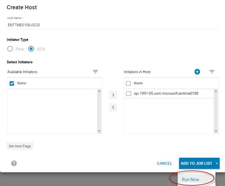
ISCSI IMPLEMENTATION FOR DELL EMC STORAGE ARRAYS RUNNING POWERMAXOS
←
→
Page content transcription
If your browser does not render page correctly, please read the page content below
Technical White Paper

 iSCSI Implementation for Dell EMC Storage
 Arrays running PowerMaxOS
 Abstract
 This document provides an in-depth overview of the PowerMaxOS iSCSI
 implementation on Dell EMC™ PowerMax and VMAX™ All Flash storage arrays.
 The technology surrounding iSCSI is discussed as well as an in-depth review of
 the PowerMaxOS iSCSI target model.

 March 2021

H14531.3
Revisions

Revisions
 Date Description
 October 2016 Initial release
 April 2018 Updated for PowerMaxOS
 September 2019 Updates for PowerMaxOS Q3 2019 release
 September 2020 Updates for PowerMaxOS Q3 2020 release
 February 2021 Minor updates

Acknowledgments
 Author: James Salvadore

This document may contain certain words that are not consistent with Dell's current language guidelines. Dell plans to update the document over
subsequent future releases to revise these words accordingly.

This document may contain language from third party content that is not under Dell's control and is not consistent with Dell's current guidelines for Dell's
own content. When such third-party content is updated by the relevant third parties, this document will be revised accordingly.

The information in this publication is provided “as is.” Dell Inc. makes no representations or warranties of any kind with respect to the information in this
publication, and specifically disclaims implied warranties of merchantability or fitness for a particular purpose.

Use, copying, and distribution of any software described in this publication requires an applicable software license.

Copyright © 2016–2021 Dell Inc. or its subsidiaries. All Rights Reserved. Dell Technologies, Dell, EMC, Dell EMC and other trademarks are trademarks
of Dell Inc. or its subsidiaries. Other trademarks may be trademarks of their respective owners. [3/2/2021] [Technical White Paper] [H14531.3]

2 iSCSI Implementation for Dell EMC Storage Arrays running PowerMaxOS | H14531.3
Table of contents

Table of contents
 Revisions.............................................................................................................................................................................2
 Acknowledgments ...............................................................................................................................................................2
 Table of contents ................................................................................................................................................................3
 Executive summary .............................................................................................................................................................6
 Audience .............................................................................................................................................................................6
 1 iSCSI overview .............................................................................................................................................................7
 1.1 Key iSCSI concepts and terminology .................................................................................................................7
 1.2 Primary benefits of iSCSI .................................................................................................................................10
 1.3 Core components of iSCSI ...............................................................................................................................10
 1.3.1 Initiators and target nodes ................................................................................................................................10
 1.3.2 Names ..............................................................................................................................................................10
 1.3.3 IP interfaces ......................................................................................................................................................11
 1.3.4 Sessions and connections ................................................................................................................................11
 1.3.5 Security and authentication ..............................................................................................................................12
 1.4 How iSCSI works ..............................................................................................................................................12
 1.4.1 The login process .............................................................................................................................................12
 1.4.2 The data transfer process .................................................................................................................................13
 1.5 How iSCSI compares with other storage transport protocols ...........................................................................14
 1.6 Deployment considerations for iSCSI ...............................................................................................................17
 1.6.1 Network considerations ....................................................................................................................................17
 1.6.2 Multipathing and availability considerations .....................................................................................................17
 1.6.3 Resource consumption considerations ............................................................................................................18
 2 PowerMaxOS iSCSI implementation overview ..........................................................................................................20
 2.1 Background.......................................................................................................................................................20
 2.2 The PowerMaxOS iSCSI implementation design objectives ............................................................................20
 2.3 PowerMaxOS iSCSI implementation core components ...................................................................................21
 2.3.1 Supported PowerMax hardware: Quad-port 25 GbE interface module ............................................................21
 2.3.2 Supported legacy PowerMax hardware: Quad-port 10 GbE interface module ................................................21
 2.3.3 PowerMaxOS iSCSI target node ......................................................................................................................22
 2.3.4 PowerMaxOS iSCSI IP interface ......................................................................................................................24
 2.3.5 CHAP authentication ........................................................................................................................................26
 2.3.6 Routing Instance ...............................................................................................................................................30
 2.4 PowerMaxOS iSCSI host connectivity limits ....................................................................................................32
 2.5 Summary ..........................................................................................................................................................32

3 iSCSI Implementation for Dell EMC Storage Arrays running PowerMaxOS | H14531.3
Table of contents

 3 PowerMax iSCSI use cases .......................................................................................................................................33
 3.1 Example 1: Basic port binding ..........................................................................................................................33
 3.2 Example 2: PowerMaxOS iSCSI multitenancy or port consolidation ...............................................................34
 4 Implementing example 1: iSCSI port binding .............................................................................................................35
 4.1 Document the current and desired configuration .............................................................................................35
 4.2 Identify all online PowerMax SE ports ..............................................................................................................36
 4.2.1 Using Unisphere for PowerMax ........................................................................................................................36
 4.2.2 Using Solutions Enabler ...................................................................................................................................37
 4.3 Create the Prod1 iSCSI configuration ..............................................................................................................38
 4.3.1 Option 1: Using the iSCSI Configuration Wizard ..............................................................................................39
 4.3.2 Option 2: Using Solutions Enabler....................................................................................................................44
 4.4 Verify connectivity between the new Prod1 IP Interfaces and the remote host iSCSI SAN IP Addresses ......50
 4.4.1 Using the ping utility in Unisphere for PowerMax .............................................................................................50
 4.4.2 Using the ping utility in Solutions Enabler ........................................................................................................52
 4.4.3 Section summary ..............................................................................................................................................53
 4.5 Create an iSCSI masking view for the Prod1 Host ...........................................................................................53
 4.5.1 Create an iSCSI host in Unisphere...................................................................................................................55
 4.5.2 Create a Masking View for the new iSCSI Host ...............................................................................................57
 4.5.3 Optional: Set up CHAP authorization on the Prod1 host initiator .....................................................................60
 4.6 Discover PowerMax iSCSI storage on the host ...............................................................................................61
 4.6.1 Discover the PowerMax Prod1 IP Interfaces using PowerShell .......................................................................62
 4.6.2 Connect to the host to the PowerMax iSCSI Targets. ......................................................................................65
 4.6.3 Troubleshooting tip: Verify the host iSCSI session status on the PowerMax...................................................68
 4.6.4 Rescan the storage on host. .............................................................................................................................70
 4.6.5 Verify the PowerMax volumes are visible to the host .......................................................................................70
 4.6.6 Optional: Online, initialize, and create a new file system on the iSCSI volumes. ............................................72
 4.6.7 Optional: Send I/O from Prod1 host to PowerMax iSCSI Storage ...................................................................78
 4.6.8 Section summary ..............................................................................................................................................79
 5 Implementing example 2: iSCSI multitenancy ............................................................................................................80
 5.1 Document the current and desired environments ............................................................................................80
 5.2 Create the Prod2 iSCSI configuration ..............................................................................................................81
 5.2.1 Create the Prod2 target and IP interface on Director 1F ..................................................................................81
 5.2.2 Create the Prod2 target and IP interface on Director 2F ..................................................................................82
 5.3 Verify connectivity between the new Prod2 IP Interfaces and the remote Prod2 host iSCSI SAN IP addresses
 82
 5.4 Create an iSCSI masking view for the Prod2 Host ...........................................................................................83

4 iSCSI Implementation for Dell EMC Storage Arrays running PowerMaxOS | H14531.3
Table of contents

 5.5 Discover and acquire PowerMax iSCSI storage on the Prod2 host .................................................................83
 6 Conclusion ..................................................................................................................................................................85
 A Configuring the iSCSI Initiator and MPIO on a Windows Server 2016 Host ..............................................................86
 A.1 Identify NICs which will be used for iSCSI on host. ..........................................................................................87
 A.2 Rename iSCSI NICs and LAN NICs for easier identification ...........................................................................87
 A.3 Enable Jumbo Frames on iSCSI NICs if supported on network ......................................................................87
 A.4 Optional: If enabled, disable DHCP on iSCSI NICs .........................................................................................88
 A.5 Use NIC hardware driver tools to add VLAN IDs to iSCSI NICs ......................................................................90
 A.6 Reexamine VLAN NICs on host .......................................................................................................................91
 A.7 Rename VLAN NIC Instances for easier identification. ....................................................................................92
 A.8 Configure IP Address and Subnet information for VLAN NICs ........................................................................92
 A.9 Verify network connectivity to POWERMAX IP Interfaces ...............................................................................94
 A.10 Verify the Microsoft iSCSI Initiator (MSiSCSI) service is started on the host ..................................................94
 A.11 Configure Windows firewall settings for the MSiSCSI service .........................................................................95
 A.12 If not already installed, install multipathing software such as PowerPath or Microsoft Multipath I/O (MPIO) on
 the Windows host .......................................................................................................................................................96
 A.13 Optional: Discover and attempt to connect to the PowerMax IP interfaces .....................................................98
 B Technical support and resources .............................................................................................................................100
 B.1 Related resources...........................................................................................................................................100

5 iSCSI Implementation for Dell EMC Storage Arrays running PowerMaxOS | H14531.3
Executive summary

Executive summary
 Dell Technologies is excited to offer iSCSI connectivity to our existing and new customers. The iSCSI storage
 protocol provides a potentially lower-cost-alternative connectivity method between hosts or virtual machines
 to Dell EMC™ PowerMaxOS-based storage arrays. At a high-level glance, the primary benefits of the iSCSI
 storage protocol are as follows:

 • Makes consolidated storage possible for a wide range of businesses
 • Enables cost-effective, scalable, secure, and highly available storage area networks (SANs)
 • Leverages existing management skills and network infrastructure
 • Delivers performance comparable to Fibre Channel
 • Provides interoperability using industry standards

 The PowerMaxOS iSCSI solution has been architected to take advantage of virtual local area networks
 (VLANs) to provide customers with greater host, port, and connection densities. The ability to use VLANs also
 provides built in multitenancy capabilities since the front-end storage ports can be virtualized and partitioned.
 This design makes the PowerMaxOS iSCSI solution an ideal connectivity choice when considering lower-cost
 storage options for converged infrastructures and all virtualized environments.

Audience
 This document is intended for Dell Technologies field personnel, including technology consultants, and for
 customer storage architects, administrators, and operators involved in managing, operating, or designing a
 storage infrastructure which contains PowerMaxOS based storage arrays.

6 iSCSI Implementation for Dell EMC Storage Arrays running PowerMaxOS | H14531.3
iSCSI overview

1 iSCSI overview
 iSCSI is a transport layer protocol that uses TCP/IP to transport SCSI packets, enabling the use of Ethernet-
 based networking infrastructure as a storage area network (SAN). Like Fibre Channel and other storage
 transport protocols, iSCSI transports block level data between an initiator on a server and a target on a
 storage device. IBM developed iSCSI as a proof of concept in 1998 and was ratified as a transport protocol by
 the Internet Engineering Task Force (IETF) in 2003. The current iSCSI standard is IETF RFC 7143 and can
 be found at https://tools.ietf.org/html/rfc7143.

1.1 Key iSCSI concepts and terminology
 This white paper will consistently use or make reference to specific concepts and terminology. The following
 table provides a detailed list of these terms and their definitions:

 Key iSCSI technologies and terminology
 Equivalent term
 Terminology
 (later instances in Definition
 (first instance in document)
 document)
 Open Systems Interconnection OSI model A seven-layer conceptual model that characterizes
 Model and standardizes the communication functions of a
 telecommunication or computer network system
 without regard to its underlying internal structure
 and technology. The primary layers are the
 application (Layer 7), Presentation (Layer 6),
 Session (Layer 5), Transport (Layer 4), Network
 (Layer 3), Datalink (Layer 2), Physical (Layer 1)
 Ethernet Ethernet A family of computer networking technologies
 operating at the OSI physical layer (Layer 1) also
 providing services to the OSI datalink layer (Layer
 2). Ethernet is comm*only used in local area
 networks (LAN) and wide area networks (WAN).
 Systems communicating over Ethernet based
 networks divide a stream of data into frames. Each
 frame contains source and destination addresses,
 and error-checking data so that damaged frames
 can be detected, discarded, and retransmitted when
 needed. Ethernet can use physical mediums of
 twisted pair and fiber optic links which can reach
 speeds of 10 Gbps (10 GbE), 25 Gbps, 40 Gbps,
 50 Gbps, and now 100 Gbps.
 Virtual Local Area Network VLAN Any broadcast domain that is partitioned and
 (VLAN) isolated in computer network at the datalink layer
 (Layer 2). VLANs work by applying tags to network
 packets and handling these tags in networking
 systems – creating the appearance and
 functionality of network traffic that is physically on a
 single network but acts as if it is split between
 separate networks.
 Transmission Control TCP/IP A suite of communication protocols used to
 Protocol/Internet Protocol interconnect devices on communication networks.
 TCP/IP specifies how data can be exchanged over
 networks. TCP defines how applications can create

7 iSCSI Implementation for Dell EMC Storage Arrays running PowerMaxOS | H14531.3
iSCSI overview

 Equivalent term
 Terminology
 (later instances in Definition
 (first instance in document)
 document)
 channels of communication across a network. It
 manages how data is assembled into smaller
 packets before it is transmitted over the network
 and how it is to be reassembled at the destination
 address. In the OSI model, TCP provides services
 to the transport layer (Layer 4) and some services
 to the session layer (Layer 5). IP specifically defines
 how to address and route each packet to ensure it
 reaches the correct destination on the network. In
 the OSI model, IP provides services to the network
 layer (Layer 3).
 Small Computer System SCSI A set of standards for physically connecting and
 Interface (SCSI) transferring data between computers and peripheral
 devices such as disk storage. The SCSI standards
 define commands, protocols, and electrical and
 optical interfaces.
 Storage Area Network SAN A specialized, high-speed network that provides
 block-level network access to storage. A SAN
 consists of two types of equipment: initiator and
 target nodes. Initiators, such as hosts, are data
 consumers. Targets, such as disk arrays or tape
 libraries, are data providers. A SAN presents
 storage devices to a host such that the storage
 appears locally attached. SAN initiators and targets
 can be interconnected using various technologies,
 topologies, and transport layer protocols.
 Internet Small Computer Serial iSCSI A transport layer protocol that uses TCP/IP to
 Interface (iSCSI) transport SCSI commands enabling Ethernet based
 networks to function as a storage area network
 (SAN). iSCSI uses TCP/IP to move block data
 between iSCSI initiators nodes and iSCSI target
 nodes
 iSCSI Initiator Node Initiator Host-based hardware (virtual or physical) or
 software which sends data to and from iSCSI target
 nodes (storage arrays). The initiator makes
 requests for the data to be read from or written to
 the storage. In case of read operations, the initiator
 sends a SCSI READ command to the peer who
 acts as a target and in return the target sends the
 requested data back to the initiator. In the case of a
 write operation, initiator sends a SCSI WRITE
 command followed by the data packets to the
 target. The initiator always initiates the transactions.
 iSCSI Target Node Target Storage arrays, tape drives, storage servers on a
 SAN. In iSCSI, targets can be associated with
 either virtual or physical entities. A storage array
 target exposes one or more SCSI LUNs to specific
 initiators. A target is the entity which processes the
 SCSI commands from the initiator. Upon receiving

8 iSCSI Implementation for Dell EMC Storage Arrays running PowerMaxOS | H14531.3
iSCSI overview

 Equivalent term
 Terminology
 (later instances in Definition
 (first instance in document)
 document)
 the command from the initiator, the target runs the
 command and then sends the requested data and
 response back to the initiator. A target cannot
 initiate any transaction.
 iSCSI IP Interface (Network IP Interface Primary gateway for access to iSCSI nodes. IP
 Portal) Interfaces contain key network configuration
 information such as: IP Address, Network ID, VLAN
 information, and TCP Port Number. An IP Interface
 can only provide access to a single iSCSI target;
 however, an iSCSI target can be accessed through
 multiple IP Interfaces.
 PowerMaxOS 5978 PowerMaxOS The PowerMaxOS 5978 release supports
 (microcode) PowerMax NVMe arrays, dedupe, and other
 software enhancements and is offered with VMAX
 All Flash arrays.
 PowerMaxOS Network Identity Network ID/NetID A PowerMaxOS construct which is used internally
 by the system to associate an array IP interface
 with an array iSCSI target. The PowerMaxOS
 Network ID is specific to a single director on the
 array and is not visible to external switches or
 hosts.
 iSCSI Qualified Names IQN Primary mechanism to identify iSCSI nodes on a
 network. These names are a human-readable
 ASCII string which can be either user or
 algorithmically generated; however, the iSCSI
 Name must be unique on a per network basis in
 order to avoid duplication.
 iSCSI Protocol Data Unit (PDU) PDU SCSI commands encapsulated and placed into
 packets by the iSCSI Protocol at the session layer
 (Layer 5).
 iSCSI Connection Connection A TCP/IP connection which ties the session
 components together. The IP addresses and TCP
 port numbers in the IP Interfaces define the end
 points of a connection.
 iSCSI Session Session Primary communication linkage between iSCSI
 initiator and target nodes. The session is the vehicle
 for the transport of the iSCSI PDUs between the
 initiators and target nodes.
 Challenge Handshake CHAP The most commonly used iSCSI authentication
 Authentication Protocol (CHAP) method. CHAP verifies identity using a hashed
 transmission of a secret key between initiator and
 target.

9 iSCSI Implementation for Dell EMC Storage Arrays running PowerMaxOS | H14531.3
iSCSI overview

1.2 Primary benefits of iSCSI
 With the proliferation of 10 GbE networking in the last few years, iSCSI has steadily gained footprint as a
 deployed storage protocol in data centers. For data centers with centralized storage, iSCSI offers customers
 many benefits. Developed by the Internet Engineering Task Force (IETF) as a response to the need for
 interoperability in networked storage, iSCSI lets businesses create TCP/IP based SANs that deliver the
 performance comparable to Fibre Channel, but at a lower cost.

 The iSCSI protocol can achieve lower costs because the protocol allows for the encapsulation of SCSI
 commands on a standard TCP/IP connection and transported over an Ethernet based network. This means
 that host standard Ethernet network interface cards (NICs) and network switches can be used to carry
 storage traffic, eliminating the need for a more expensive specialized storage network using separate
 switches and host bus adapters (HBAs). Using fewer deployed ports means fewer deployed switches which
 can result in lower infrastructure, administration, power consumption, and cooling costs. Cost reduction and
 consolidation of equipment are primary drivers behind the push to converged infrastructures; hence why
 iSCSI is a highly considered storage protocol for customers looking to go converged.

1.3 Core components of iSCSI
 iSCSI architecture is made up of a set of core components. These components are initiator and target nodes,
 iSCSI names, IP Interfaces, sessions and connections, and security.

1.3.1 Initiators and target nodes
 A storage area network (SAN) consists of two types of equipment: initiator and target nodes. Initiators, such
 as hosts, are data consumers. Targets, such as disk arrays or tape libraries, are data providers. iSCSI based
 SANs use initiators and targets in the same manner.

 • iSCSI initiator nodes are typically host based software or hardware which sends data to and from
 iSCSI target nodes (storage arrays). In data migration between storage arrays, the source array can
 act as an initiator.
 • iSCSI target nodes expose one or more SCSI LUNs to specific iSCSI initiators. On the enterprise
 storage level, iSCSI target nodes are logical entities, not tied to a specific physical port.

 iSCSI initiators must manage multiple, parallel communication links to multiple targets. Similarly, iSCSI
 targets must manage multiple, parallel communication links to multiple initiators. Several identifiers exist in the
 iSCSI protocol to make this happen, including iSCSI Name, ISID (iSCSI session identifiers), TSID (target
 session identifier), CID (iSCSI connection identifier) and iSCSI portals.

1.3.2 Names
 iSCSI nodes are identified by a unique iSCSI Name. iSCSI names are a human readable ASCII string and
 must be unique on a per NetID/Network ID basis. iSCSI names can be both user and algorithmically
 generated. iSCSI Names are formatted in two different ways:

 • Enterprise Unique Identifier (EUI): eui.0123456789ABCDEF
 • iSCSI Qualified Name (IQN): Most commonly used naming format: iqn.2001-
 05.com.mircosoft:ProdHost

10 iSCSI Implementation for Dell EMC Storage Arrays running PowerMaxOS | H14531.3
iSCSI overview

1.3.3 IP interfaces
 iSCSI Nodes are accessed through IP Interfaces (sometimes called Network Portals). iSCSI IP Interfaces
 contain key network configuration information such as:

 • IP Address
 • VLAN information
 • TCP Port Number

 An iSCSI IP Interface can only provide access to a single iSCSI node; however, an iSCSI node can be
 accessed through multiple IP Interfaces.

1.3.4 Sessions and connections
 iSCSI initiator and target nodes communicate by a linkage called an iSCSI session. The session is the
 vehicle for the transport of the iSCSI PDUs between the initiators and target nodes. Each session is started
 by the initiator logging into the iSCSI target. The session between the initiator and target is identified by an
 iSCSI session ID. Session IDs are not tied to the hardware and can persist across hardware swaps.

 Session components are tied together by a TCP/IP connection. The IP addresses and TCP port numbers in
 the IP interfaces define the end points of a connection. The iSCSI protocol allows for multiple connections
 within a single session (MC/S) as means to provide connection resiliency to a target which is presenting
 volumes to the host; however, MC/S is rarely done with enterprise iSCSI connections as most enterprise
 implementations use host-based multipath I/O software (MPIO). Using host-based MPIO, a single host
 initiator can access the same devices by presenting them through multiple targets on the storage array. This
 allows the host to see the devices through multiple paths. Each path from the initiator to the targets will have
 its own session and connection. This connectivity method is often referred to as “port binding.” The diagram
 below shows these iSCSI connectivity methods:

 iSCSI Connectivity Methods

11 iSCSI Implementation for Dell EMC Storage Arrays running PowerMaxOS | H14531.3
iSCSI overview

1.3.5 Security and authentication
 The most commonly used iSCSI authentication method is Challenge Handshake Authentication Protocol
 (CHAP). CHAP verifies identity using a hashed transmission of a secret key between initiator and target. The
 iSCSI specification RFC 7143 defines that CHAP security is the only “must-support” authentication protocol.
 All other protocols such as Kerberos are considered to “in addition to” CHAP.

 The CHAP secret key is a user-defined string up to 32 ASCII characters, or 64 binary characters (binary
 values should be prefixed with the string “0x”). Note: Windows users need to specify a secret key between 12
 and 16 ASCII characters. The users also create a credential name (CHAP username) string between 8 and
 256 ASCII characters. For more information about CHAP iSCSI considerations, please refer to RFC 7143
 section 9.2.1 which can be found at https://tools.ietf.org/html/rfc7143.

 Using CHAP, the target initiates the challenge to the initiator for the secret key. It periodically repeats the
 challenge to guard against replay attacks. CHAP can be a unidirectional /one-way protocol, in which only the
 target authenticates the initiator, but it can be implemented in two directions (bidirectional and mutual) where
 the initiator also authenticates the target to provide security for both ends. The following bullets detail these
 methods:

 • In one-way CHAP authentication, also called unidirectional, the target authenticates the initiator, but
 the initiator does not authenticate the target. With CHAP one-way authentication, the storage array
 challenges the host during the initial link negotiation process and expects to receive a valid credential
 and CHAP secret in response. When challenged, the host transmits a CHAP credential and CHAP
 secret to the storage array. The storage array looks for this credential and CHAP secret internally or
 on a network “RADIUS” server. Once a positive authentication occurs, the storage array sends an
 acceptance message to the host. However, if the storage array fails to find any record of the
 credential or secret pair, it sends a rejection message, and the link is closed.
 • In two-way CHAP authentication, also called bi-directional or mutual, an additional level of security
 enables the initiator to authenticate the target after the target authenticates the initiator. With two-way
 CHAP authentication, the host challenges and authenticates the storage array. This provides an extra
 layer of authentication and security in the iSCSI configuration as both the target and initiator act as
 authenticators and peers.

1.4 How iSCSI works
 As said earlier, the iSCSI protocol allows for the encapsulation of SCSI commands on a standard TCP/IP
 connection and transported over an Ethernet based network between a host and a storage array. These
 actions can be separated into two processes: the Login Process and the Data Transfer Process.

1.4.1 The login process
 When an iSCSI host initiator wishes to communicate with an iSCSI storage array, it begins with a login
 request. The login request contains information about “who” is sending the request and “what” storage target
 the host wishes to communicate with. If CHAP is being used, the request will contain CHAP information. The
 iSCSI storage array will authenticate the host initiator using the CHAP information. If the authentication is
 successful, the login is able to complete, and a “session” is established between the host initiator and the
 storage array target. Once the session is established, the transfer of SCSI commands and data between the
 host initiator and storage array target can begin. It is not uncommon for iSCSI sessions to remain active for
 days or months. When either the host or the storage array decides to close the session, it will either issue a
 logout command. When the session closes, the ability transfer of SCSI commands and data between the host
 and storage will also end.

12 iSCSI Implementation for Dell EMC Storage Arrays running PowerMaxOS | H14531.3
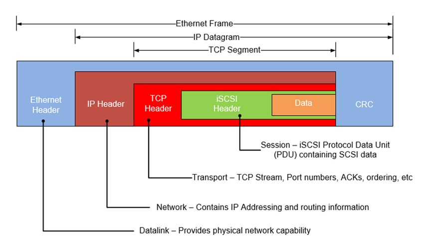
iSCSI overview

1.4.2 The data transfer process
 iSCSI transports block level data between an initiator on a host and an target on a storage array in the
 following manner:

 • The process starts with an application on a host generating a block level I/O (Layer 7)
 • The I/O is sent to the presentation Layer 6 where the I/O is translated to the SCSI command set.
 • At the session Layer 5 (where iSCSI operates), the iSCSI protocol encapsulates the SCSI commands
 and assembles them into packets called Protocol Data Units (PDUs).
 • These PDUs are then sent to the Transport Layer 4, where it is encapsulated in a TCP segment (the i
 in iSCSI).
 • It is then sent to the Network Layer 3 where it is placed into an IP datagram to form the TCP/IP
 packet.
 • The TCP/IP packet is then placed into an Ethernet frame at the Datalink Layer 2
 • The “iSCSI Ethernet” frame is then sent out onto the physical network Layer 1 to be sent to the
 storage target.

 This process is shown in the following figure:

 How iSCSI works

 When the target side receives iSCSI Ethernet frames, the target datalink layer will remove the frame
 encapsulation and pass the results up to the Network Protocol Layer. The Network layer will remove the IP
 datagram encapsulation, and the Transport layer will remove the TCP segment encapsulation, leaving a PDU
 to be passed up to the session layer (iSCSI protocol layer). The iSCSI Protocol Layer will remove the SCSI
 data from the PDU and pass it to the presentation layer for interpretation and processing.

 The figure below shows the different components in an iSCSI Ethernet frame.

13 iSCSI Implementation for Dell EMC Storage Arrays running PowerMaxOS | H14531.3
iSCSI overview

 iSCSI Ethernet frame

 Essentially there is no difference between an iSCSI Ethernet frame with a standard Ethernet frame except
 what is the payload in the TCP segment - the iSCSI PDU. There is nothing in the TCP Segment Header to
 indicate that the TCP Data Segment contains data of a specific protocol. The TCP/IP definition does not
 prevent iSCSI PDUs and other network data from being transmitted on the same network. Similarly, there is
 nothing that requires that they be mixed, so a network administrator can determine whether an isolated
 subnet for iSCSI is necessary or not. The ability to carry multiple types of data in TCP Segment header is
 what allows modern Ethernet switches to the transport of iSCSI, IP, and Fibre Channel over Ethernet (FCoE)
 on the same infrastructure.

1.5 How iSCSI compares with other storage transport protocols
 The diagram below shows the similarities and differences between iSCSI and other storage transport
 protocols. All use the standard network layer model but only iSCSI uses the standard IP protocol.

 iSCSI and other SCSI transports

 The primary storage transport protocols currently deployed in the data center today is Fibre Channel and
 Serial Attached SCSI (SAS) storage. With the proliferation of 10 GbE networks and movement to lower cost
 converged infrastructures in the data center over the last few years, iSCSI has seen a significant uptick in

14 iSCSI Implementation for Dell EMC Storage Arrays running PowerMaxOS | H14531.3
iSCSI overview deployment. FCoE has seen some uptick in deployment as well in footprint but it still lags far behind FC, SAS, and iSCSI. This is primarily because FCoE requires Ethernet to be a lossless network which requires the implementation of additional technologies such as end to end Data Center Bridging (DCB). These additional requirements add cost and complexity to the Ethernet solution, greatly reducing any cost advantages that Ethernet has over traditional Fibre Channel. The table below attempts to summarize the differences and advantages of Fibre Channel and iSCSI storage protocols. Where a protocol has an advantage is identified by the symbol. Fibre Channel and iSCSI comparison iSCSI FC Description Interconnect technology which uses Transporting protocol used to transfer SCSI Ethernet and TCP/IP to transport SCSI command sets between initiators and targets commands between initiator and targets Architecture Uses standard OSI-based network model— Uses its own five-layer model that starts at the SCSI commands sent in TCP/IP packets physical layer and progresses through to the over Ethernet upper level protocols Scalability Good. No limits to the number of devices in Excellent. 16 million SAN devices with the Score specification but subject to vendor use of switched fabric. Achieves linear limitations. Larger implementations can see performance profile as SAN scales outward performance issues due to increasing using proper edge-core-edge fabric topologies number of hops, spanning tree, and other issues. Performance Good. Not particularly well suited for large Excellent. Well suited for all IO types and Score amounts of small block IO (
iSCSI overview iSCSI FC Fibre Channel device provisioning. CHAP properly. management in larger implementations can be daunting Security Fair. Requires CHAP for authentication, Excellent – specification has built in Score VLANs or isolated physical networks for hardware level authentication and encryption, separation, IPSec for on wire encryption Switch port or WWPN zoning enables separation on Fabric Strengths Cost, good performance, ease of High performance, scalability, enterprise-class Summary virtualization, and pervasiveness of reliability and availability. Mature ecosystem. Ethernet networks in the data center and Future ready protocol - 32 Gb FC is currently cloud infrastructures. Flexible feature vs. available for FC-NVMe deployments. cost trade offs Weakness TCP overhead and workloads with large Initial investment is more expensive. Summary amounts of small block IO. CHAP, Operational costs are higher as FC requires excessive host provisioning gymnastics. separate network infrastructure. Not well suited Questions about future - will NVMe and for virtualized or cloud-based applications. NVMeoF send iSCSI the way of the Dodo? Optimal SMBs and enterprise, departmental and Enterprise with complex SANs: high number of Environments remote offices. Very well suited for IOPS and throughput converged infrastructures and application consolidation. • Non-stop corporate backbone including mainframe • Business applications running on top of smaller to mid-sized Oracle environments • High intensity OLTP/OLAP transaction processing for Oracle, IBM DB2, Large SQL • All Microsoft Business Applications such Server databases as Exchange, SharePoint, SQL Server • Quick response network for imaging and data warehousing • All Microsoft Business Applications such as Exchange, SharePoint, SQL Server The above table outlines the strengths and weaknesses of Fibre Channel vs. iSCSI when the protocols are being considered for implementation for SMB and enterprise-level SANs. Each customer has their own set of unique criteria to use in evaluating different storage interface for their environment. For most small enterprise and SMB environments looking to implement a converged, virtualized environment, the determining factors for a storage interface are upfront cost, scalability, hypervisor integration, availability, performance, and the amount of IT Expertise required to manage the environment. The above table shows that iSCSI provides a nice blend of these factors. When price to performance is compared between iSCSI and Fibre Channel, iSCSI does show itself to be compelling solution. In many data centers, particularly in the SMB space, many environments are not pushing enough IOPS to saturate even one Gbps bandwidth levels. At the time of this writing, 10 Gbps networks are becoming legacy in the data center and 25+ Gbps networks are being more commonly deployed for a network backbone. This makes iSCSI a real option for future growth and scalability as throughput demands increase. Another reason that iSCSI is considered an excellent match for converged virtualized environments, is that iSCSI fits in extremely well with a converged network vision. Isolating iSCSI NICs on a virtualized host allows 16 iSCSI Implementation for Dell EMC Storage Arrays running PowerMaxOS | H14531.3
iSCSI overview

 each NIC to have its own virtual switch and specific QoS settings. Virtual machines can be provisioned with
 iSCSI storage directly through these virtual switches, bypassing the management operating system
 completely and reducing I/O path overhead.

 Making a sound investment in the right storage protocol is for a critical step for any organization.
 Understanding the strengths and weaknesses of each of the available storage protocol technologies is
 essential. By choosing iSCSI, a customer should feel confident that they are implementing a SAN which can
 meet most of their storage workload requirements at a potentially lower cost.

1.6 Deployment considerations for iSCSI
 The following information needs to be considered and understood when deploying iSCSI into an environment.

1.6.1 Network considerations
 Network design is key to making sure iSCSI works properly and delivers the expected performance in any
 environment. The following are best practice considerations for iSCSI networks:

 • 10 GbE+ networks are essential for enterprise production level iSCSI. Anything less than 10GbE
 should be relegated to test and development.
 • iSCSI should be considered a local-area technology, not a wide-area technology, because of
 latency issues and security concerns.
 • Separate iSCSI traffic from general traffic by using either separate physical networks or layer-2
 VLANs. Best practice is to have a dedicated LAN for iSCSI traffic and not share the network with
 other network traffic. Aside from minimizing network congestion, isolating iSCSI traffic on its own
 physical network or VLAN is considered a must for security as iSCSI traffic is transmitted in an
 unencrypted format across the LAN.
 • Implement jumbo frames (by increasing the default network MTU from 1500 to 9000) in order to
 deliver additional throughput especially for small block read and write traffic. However, care must be
 taken if jumbo frames are to be implemented as they require all devices on the network to be jumbo
 frame compliant and have jumbo frames enabled. When implementing jumbo frames, set host and
 storage MTUs to 9000 and set switches to higher values such as 9216 (where possible).
 • To minimize latency, avoid routing iSCSI traffic between hosts and storage arrays. Try to keep hops
 to a minimum. Ideally host and storage should co-exist on the same subnet and be one hop away
 maximum.
 • Enable “trunk mode” on network switch ports. Many switch manufacturers will have their switch
 ports set using “access mode” as a default. Access mode allows for only one VLAN per port and is
 assuming that only the default VLAN (VLAN 0) will be used in the configuration. Once an additional
 VLAN is added to the default port configuration, the switch port needs to be in trunk mode, as trunk
 mode allows for multiple VLANs per physical port.

1.6.2 Multipathing and availability considerations
 The following are iSCSI considerations with regard to multipathing and availability:

 • Deploy port binding iSCSI configurations with multipathing software enabled on the host rather than
 use a multiple-connection-per-session (MC/S) iSCSI configuration. MC/S was created when most
 host operating systems did not have standard operating-system-level multipathing capabilities. MC/S
 is prone to command bottlenecks at higher IOPS. Also, there is inconsistent support for MC/S across
 vendors

17 iSCSI Implementation for Dell EMC Storage Arrays running PowerMaxOS | H14531.3
iSCSI overview

 • Use the "Round Robin (RR)" load balancing policy for Windows host based multipathing software
 (MPIO) and Linux systems using DM-Multipath. Round Robin uses an automatic path selection
 rotating through all available paths, enabling the distribution of load across the configured paths. This
 path policy can help improve I/O throughput. For active/passive storage arrays, only the paths to the
 active controller will be used in the Round Robin policy. For active/active storage arrays, all paths will
 be used in the Round Robin policy.
 • For Linux systems using DM-Multipath, change “path_grouping_policy” from “failover” to “multibus” in
 the multipath.conf file. This will allow the load to be balanced over all paths. If one fails, the load will
 be balanced over the remaining paths. With “failover” only a single path will be used at a time,
 negating any performance benefit. Ensure that all paths are active using “multipath –l” command. If
 paths display an “enabled” status, they are in failover mode
 • Use the “Symmetrix Optimized” algorithm for Dell EMC PowerPath software. This is the default
 policy and means that administrators do not need to change or tweak configuration parameters.
 PowerPath selects a path for each I/O according to the load balancing and failover policy for that
 logical device. The best path is chosen according to the algorithm. Due to the propriety design and
 patents of PowerPath, the exact algorithm for this policy cannot be detailed here
 • Do not use NIC teaming on NICs dedicated for iSCSI traffic. Use multipathing software such as
 native MPIO or PowerPath for path redundancy.

1.6.3 Resource consumption considerations
 When designing an iSCSI SAN, one of the primary resource considerations must be focused around the CPU
 consumption required to process the iSCSI traffic throughput on both the host initiator and storage array
 target environments. As a guideline, network traffic processing typically consumes 1 GHz of CPU cycles for
 every 1 Gbps (125 MBps) of TCP throughput. It is important to note that TCP throughput can vary greatly
 depending on workload; however, many network design teams use this rule to get a “ball park” idea of CPU
 resource sizing requirements for iSCSI traffic. The use of this rule in sizing CPU resources is best shown by
 an example.

 Consider the following: the total throughput of an iSCSI workload is estimated to be 2.5 GBps. This means
 that both the host and storage environments must be sized properly from a CPU perspective to handle the
 estimated 2.5 GBps of iSCSI traffic. Using the general guideline, processing the 2.5 GBps of iSCSI traffic will
 consume:

 2.5 (
 1000
 1
 ) (
 1
 125
 ) = 20 GHz of CPU consumption

 This means that an estimated 20 GHz of CPU resources will be consumed on both the host initiator and
 storage array target side of the environment to process the iSCSI traffic. To further examine the impact of this
 requirement, say the host initiator environment consists of a heavily virtualized dual node cluster. Each node
 has 2 x 16 core 2.5 GHz CPUs. This means that the host initiator environment has a total of:

 2 16 2.5
 2 ( ) ( ) ( ) = 160 GHz of CPU processing power

 The estimated consumption of 20 GHz CPU cycles to process the 2.5 GBps of iSCSI traffic represents 12.5%
 of the total 160 GHz processing power of the host initiator environment. In many virtualized environments, a
 two-node cluster is considered a small implementation. Many modern virtualized environments will consist of
 many nodes, with each node being dual CPU and multi-core. In these environments, 20 GHz of CPU
 consumption might seem trivial; however, in heavily virtualized environments, every CPU cycle is valuable.

18 iSCSI Implementation for Dell EMC Storage Arrays running PowerMaxOS | H14531.3
iSCSI overview

 CPU resource conservation is even more important on the storage side of the environment as CPU resources
 are often more limited than on the host initiator side.

 The impact on CPU resources by iSCSI traffic can be minimized by deploying the following into the iSCSI
 SAN environment:

 • In order to fully access the environment CPU resources, widely distribute the iSCSI traffic across
 many host nodes and storage directors ports as possible.
 • Employ NICs with a built-in TCP Offload Engine (TOE). TOE NICs offload the processing of the
 datalink, network, and transport layers from the CPU and process it on the NIC itself.
 • For heavily virtualized servers, use NICs which support Single Root - IO Virtualization (SR-IOV).
 Using SR-IOV allows the guest to bypass the hypervisor and access I/O devices (including iSCSI)
 directly. In many instances, this can significantly reduce the server CPU cycles required to process
 the iSCSI I/O.

 Note: The introduction of TOE and SR-IOV into an iSCSI environment can add complexity and cost. Careful
 analysis must be done to ensure that the additional complexity and cost is worth the increased performance.

19 iSCSI Implementation for Dell EMC Storage Arrays running PowerMaxOS | H14531.3
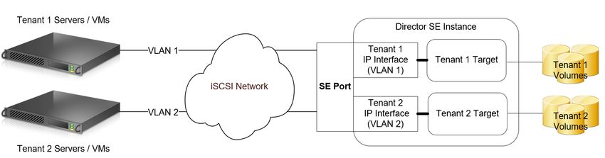
PowerMaxOS iSCSI implementation overview

2 PowerMaxOS iSCSI implementation overview
 The PowerMaxOS iSCSI target model is primarily being driven by market needs originating from the cloud or
 service-provider space, converged infrastructures, and heavily virtualized environments where slices of
 infrastructure (Compute, Network, and Storage) are assigned to different users (tenants). This model requires
 control and isolation of resources along with multitenancy capabilities not previously attainable with previous
 iSCSI implementations on previous generation of the VMAX.

2.1 Background
 The implementation of iSCSI on many storage vendors closely follows the same model as FC and FCoE
 emulations where a user is presented a physical port linked together with a target node along with a pool of
 associated devices. Using masking, users can provision LUNs to individual hosts connected to this target.
 Besides LUN masking, this model provides almost no isolation and control of software and hardware
 resources on a per tenant basis. As a result, if a tenant required partial ownership of the IO stack, which is
 normally expected in cloud service environments, then each tenant would need to access its own physical
 port. In this type of situation, scalability immediately becomes a major obstacle with this design as front-end
 port counts on storage arrays are limited. Security and lack of network isolation are other concerns with this
 model, as resources (for example, volumes and authentication information) are shared among otherwise
 independent tenants.

2.2 The PowerMaxOS iSCSI implementation design objectives
 The PowerMaxOS iSCSI target model has been designed to meet customer demands regarding control and
 isolation of resources, as well as providing a platform for greater physical port utilization and efficiencies. The
 PowerMaxOS iSCSI target model accomplishes this by the following key design principles:

 • PowerMaxOS groups director CPU resources (cores) together into logical pools. Each director
 dynamically allocates these pooled CPU resources to meet the workload demands placed upon the
 different types of front end and back-end connectivity options the director supports. These
 connectivity options and the resources they use are called “emulation instances.” PowerMaxOS
 supports iSCSI using the “SE instance.” A PowerMax director can have only one SE instance. The
 SE instance is dynamically allocated a certain number of cores which are used to process the total
 amount of TCP traffic coming in through the director’s 10/25 GbE ports.
 • Virtualization of the physical port. Users can create multiple iSCSI target nodes and IP interfaces for
 an individual port which provides:

 - Individual iSCSI targets can be assigned one or more IP interfaces, which define access network
 paths for hosts to reach the target node.
 - The implementation supports configuration of routing and VLANs for traffic isolation

 • Storage side Quality of Service (QoS) is implemented at storage group (SG) level using host I/O limits
 and PowerMaxOS service levels.

 Note: PowerMaxOS supports Ethernet PAUSE flow control; however, priority flow control (PFC) and data
 center bridging (DCB) are not supported.

20 iSCSI Implementation for Dell EMC Storage Arrays running PowerMaxOS | H14531.3
PowerMaxOS iSCSI implementation overview

2.3 PowerMaxOS iSCSI implementation core components
 The PowerMaxOS iSCSI model achieves the design objectives by using the core components:

 • A 4 x 25 GbE port or 4 x 10 GbE port interface module (required hardware), or both
 • The PowerMaxOS iSCSI Target Node
 • The PowerMaxOS iSCSI IP Interface
 • CHAP Authentication
 • IP Routing

 These new objects provide a significant amount of flexibility and allow users to define how to mix and match
 target nodes and IP interfaces over mapped physical ports. An example of using these components to create
 a multitenant environment sharing a single port is shown in the diagram below. Each of these components will
 be detailed in the sections which follow.

 Typical PowerMaxOS iSCSI multitenant architecture

2.3.1 Supported PowerMax hardware: Quad-port 25 GbE interface module
 The PowerMaxOS iSCSI target implementation uses a quad port 25 GbE hardware I/O module. This module
 has the following features:

 • High-density quad-port 25 GbE interface (four SFP+ optical transceiver connectors)
 • Support for up to four Modules/SE instance on PowerMax 2000, 3 Modules/SE instance on
 PowerMax 8000
 • Auto Negotiation between 25 GbE to 10 GbE not supported

 - Cannot use 25 GbE and 10 GbE on 25 GbE interface module. Separate 10 GbE module required
 for 10 GbE
 - Can mix separate 25 GbE and 10 GbE interface modules on same director SE instance

 • FRU and Hot Swappable
 • Dimensions: 3” w x 1.25” h x 7.875”

2.3.2 Supported legacy PowerMax hardware: Quad-port 10 GbE interface module
 The PowerMaxOS iSCSI target implementation uses a quad port 25 GbE hardware I/O module. This module
 has the following features:

 • High-density quad-port 10 GbE interface (four SFP+ optical transceiver connectors)
 • Support for up to four Modules/SE instance on PowerMax 2000, 3 Modules/SE instance on
 PowerMax 8000

21 iSCSI Implementation for Dell EMC Storage Arrays running PowerMaxOS | H14531.3
You can also read