Cisco Connected Rail Solution Implementation Guide - November 2016 - Cisco Systems, Inc. www.cisco.com
←
→
Page content transcription
If your browser does not render page correctly, please read the page content below
Cisco Connected Rail Solution
Implementation Guide
November 2016

                Cisco Systems, Inc.   www.cisco.com
Cisco and the Cisco logo are trademarks or registered trademarks of Cisco and/or its affiliates in the U.S. and other countries. To view a list of Cisco trademarks, go to this URL:
www.cisco.com/go/trademarks. Third-party trademarks mentioned are the property of their respective owners. The use of the word partner does not imply a partnership relationship
between Cisco and any other company. (1721R)

                                                                                              2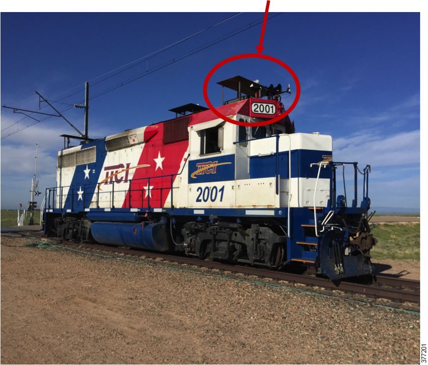
Contents
Connected Rail Solution Implementation Guide. . . . . . . . . . . . . . . . . . . . . . . . . . . . . . 1
Audience . . . . . . . . . . . . . . . . . . . . . . . . . . . . . . . . . . . . . . . . . . . . . . . . . . . . . . . . . . . . . 1
Organization . . . . . . . . . . . . . . . . . . . . . . . . . . . . . . . . . . . . . . . . . . . . . . . . . . . . . . . . 1
Solution Overview. . . . . . . . . . . . . . . . . . . . . . . . . . . . . . . . . . . . . . . . . . . . . . . . . . . . . . . 2
Network Topology . . . . . . . . . . . . . . . . . . . . . . . . . . . . . . . . . . . . . . . . . . . . . . . . . . . . . . 2
Solution Components . . . . . . . . . . . . . . . . . . . . . . . . . . . . . . . . . . . . . . . . . . . . . . . . . . . . 4
Connected Trackside Implementation . . . . . . . . . . . . . . . . . . . . . . . . . . . . . . . . . . . . . . . . 5
Wireless Offboard . . . . . . . . . . . . . . . . . . . . . . . . . . . . . . . . . . . . . . . . . . . . . . . . . . . . 6
Long Term Evolution . . . . . . . . . . . . . . . . . . . . . . . . . . . . . . . . . . . . . . . . . . . . . . . 6
Fluidmesh . . . . . . . . . . . . . . . . . . . . . . . . . . . . . . . . . . . . . . . . . . . . . . . . . . . . . . . 6
MPLS Transport Network . . . . . . . . . . . . . . . . . . . . . . . . . . . . . . . . . . . . . . . . . . . . . . 8
MPLS Transport Gateway Configuration. . . . . . . . . . . . . . . . . . . . . . . . . . . . . . . . . 9
Pre-Aggregation Node Configuration. . . . . . . . . . . . . . . . . . . . . . . . . . . . . . . . . . 10
Dual Homed Hub-and-Spoke Ethernet Access . . . . . . . . . . . . . . . . . . . . . . . . . . 12
Per VLAN Active/Active MC-LAG (pseudo MC-LAG). . . . . . . . . . . . . . . . . . . . . . 15
L3VPN Service Implementation . . . . . . . . . . . . . . . . . . . . . . . . . . . . . . . . . . . . . . 20
Connected Train Implementation . . . . . . . . . . . . . . . . . . . . . . . . . . . . . . . . . . . . . . . . . . 28
REP Ring . . . . . . . . . . . . . . . . . . . . . . . . . . . . . . . . . . . . . . . . . . . . . . . . . . . . . . . . . . 28
Gateway Mobility. . . . . . . . . . . . . . . . . . . . . . . . . . . . . . . . . . . . . . . . . . . . . . . . . . . . 30
Lilee Systems . . . . . . . . . . . . . . . . . . . . . . . . . . . . . . . . . . . . . . . . . . . . . . . . . . . 30
Klas Telecom TRX-R6 . . . . . . . . . . . . . . . . . . . . . . . . . . . . . . . . . . . . . . . . . . . . . 33
Wireless Offboard . . . . . . . . . . . . . . . . . . . . . . . . . . . . . . . . . . . . . . . . . . . . . . . . . . . 49
LTE . . . . . . . . . . . . . . . . . . . . . . . . . . . . . . . . . . . . . . . . . . . . . . . . . . . . . . . . . . . 49
Fluidmesh . . . . . . . . . . . . . . . . . . . . . . . . . . . . . . . . . . . . . . . . . . . . . . . . . . . . . . 53
Overlay Services Implementation . . . . . . . . . . . . . . . . . . . . . . . . . . . . . . . . . . . . . . . . . . 57
Video Surveillance. . . . . . . . . . . . . . . . . . . . . . . . . . . . . . . . . . . . . . . . . . . . . . . . . . . 57
Installation and Initial Setup . . . . . . . . . . . . . . . . . . . . . . . . . . . . . . . . . . . . . . . . . 57
Camera Template - Basic 24x7 Recording . . . . . . . . . . . . . . . . . . . . . . . . . . . . . 58
Camera Template - Scheduled Recording . . . . . . . . . . . . . . . . . . . . . . . . . . . . . . 59
Event-Based Recording Options . . . . . . . . . . . . . . . . . . . . . . . . . . . . . . . . . . . . . 61
Connected Edge Storage . . . . . . . . . . . . . . . . . . . . . . . . . . . . . . . . . . . . . . . . . . 62
Long Term Storage . . . . . . . . . . . . . . . . . . . . . . . . . . . . . . . . . . . . . . . . . . . . . . . 63
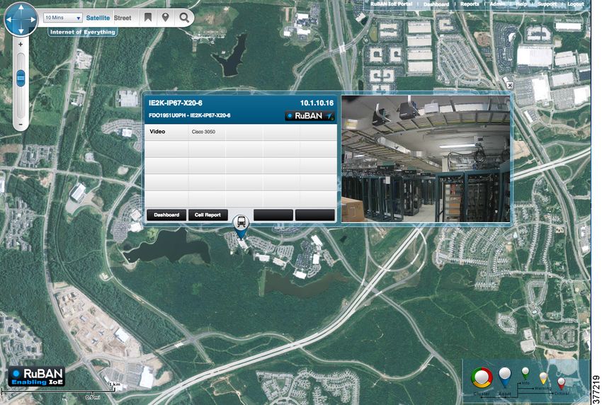
Integration with Davra RuBAN . . . . . . . . . . . . . . . . . . . . . . . . . . . . . . . . . . . . . . . 64
Wi-Fi Access Implementation . . . . . . . . . . . . . . . . . . . . . . . . . . . . . . . . . . . . . . . . . . . . . 68
Cisco Systems, Inc. www.cisco.com
1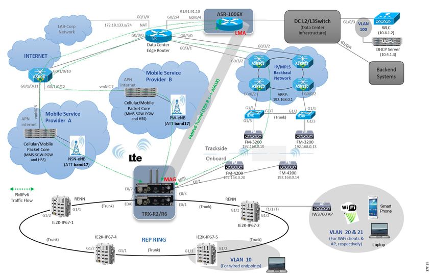
Web Passthrough . . . . . . . . . . . . . . . . . . . . . . . . . . . . . . . . . . . . . . . . . . . . . . . . . .             72
Performance, Scale, and QoS . . . . . . . . . . . . . . . . . . . . . . . . . . . . . . . . . . . . . . . . . . . .                 74
    QoS. . . . . . . . . . . . . . . . . . . . . . . . . . . . . . . . . . . . . . . . . . . . . . . . . . . . . . . . . . . . .    74
    Klas Throughput Performance . . . . . . . . . . . . . . . . . . . . . . . . . . . . . . . . . . . . . . . . .                   77
    Scale . . . . . . . . . . . . . . . . . . . . . . . . . . . . . . . . . . . . . . . . . . . . . . . . . . . . . . . . . . . .   77
Field Trial Results . . . . . . . . . . . . . . . . . . . . . . . . . . . . . . . . . . . . . . . . . . . . . . . . . . . . .       77
Glossary . . . . . . . . . . . . . . . . . . . . . . . . . . . . . . . . . . . . . . . . . . . . . . . . . . . . . . . . . . . .    85

                                                                    2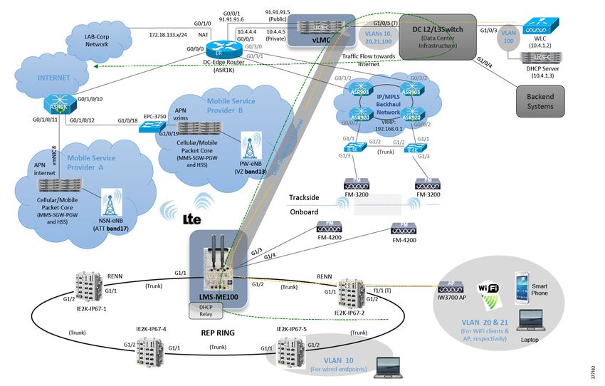
Connected Rail Solution Implementation
Guide
    This document is the Cisco Connected Rail Solution Implementation Guide, which provides details about the test
    topology, relevant feature configuration, and deployment of this solution. It is meant to be representative of a deployed
    solution and not all-inclusive for every feature presented. It will assist in deploying solutions faster by showing an
    end-to-end configuration along with relevant explanations.

    Previous releases of the Connected Transportation System focused on Positive Train Control, Connected Roadways, and
    Connected Mass Transit.

Audience
    The audiences for this document are Cisco account teams, Cisco Advanced Services teams, and systems integrators
    working with rail authorities. It is also intended for use by the rail authorities to understand the features and capabilities
    enabled by the Cisco Connected Rail Solution design.

Organization
    This guide includes the following sections:

     Solution Overview, page 2                  Provides an overview of the Connected Rail Solution services.
     Network Topology, page 2                   Description of network topology for the two ways that exist to implement the
                                                solution.
     Solution Components, page 4                Lists major solution components.
     Connected Trackside Implementation,        Describes the configuration of the trackside network infrastructure.
     page 5
     Connected Train Implementation,            Describes the configuration of the REP ring, Gateway Mobility, and Wireless
     page 28                                    Offboard.
     Overlay Services Implementation,           Describes the configuration of video surveillance that is used to provide live
     page 57                                    and recorded video to security personnel.
     Wi-Fi Access Implementation,               Describes the Wi-Fi configuration that is used to enable connectivity for the
     page 68                                    passengers on the train, law enforcement personnel, and the rail employees.
     Performance, Scale, and QoS,               Describes QoS, Klas Throughput Performance, and Scale for this solution.
     page 74
     Field Trial Results, page 77               Describes real world wireless field trial results.
     Glossary, page 85                          List of acronyms and initialisms used in this document.

                                          Cisco Systems, Inc.       www.cisco.com

                                                               1
Connected Rail Solution Implementation Guide
Solution Overview
Solution Overview
This section will provide an overview of the Connected Rail Solution services, including the Connected Trackside
implementation, Connected Train, overlay services such as video surveillance and infotainment, and onboard Wi-Fi
service.
The Connected Trackside implementation includes the network topology supporting the data center services,
Multiprotocol Label Switching (MPLS) backhaul, Long Term Evolution (LTE), and trackside wireless radios. When the
train is in motion, it must maintain a constant seamless connection to the data center services by means of a mobility
anchor. This mobility anchor maintains tunnels over each connection to the train and can load share traffic or failover
links if one of the links fail.
The Connected Train implementation includes the network topology supporting the intra-train communications
among all the passengers, employees, law enforcement personnel, and onboard systems. It also helps enable the
video surveillance, voice communications, and data traffic offloading to the trackside over the wireless network.
The overlay services depend on the Connected Train implementation and include video surveillance, infotainment,
and network management. Video surveillance is provided by the Cisco Video Surveillance Management system,
which includes the Video Surveillance Operations Manager (VSOM), and Long Term Storage (LTS) server in the data
center, a Video Surveillance Media Server (VSMS) locally onboard the train, and a number of rail-certified IP cameras
on the train. The passengers can access local information or entertainment from the onboard video servers and the
employees or law enforcement officers can see the video surveillance feeds in real-time. The Davra RuBAN network
management system is used for incident monitoring triggered by a number of soft or hard triggers.
The onboard Wi-Fi service provides connectivity to all train passengers with separate Service Set Identifiers (SSIDs)
for passengers, employees, and law enforcement personnel. This traffic is tunneled back to the data center and
relies on the seamless roaming provided by the Connected Train implementation to provide a consistent user
experience.
QoS, performance and scale, and results from a live field trial to test wireless roaming at high speed are also covered in
later chapters.
The Cisco Connected Rail Design Guide is a companion document to this Implementation Guide. The Design Guide,
which includes design options for all the services and this guide details the validation of all the services but not
necessarily all the available options, can be found at the following URL:
https://docs.cisco.com/share/proxy/alfresco/url?docnum=EDCS-11479438
Network Topology
In this solution, two distinct ways exist to implement the proposed solutions. In both, the passengers and other riders on
the train need access to network resources from the Internet, the provider's data center, or within the train. Both
implementations use a gateway on the train that forms tunnels with a mobility anchor in the provider's network.
The Lilee solution uses Layer 2 tunneling to bridge the train Local Area Network (LAN) to a LAN behind the mobility
anchor. In this respect, the Lilee solution is similar to a Layer 2 Virtual Private Network (L2VPN).
The Klas Telecom solution relies on Cisco IOS and specifically PMIPv6 to provide the virtual connection from the train
gateway to the mobility anchor in the data center. The networks on the train are advertised to the mobility anchor as
Layer 3 mobile routes. These mobile routes are only present on the mobility anchor and not the intermediate
transport nodes, so the Klas Telecom solution is similar to a Layer 3 Virtual Private Network (L3VPN).
The onboard network behind the mobility gateway is common to both solutions. Each car has a number of switches that
are connected to the cars in front and behind to form a ring. Cisco Resilient Ethernet Protocol (REP) is configured on the
switches to prevent loops and reduce the convergence time in the event of a link or node failure. The proposed switches
are the IP67-rated Cisco IE 2000 or the Klas Telecom S10/S26, which is based on the Cisco Express Security
Specialization (ESS) 2020. In each carriage, one or more wireless access points (the hardened Cisco IW3702) exist to
provide wireless access to the passengers. These access points communicate with a Wireless LAN Controller (WLC)
2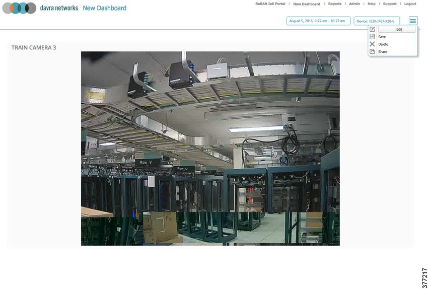
Connected Rail Solution Implementation Guide

Network Topology

      installed in the data center. For video surveillance, each carriage also has a number of IP cameras, which communicate
      with an onboard hardened server running the Cisco VSMS. An onboard infotainment system is also supported on the
      train to provide other services to the passengers.

      The Klas gateway solution is based on a virtualized Cisco Embedded Services Router (ESR) with Proxy Mobile IPv6
      (PMIPv6) performing the mobility management running on the Klas TRX-R6 or TRX-R2. The Klas gateway on the train
      performs the role of Mobile Access Gateway (MAG) while a Cisco Aggregation Services Router (ASR) 100X in the data
      center performs the role of Local Mobility Anchor (LMA).

      An example of an end-to-end system based on the IOS/Klas Telecom gateway is shown in Figure 1.

      Figure 1     Topology Diagram for Solution Based on IOS/Klas Gateway

      In the system based on the Lilee gateway, the MIG2450-ME-100 (sometimes referred to as ME-100) mobile gateway on
      the train builds an Layer 2 tunnel over the infrastructure to the virtual Lilee Mobility Controller (vLMC) in the data center.
      After the tunnel is formed, the vLMC will bridge all the train traffic to an access VLAN or VLAN trunk.

      An example of an end-to-end system based on the Lilee gateway is shown in Figure 2.

                                                                 3
Connected Rail Solution Implementation Guide
Solution Components
Figure 2 Topology Diagram for System Based on Lilee Gateway
Solution Components
The Connected Rail Solution includes onboard, trackside, backhaul, and data center equipment.
The train equipment includes:
Klas Telecom TRX-R2/R6 (for the Cisco IOS-based solution)
Lilee Systems ME-100 (for the Lilee Systems-based solution)
Cisco IE2000-IP67 switch
Klas Telecom TRX-S10/S26 switch
Cisco IW3702 access point
Cisco IPC-3050/IPC-7070 IP camera
Fluidmesh FM4200 radio
Cisco VSMS on a rail certified server
The trackside equipment includes:
Cisco IE 4000 switch
Cisco ASR 920/903 router
4
Connected Rail Solution Implementation Guide
Connected Trackside Implementation
Fluidmesh FM3200 radio
To support the train and trackside deployment, the data center includes:
Cisco ASR 100X router
Cisco WLC
Cisco Unified Computing System (UCS) to support applications including:
— DHCP
— RuBAN Network Management
— Cisco VSOM
Hardware model numbers and software releases that were validated are listed in Table 1..
Table 1 Hardware Models and Software Releases
Hardware Software Release Role
Cisco IW3702-4E-x-K9 Release 8.2 Onboard wireless access point
Cisco CIVS-IPC-3050 / CIVS-IPC-7070 Release 2.8 IP camera
Cisco AIR-CT5508 Release 8.2 Wireless LAN controller
Klas Telecom TRX-R2/R6 ESR5921 IOS 15.6(2)T Onboard mobile gateway
Klas Telecom TRX-S10/S26 ESS2020 IOS 15.2(4)EA1 Onboard access switch
Lilee Systems LMS-2450-ME-100 LileeOS Release 3.1 Onboard mobile gateway
Lilee Virtual LMC LileeOS Release 3.1 Mobility anchor for Lilee
Fluidmesh FM4200 Release 8.1 Offboarding radio for train to track
communication
Fluidmesh FM3200 Release 8.1 Trackside wireless radio
Cisco IE-2000 IP67 IOS 15.2(4)EA1 Onboard access switch
Cisco ASR 1000 IOS-XE 3.16.1aS Mobility anchor for train gateways
Cisco UCS Server platform for hosting Lilee vLMC,
Davra RuBAN
Cisco IE 4000 IOS 15.2(4)EA1 Trackside access switch
Cisco ASR 920 XE 3.18.0S Trackside pre-aggregation node
Cisco ASR 903 XE 3.18.0S Trackside pre-aggregation / aggregation
node
Connected Trackside Implementation
This section includes the following major topics:
Wireless Offboard, page 6
MPLS Transport Network, page 8
Per VLAN Active/Active MC-LAG (pseudo MC-LAG), page 15
L3VPN Service Implementation, page 20
5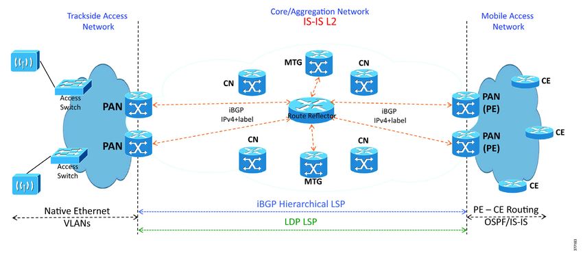
Connected Rail Solution Implementation Guide

Connected Trackside Implementation

Wireless Offboard
      The trackside wireless infrastructure includes everything needed to support a public or private LTE network and the
      Fluidmesh radio network. A public mobile operator using a public or private Access Point Name (APN) provides the LTE
      network in this solution. The Fluidmesh radios operate in the 4.9 - 5.9 GHz space using a proprietary implementation to
      facilitate nearly seamless roaming between trackside base stations.

Long Term Evolution
      The LTE implementation in this solution relies on a public mobile operator. A detailed description of this setup is out of
      scope for this document. Because the train operator may use multiple LTE connections, the mobility anchor address must
      be reachable from each public LTE network. In both the Klas Telecom and Lilee Systems gateway implementations, the
      mobility anchor must have a single publicly reachable IP address to terminate the tunnels over the LTE connections.

Fluidmesh
      The trackside radios are responsible for bridging the wireless traffic from the train to the trackside wired connections.
      Within a group of trackside radios, one is elected or configured as a mesh end and the rest are mesh points. The mesh
      point radios will forward the data from the connected train radios to the mesh end radio. The mesh end radio is similar
      to a root radio and acts as the local anchor point for all the traffic from the trackside radios. It is configured with a default
      gateway and performs all the routing for the trackside radio data.

      The trackside radios are connected to the trackside switch network on a VLAN shared with the other trackside radios,
      which is connected to the MPLS backhaul via a service instance (Bridge Domain Interface or BDI) on the provider edge
      router. The trackside switched network is configured in a REP ring connected to a pair of provider edge routers for
      redundancy. The provider edge routers run Virtual Router Redundancy Protocol (VRRP) between the BDIs to provide a
      single virtual gateway address for the trackside radios. The BDIs are then placed in a L3VPN Virtual Routing and
      Forwarding (VRF) for transit across the MPLS backhaul to the data center network.

      The radios are configured through a web interface with the default IP set to 192.168.0.10/24. Figure 3 shows an example
      of a mesh end radio configuration.

      Figure 3     Trackside Radio General Mode

      The radio is configured as a trackside radio on the FLUIDITY page. The unit role in this case is Infrastructure.

                                                                      6
Connected Rail Solution Implementation Guide
Connected Trackside Implementation
Figure 4 Trackside Radio FLUIDITY Configuration
After performing this configuration, new links will be available, FLUIDITY Quadro and FMQuadro.
Figure 5 Trackside Radio FLUIDITY Quadro
In this view, the trackside radios are displayed with the associated train radio seen as a halo around it. The real time signal
strength of the train radio is also shown.
During a roam, the train radio halo will move to the strongest trackside radio in range. In Figure 6, the signal strength is
shown after a roaming event.
7Connected Rail Solution Implementation Guide
Connected Trackside Implementation
Figure 6 Trackside Radio FLUIDITY Quadro - Roam
MPLS Transport Network
The core and aggregation networks are integrated with a flat Interior Gateway Protocol (IGP) and Label Distribution
Protocol (LDP) control plane from the core to the Pre-Aggregation Nodes (PANs) in the aggregation domain. An example
MPLS transport network is shown in Figure 7.
Figure 7 Flat IGP/LDP Network with Ethernet Access
All nodes--MPLS Transport Gateway (MTG), Core, Aggregation Node (AGN), and PAN--n the combined
core-aggregation domain make up the IS-IS Level-2 domain or Open Shortest Path First (OSPF) backbone area.
In this model, the access network could be one of the following options:
Routers configured as Customer Edge (CE) devices in point-to-point or ring topologies over fiber Ethernet running
native IP transport, supporting L3VPN services. In this case, the CEs pair with PANs configured as L3VPN Provider
Edges (PEs), enabling layer 3 backhaul. Other options are any Time Division Multiplexing (TDM) circuits connected
directly to the PANs, which provide Circuit Emulation services via pseudowire-based circuit emulation to the MTG.
8Connected Rail Solution Implementation Guide
Connected Trackside Implementation
Ethernet Access Nodes in point-to-point and REP-enabled ring topologies over fiber access running native Ethernet.
In this case, the PANs provide service edge functionality for the services from the access nodes and connect the
services to the proper L2VPN or L3VPN service backhaul mechanism. The MPLS services are always enabled by the
PANs in the aggregation network.
MPLS Transport Gateway Configuration
This section shows the IGP/LDP configuration required on the MTG to build the Label Switched Paths (LSPs) to the PANs.
Figure 8 MPLS Transport Gateway
Interface Configuration
interface Loopback0
description Global Loopback
ipv4 address 100.111.15.1 255.255.255.255
!
!***Core-facing Interface***
interface TenGigE0/0/0/0
description To CN-K0201 (CORE) Ten0/0/0/0
cdp
service-policy output PMAP-NNI-E
ipv4 address 10.2.1.9 255.255.255.254
carrier-delay up 2000 down 0
load-interval 30
transceiver permit pid all
!
!***Core-facing Interface***
interface TenGigE0/0/0/1
description To CN-K0401 (CORE) Ten0/0/0/1
cdp
service-policy output PMAP-NNI-E
ipv4 address 10.4.1.5 255.255.255.254
carrier-delay up 2000 down 0
load-interval 30
transceiver permit pid all
!
IGP Configuration
router isis core-agg
set-overload-bit on-startup 250
net 49.0100.1001.1101.5001.00
nsf cisco
log adjacency changes
lsp-gen-interval maximum-wait 5000 initial-wait 50 secondary-wait 200
lsp-refresh-interval 65000
max-lsp-lifetime 65535
address-family ipv4 unicast
metric-style wide
9Connected Rail Solution Implementation Guide
Connected Trackside Implementation
ispf
spf-interval maximum-wait 5000 initial-wait 50 secondary-wait 200
!
interface Loopback0
passive
point-to-point
address-family ipv4 unicast
!
!
interface TenGigE0/0/0/0
circuit-type level-2-only
bfd minimum-interval 15
bfd multiplier 3
bfd fast-detect ipv4
point-to-point
address-family ipv4 unicast
fast-reroute per-prefix level 2
metric 10
mpls ldp sync
!
!
interface TenGigE0/0/0/1
circuit-type level-2-only
bfd minimum-interval 15
bfd multiplier 3
bfd fast-detect ipv4
point-to-point
address-family ipv4 unicast
fast-reroute per-prefix level 2
metric 10
mpls ldp sync
!
!
!
mpls ldp
router-id 100.111.15.1
discovery targeted-hello accept
nsr
graceful-restart
session protection
igp sync delay 10
log
neighbor
graceful-restart
session-protection
nsr
!
interface TenGigE0/0/0/0
!
interface TenGigE0/0/0/1
!
!
Pre-Aggregation Node Configuration
This section shows the IGP/LDP configuration required to build the intra-domain LSPs. Minimal BGP configuration is
shown as the basis for building the transport MPLS VPN.
10Connected Rail Solution Implementation Guide
Connected Trackside Implementation
Figure 9 Pre-Aggregation Node (PAN)
Interface Configuration
interface Loopback0
ip address 100.111.14.3 255.255.255.255
!
!***Redundant PAN interface***
interface TenGigabitEthernet0/0/0
description To PAN-K1404 Ten0/0/0
ip address 10.14.3.0 255.255.255.254
ip router isis core
load-interval 30
carrier-delay msec 0
mpls ip
mpls ldp igp sync delay 10
bfd interval 50 min_rx 50 multiplier 3
no bfd echo
cdp enable
isis network point-to-point
isis metric 10
isis csnp-interval 10
service-policy output PMAP-NNI-E
hold-queue 1500 in
hold-queue 2000 out
!
!***Uplink interface***
interface TenGigabitEthernet0/1/0
description To AGN-K1102 Ten0/0/0/1
ip address 10.11.2.1 255.255.255.254
ip router isis core
load-interval 30
carrier-delay msec 0
mpls ip
mpls ldp igp sync delay 10
bfd interval 50 min_rx 50 multiplier 3
no bfd echo
cdp enable
isis circuit-type level-2-only
isis network point-to-point
isis metric 10
service-policy output PMAP-NNI-E
hold-queue 1500 in
hold-queue 2000 out
!
!***Interface toward native IP CE ring in MPLS VPN VRFS***
!***Shown here for reference. Not part of Unified MPLS config.***
interface GigabitEthernet0/4/2
description To CSG-901-K1314
vrf forwarding RFS
ip address 10.13.14.1 255.255.255.254
11Connected Rail Solution Implementation Guide
Connected Trackside Implementation
ip ospf network point-to-point
load-interval 30
negotiation auto
bfd interval 50 min_rx 50 multiplier 3
no bfd echo
hold-queue 350 in
hold-queue 2000 out
!
IGP/LDP Configuration
router isis core-agg
net 49.0100.1001.1101.4003.00
!***PAN is a IS-IS Level-1-2 node***
ispf level-1-2
metric-style wide
fast-flood
set-overload-bit on-startup 180
max-lsp-lifetime 65535
lsp-refresh-interval 65000
spf-interval 5 50 200
prc-interval 5 50 200
lsp-gen-interval 5 5 200
no hello padding
log-adjacency-changes
nsf cisco
passive-interface Loopback0
bfd all-interfaces
mpls ldp sync
!
mpls label protocol ldp
mpls ldp graceful-restart
mpls ldp discovery targeted-hello accept
mpls ldp router-id Loopback0 force
Dual Homed Hub-and-Spoke Ethernet Access
Dual homed topologies for hub-and-spoke access have been implemented in the following mode:
Per Node Active/Standby Multi-Chassis Link Aggregation Group (MC-LAG)
Per VLAN Active/Active MC-LAG (pseudo Multichassis Link Aggregation Control Protocol or mLACP)
Figure 10 Per Node Active/Standby MC-LAG
Per Node Active/Standby MC-LAG
The Ethernet access node is Dual Homed to the AGN nodes using a bundle interface. The AGN node establishes an
inter-chassis bundle and correlates the states of the bundle member ports using Inter-Control Center Communications
Protocol (ICCP).
12Connected Rail Solution Implementation Guide
Connected Trackside Implementation
At steady state, links connected to AGN1 are selected as active, while links to AGN2 are kept in standby state ready to
take over in case of a failure.
The following configuration shows the implementation of the AGN nodes, AGN-K1101 and AGN-K1102, and the Ethernet
Access Node.
Aggregation Node Configuration
AGN1: Active Point-of-Attachment (PoA) AGN-K1101: ASR9000
NNI Interfaces
For reference throughout this document, the following is a list of settings used for MC-LAG configuration.
The access-facing virtual bundle interface is configured as follows:
Suppress-flaps timer set to 300 ms. This prevents the bundle interface from flapping during a LACP failover.
Associated with ICCP redundancy group 300.
Lowest possible port-priority (to ensure node serves as active PoA initially).
Media Access Control (MAC) address for bundle interface. This needs to match the MAC address configured on the
other PoA's bundle interface.
Wait-while timer set to 100 ms to minimize LACP failover time.
Maximum links allowed in the bundle limited to 1. This configuration ensures that the access node will never enable
both links to the PoAs simultaneously if ICCP signaling between the PoAs fails.
!*** Interface configuration towards the OLT ***
interface TenGigE0/2/0/1
bundle id 102 mode active
!
interface Bundle-Ether102
mlacp iccp-group 102
mlacp switchover type revertive
mlacp switchover recovery-delay 300
mlacp port-priority 10
mac-address 0.1101.1102
!
ICCP and Multichassis LACP
For reference throughout this document, the following is a list of settings used for ICCP configuration. The ICCP
redundancy group is configured as follows:
Group ID.
mLACP node ID (unique per node).
mLACP system MAC address and priority (same for all nodes). These two values are concatenated to form the
system ID for the virtual LACP bundle.
ICCP peer address. Since ICCP works by establishing an LDP session between the PoAs, the peer's LDP router ID
should be configured.
Backbone interfaces. If all interfaces listed go down, core isolation is assumed and a switchover to the standby PoA
is triggered.
!*** ICCP configuration ***
redundancy
13Connected Rail Solution Implementation Guide
Connected Trackside Implementation
iccp
group 102
mlacp node 1
mlacp system mac 0000.1101.1111
mlacp system priority 20
member
neighbor 100.111.11.2
!
backbone
interface TenGigE0/0/0/0
interface TenGigE0/0/0/2
!
!
!
!
AGN2: Active Point-of-Attachment (PoA) AGN-A9K-K1102: ASR9000
NNI Interfaces
interface Bundle-Ether300
!*** Interface configuration towards the OLT ***
interface TenGigE0/1/1/1
bundle id 102 mode active
!
interface Bundle-Ether102
mlacp iccp-group 102
mlacp switchover type revertive
mlacp switchover recovery-delay 300
mlacp port-priority 20
mac-address 0.1101.1102
!
ICCP and Multichassis LACP
The ICCP redundancy group is configured as follows:
Group ID.
mLACP node ID (unique per node).
mLACP system MAC address and priority (same for all nodes). These two values are concatenated to form the
system ID for the virtual LACP bundle.
ICCP peer address. Since ICCP works by establishing an LDP session between the PoAs, the peer's LDP router ID
should be configured.
Backbone interfaces. If all interfaces listed go down, core isolation is assumed and a switchover to the standby PoA
is triggered.
!*** ICCP Configuration ***
redundancy
iccp
group 102
mlacp node 2
mlacp system mac 0000.1101.1111
mlacp system priority 20
member
neighbor 100.111.11.1
!
backbone
interface TenGigE0/0/0/0
interface TenGigE0/0/0/2
!
!
14Connected Rail Solution Implementation Guide
Connected Trackside Implementation
!
!
Ethernet Access Node Configuration
The following configuration is taken from a Cisco router running IOS. Configurations for Ethernet switches and other
access nodes can be easily derived from the following configuration.
NNI Interfaces
!*** Interface configuraton towards the AGN nodes ***
interface GigabitEthernet0/8
description por to 1101 gi 0/0/1/16
no ip address
load-interval 30
negotiation auto
channel-protocol lacp
channel-group 6 mode active
!
interface GigabitEthernet0/6
description por to 1102 gi 0/0/1/17
no ip address
load-interval 30
negotiation auto
channel-protocol lacp
channel-group 6 mode active
!
!*** Port-Channel configuration towards the AGN nodes ***
interface Port-channel6
no ip address
load-interval 30
no negotiation auto
ethernet dot1ad nni
!
!
Per VLAN Active/Active MC-LAG (pseudo MC-LAG)
The Ethernet access node connects to each AGN via standalone Ethernet links or Bundle interfaces that are part of a
common bridge domain(s). All the links terminate in a common multi-chassis bundle interface at the AGN and are placed
in active or hot-standby state based on node and VLAN via ICCP-SM negotiation.
In steady state conditions, each AGN node forwards traffic only for the VLANs is responsible for, but takes over
forwarding responsibility for all VLANs in case of peer node or link failure.
The following configuration example shows the implementation of active/active per VLAN MC-LAG for VLANs 100 and
101, on the AGN nodes, AGN-K1101 and AGN-K1102, and the Access Node, ME-K0904.
15Connected Rail Solution Implementation Guide
Connected Trackside Implementation
Figure 11 Per VLAN Active/Active MC-LAG
Aggregation Nodes Configuration
AGN1: Active Point-of-Attachment (PoA) AGN-A9K-K1101: ASR9000
NNI Interfaces
interface Bundle-Ether1
!
interface Bundle-Ether1.100 l2transport
encapsulation dot1q 100
!
interface Bundle-Ether1.101 l2transport
encapsulation dot1q 101
!
interface GigabitEthernet0/0/1/1
bundle id 1 mode on
ICCP and ICCP-SM and mLACP
For reference throughout this document, here is a list of settings used for ICCP-SM configuration. The ICCP-SM
redundancy group is configured as follows:
Group ID.
Multi-homing node ID (1 or 2 unique per node).
ICCP peer address. Since ICCP works by establishing an LDP session between the PoAs, the peer's LDP router ID
should be configured.
Backbone interfaces. If all interfaces listed go down, core isolation is assumed and a switchover to the standby PoA
is triggered.
redundancy
iccp
group 1
member
neighbor 100.111.11.2
!
backbone
interface TenGigE0/0/0/0
interface TenGigE0/0/0/2
!
!
!
!
l2vpn
redundancy
iccp group 1
16Connected Rail Solution Implementation Guide
Connected Trackside Implementation
multi-homing node-id 1
interface Bundle-Ether1
primary vlan 100
secondary vlan 101
recovery delay 60
!
!
!
Standby Point-of-Attachment (PoA) AGN-A9K-K1102: ASR9000
NNI Interfaces
interface GigabitEthernet0/3/1/12
bundle id 1 mode on
!
interface Bundle-Ether1
!
interface Bundle-Ether1.100 l2transport
encapsulation dot1q 100
!
interface Bundle-Ether1.101 l2transport
encapsulation dot1q 101
!
ICCP and mLACP
The ICCP redundancy group is configured as follows:
redundancy
iccp
group 1
member
neighbor 100.111.11.1
!
backbone
interface TenGigE0/0/0/0
interface TenGigE0/0/0/2
!
!
!
!*** ICCP-SM configuration ***
l2vpn
redundancy
iccp group 1
multi-homing node-id 2
interface Bundle-Ether1
primary vlan 101
secondary vlan 100
!
!
!
Ethernet Access Node
In this example, the Ethernet access node is a Cisco Ethernet switch running IOS. Configurations for other access node
devices can be easily derived from this configuration example, given that it shows a simple Ethernet trunk configuration
for each interface.
NNI Interfaces
interface GigabitEthernet0/13
port-type nni
switchport trunk allowed vlan 100-101
17Connected Rail Solution Implementation Guide
Connected Trackside Implementation
switchport mode trunk
load-interval 30
!
interface GigabitEthernet0/14
port-type nni
switchport trunk allowed vlan 100-101
switchport mode trunk
load-interval 30
!
Ethernet Access Rings
In addition to hub-and-spoke access deployments, the Connected Rail Solution design supports native Ethernet access
rings off of the MPLS Transport domain. These Ethernet access rings are comprised of Cisco Industrial Ethernet switches,
providing ruggedized and resilient connectivity to many trackside devices.
The Ethernet access switch provides transport of traffic from the trackside Fluidmesh radios and other trackside
components. To provide segmentation between services over the Ethernet access network, the access switch
implements 802.1q VLAN tags to transport each service. Ring topology management and resiliency for the Ethernet
access network is enabled by implementing Cisco REP segments in the network.
The Ethernet access ring is connected to a pair of PANs at the edge of the MPLS Transport network. The PAN maps the
service transport VLAN from the Ethernet access network to a transport MPLS L3VPN VRF instance, which provides
service backhaul across the Unified MPLS transport network. The REP segment from the access network is terminated
on the pair of access nodes, providing closure to the Ethernet access ring.
If the endpoint equipment being connected at the trackside only supports a single default gateway IP address, VRRP is
implemented on the pair of PANs to provide a single virtual router IP address while maintaining resiliency functionality.
Pre-Aggregation Node Configuration
The following configurations are the same for both access nodes.
VRF Configuration
Route Target (RT) constrained filtering is used to minimize the number of prefixes learned by the PANs. In this example,
RT 10:10 is the common transport RT which has all prefixes. While all nodes in the transport network export any
connected prefixes to this RT, only the MTG nodes providing connectivity to the data center infrastructure and backend
systems will import this RT. These nodes will also export the prefixes of the data center infrastructure with RT 1001:1001.
The PAN nodes import this RT, as only connectivity with the data center infrastructure is required.
ip vrf DC
rd 10:10
!***Common RT for all nodes
route-target export 10:10
!***RT for DC-connected nodes only***
route-target import 1001:1001
Ethernet Access Ring NNI Configuration
interface GigabitEthernet0/0
description to Ethernet access ring
no ip address
negotiation auto
!***REP segment configuration***
rep segment 1 edge
cdp enable
!***Transport VLAN***
service instance 200 ethernet
encapsulation dot1q 200
rewrite ingress tag pop 1 symmetric
bridge-domain 200
! end
18Connected Rail Solution Implementation Guide
Connected Trackside Implementation
IP/MPLS Access Ring NNI Configuration
This interface has two service instances configured. The untagged service instance provides the Layer 3 connectivity for
the MPLS transport. The tagged service instance closes the Ethernet access ring and REP segment with the other access
node.
interface GigabitEthernet0/11
description to IP/MPLS Access Ring
no ip address
load-interval 30
carrier-delay msec 0
negotiation auto
rep segment 1 edge
synchronous mode
cdp enable
ethernet oam
!***VLAN for IP/MPLS transport***
service instance 10 ethernet
encapsulation untagged
bridge-domain 10
!
!***VLAN to close Ethenet access ring REP segment***
service instance 200 ethernet
encapsulation dot1q 200
rewrite ingress tag pop 1 symmetric
bridge-domain 200
! end
VRRP Configuration
The following configuration example shows how VRRP is implemented on each access node to enable a single gateway
IP address for an endpoint device.
PAN-1
interface Vlan200
ip vrf forwarding DC
ip address 192.168.0.2 255.255.255.0
vrrp 1 ip 192.168.0.1
vrrp 1 timers advertise 2
vrrp 1 preempt delay minimum 10
vrrp 1 priority 110
vrrp 1 track 1 decrement 20
PAN-2
interface Vlan200
ip vrf forwarding DC
ip address 192.168.0.3 255.255.255.0
vrrp 1 ip 192.168.0.1
vrrp 1 timers advertise 2
vrrp 1 preempt delay minimum 10
vrrp 1 priority 90
vrrp 1 track 1 decrement 20
Ethernet Access Node Configuration
The identical configuration is used for each Ethernet access switch in the ring. Only one switch configuration is shown
here.
Ethernet Ring NNI Configuration
interface GigabitEthernet1/1
switchport mode trunk
19Connected Rail Solution Implementation Guide
Connected Trackside Implementation
rep segment 1
!
interface GigabitEthernet1/2
switchport mode trunk
rep segment 1
!
UNI to Trackside Radio Configuration
interface FastEthernet1/2
switchport access vlan 200
switchport mode access
!
L3VPN Service Implementation
Layer 3 MPLS VPN Service Model
This section describes the implementation details and configurations for the core transport network required for Layer 3
MPLS VPN service model.
This section is organized into the following sections:
MPLS VPN Core Transport, which gives the implementation details of the core transport network that serves all the
different access models.
L3VPN Hub-and-Spoke Access Topologies, which describes direct endpoint connectivity at the PAN.
L3VPN Ring Access Topologies, which provides the implementation details for REP-enabled Ethernet access rings.
Note: ASR 903 RSP1 and ASR 903 RSP2 support L3VPN Services with non-MPLS access.
Figure 12 MPLS VPN Service Implementation
MPLS VPN Core Transport
This section describes the L3VPN PE configuration on the PANs connecting to the access network, the L3VPN PE
configuration on the MTGs in the core network, and the route reflector required for implementing the L3VPN transport
services.
This section also describes the Border Gateway Protocol (BGP) control plane aspects of the L3VPN service backhaul.
20Connected Rail Solution Implementation Guide
Connected Trackside Implementation
Figure 13 BGP Control Plane for MPLS VPN Service
MPLS Transport Gateway MPLS VPN Configuration
This is a one-time MPLS VPN configuration done on the MTGs. No modifications are made when additional access nodes
or other MTGs are added to the network.
Data Center UNI
interface TenGigE0/0/0/2.1100
description Connected to Data Center.
vrf DC102
ipv4 address 115.1.102.3 255.255.255.0
ipv6 nd dad attempts 0
ipv6 address 2001:115:1:102::3/64
encapsulation dot1q 1100
!
VRF Definition
vrf DC102
address-family ipv4 unicast
!***Common Access RT imported by MTG***
import route-target
10:10
!
!***Export MTG RT.***
!***Imported by every PAN in entire network.***
export route-target
1001:1001
!
!
address-family ipv6 unicast
import route-target
10:10
!
export route-target
1001:1001
!
!
!
21Connected Rail Solution Implementation Guide
Connected Trackside Implementation
MTG-1 VPNv4/v6 BGP Configuration
router bgp 1000
bgp router-id 100.111.15.1
bgp update-delay 360
!
vrf DC102
rd 1001:1001
address-family ipv4 unicast
redistribute connected
!
address-family ipv6 unicast
redistribute connected
!
!
MTG-2 VPNv4/v6 BGP Configuration
router bgp 1000
bgp router-id 100.111.15.2
!
vrf DC102
rd 1001:1002
address-family ipv4 unicast
redistribute connected
!
address-family ipv6 unicast
redistribute connected
!
!
Note: Each MTG has a unique RD for the MPLS VPN VRF to properly enable BGP FRR Edge functionality.
PAN VPNv4 PE Configuration
router bgp 1000
bgp router-id 100.111.14.1
!***CN-RR***
neighbor 100.111.15.50 peer-group cn-rr
!
address-family vpnv4
bgp nexthop trigger delay 3
!***CN-RR***
neighbor cn-rr send-community both
neighbor 100.111.15.50 activate
exit-address-family
!
address-family vpnv6
bgp nexthop trigger delay 3
!***CN-RR***
neighbor cn-rr send-community both
neighbor 100.111.15.50 activate
exit-address-family
!
!***RT Constrained Route Distribution towards CN-RR***
address-family rtfilter unicast
neighbor cn-rr send-community extended
neighbor 100.111.15.50 activate
exit-address-family
!
22Connected Rail Solution Implementation Guide
Connected Trackside Implementation
Centralized CN-RR Configuration
The BGP configuration requires the small change of activating the neighborship when a new PAN is added to the
core/aggregation network.
Centralized vCN-RR Configuration
router bgp 1000
bgp router-id 100.111.15.50
!
address-family vpnv4 unicast
nexthop trigger-delay critical 2000
!
address-family vpnv6 unicast
nexthop trigger-delay critical 2000
!
!***Peer group for all nodes***
session-group intra-as
remote-as 1000
!
!***Neighbor Group for MTGs***
neighbor-group mtg
use session-group intra-as
!
!***MTGs are Route-Reflector Clients***
address-family vpnv4 unicast
route-reflector-client
!
address-family vpnv6 unicast
route-reflector-client
!
!
!***Neighbor Group for PANs
neighbor-group pan
use session-group intra-as
!
!***PANs are Route-Reflector Clients***
address-family vpnv4 unicast
route-reflector-client
!
address-family vpnv6 unicast
route-reflector-client
!
!
exit-address-family
!
!***MTGs***
neighbor 100.111.15.1
use neighbor-group mtg
!
neighbor 100.111.15.2
use neighbor-group mtg
!
!***PANs***
neighbor 100.111.14.1
use neighbor-group pan
!
neighbor 100.111.14.2
use neighbor-group pan
!
end-policy
23Connected Rail Solution Implementation Guide
Connected Trackside Implementation
MTG VPNv4/v6 PE Configuration
router bgp 1000
nsr
bgp router-id 100.111.15.1
!
session-group intra-as
!
neighbor-group cn-rr
use session-group intra-as
!
address-family vpnv4 unicast
!
address-family vpnv6 unicast
!
!
!***CN-RR***
neighbor 100.111.15.50
use neighbor-group cn-rr
!
L3VPN over Hub-and-Spoke Access Topologies
This section describes the implementation details of direct endpoint connectivity at the PAN over hub-and-spoke access
topologies.
Direct Endpoint Connectivity to PAN Node
This section shows the configuration of PAN K1401 to which the endpoint is directly connected.
MPLS VPN PE Configuration on PAN K1401
Directly-attached Endpoint UNI
interface GigabitEthernet0/3/6
vrf forwarding VPN224
ip address 114.1.224.1 255.255.255.0
load-interval 30
negotiation auto
ipv6 address 2001:114:1:224::1/64
VRF Definition
vrf definition VPN224
rd 10:104
!
address-family ipv4
export map ADDITIVE
route-target export 10:104
route-target import 10:104
route-target import 1001:1001
route-target import 236:236
route-target import 235:235
exit-address-family
!
address-family ipv6
export map ADDITIVE
route-target export 10:104
route-target import 10:104
route-target import 1001:1001
route-target import 235:235
exit-address-family
!
!***Route map to export Global RT 10:10 in addition to Local RT 10:203***
route-map ADDITIVE permit 10
set extcommunity rt 10:10 additive
24Connected Rail Solution Implementation Guide
Connected Trackside Implementation
!***VPN BGP Configuration***
router bgp 1000
neighbor pan peer-group
neighbor pan remote-as 1000
neighbor pan password lab
neighbor pan update-source Loopback0
!
address-family vpnv4
bgp nexthop trigger delay 2
neighbor pan send-community extended
!
address-family vpnv6
bgp nexthop trigger delay 2
neighbor pan send-community extended
!
address-family ipv4 vrf VPN224
!***For Directly Connected endpoint***
redistribute connected
exit-address-family
!
address-family ipv6 vrf VPN224
!***For Directly Connected endpoint***
redistribute connected
exit-address-family
L3VPN over Ring Access Topologies
L3VPN transport over ring access topologies are implemented for REP-enabled Ethernet access rings. This section
shows the configuration for the PANs terminating the service from the Ethernet access ring running IOS-XR, as well as
a sample router access node.
PAN dual homing is achieved by a combination of VRRP, Routed pseudowire (PW), and REP providing resiliency and load
balancing in the access network. In this example, the PANs, AGN-1 and AGN-2, implement the service edge (SE) for the
Layer 3 MPLS VPN transporting traffic to the data center behind the MTG. A routed BVI acts as the service endpoint. The
Ethernet access network is implemented as a REP access ring and carries a dedicated VLAN to Layer 3 MPLS VPN-based
service. A PW running between the SE nodes closes the service VLAN providing full redundancy on the ring.
VRRP is configured on the Routed BVI interface to ensure the endpoints have a common default gateway regardless of
the node forwarding the traffic.
AGN-2 Configuration
interface TenGigE0/2/1/3.302 l2transport
encapsulation dot1q 302
rewrite ingress tag pop 1 symmetric
!
l2vpn
bridge group L2VPN
bridge-domain L3VPN-302
interface TenGigE0/2/1/3.302
!
!*** Routed PW configured to other SE Node 100.111.3.1***
neighbor 100.111.3.1 pw-id 302
!
routed interface BVI302
!
!
!***VRF Definition***
vrf VPN224
address-family ipv4 unicast
import route-target
!***Local RT***
25Connected Rail Solution Implementation Guide
Connected Trackside Implementation
10:104
235:235
236:236
1001:1001
!
export route-policy ADDITIVE
export route-target
10:104
!
!
address-family ipv6 unicast
import route-target
10:104
235:235
236:236
1001:1001
!
export route-policy ADDITIVE
export route-target
10:104
!
!
!
!***BVI Interface Configuration***
interface BVI302
vrf VPN224
ipv4 address 30.2.1.2 255.255.255.0
ipv6 nd dad attempts 0
ipv6 address 2001:13:2:102::2/64
!
!***VRRP Configuration***
router vrrp
interface BVI302
address-family ipv4
vrrp 2
!***Highest Priority value to be active***
priority 253
preempt delay 600
address 30.2.1.1
bfd fast-detect peer ipv4 30.2.1.3
!
!
AGN-1 Configuration
interface TenGigE0/2/1/3.302 l2transport
encapsulation dot1q 302
rewrite ingress tag pop 1 symmetric
!
l2vpn
bridge group L2VPN
bridge-domain L3VPN-302
interface TenGigE0/2/1/3.302
!
!*** Routed PW configured to other SE Node 100.111.3.2***
neighbor 100.111.3.2 pw-id 302
!
routed interface BVI302
!
!
!
!***VRF Definition***
vrf VPN224
address-family ipv4 unicast
import route-target
26Connected Rail Solution Implementation Guide
Connected Trackside Implementation
!***Local RT ***
10:104
235:235
236:236
1001:1001
!
export route-policy ADDITIVE
export route-target
10:104
!
!
address-family ipv6 unicast
import route-target
10:104
235:235
236:236
1001:1001
!
export route-policy ADDITIVE
export route-target
10:104
!
!
!
!***BVI Interface Configuration***
interface BVI302
vrf VPN224
ipv4 address 30.2.1.3 255.255.255.0
ipv6 nd dad attempts 0
ipv6 address 2001:13:2:102::3/64
!
!***VRRP Configuration***
router vrrp
interface BVI302
address-family ipv4
vrrp 2
!***Highest Priority value to be active***
priority 252
address 30.2.1.1
bfd fast-detect peer ipv4 30.2.1.2
!
!
Sample Access Node Configuration
interface GigabitEthernet0/5
!***connection to endpoint***
service instance 302 ethernet
encapsulation dot1q 302
rewrite ingress tag pop 1 symmetric
bridge-domain 302
!
interface TenGigabitEthernet0/1
!*** NNI port***
service instance 302 ethernet
encapsulation dot1q 302
rewrite ingress tag pop 1 symmetric
bridge-domain 302
interface TenGigabitEthernet0/0
!*** NNI port****
service instance 302 ethernet
encapsulation dot1q 302
rewrite ingress tag pop 1 symmetric
27Connected Rail Solution Implementation Guide
Connected Train Implementation
bridge-domain 302
Connected Train Implementation
This section includes the following major topics:
REP Ring, page 28
Gateway Mobility, page 30
Wireless Offboard, page 49
REP Ring
To maintain a resilient switched network onboard the train, the switches are connected in a ring topology configured with
Cisco REP. The onboard gateway can be connected in line with the ring or attached to the ring as a "router-on-a-stick."
If the onboard gateway is cabled in line with the ring, it must be configured to close the ring. If the ring is not closed, it
will not have the proper failover protection. Figure 14 shows an example with the gateway in line with the ring and
Figure 15 shows an example of the gateway attached to a single switch.
28Connected Rail Solution Implementation Guide
Connected Train Implementation
Figure 14 Train Gateway in line with REP Ring
Switch1 Switch2 Switch3
Train
Gateway
377190
Switch4 Switch5 Switch6
Figure 15 Train Gateway Singly Attached to Switch
Train
Gateway
Switch1 Switch2 Switch3
377191
Switch4 Switch5 Switch6
Neither the Lilee ME-100 nor the Klas Telecom TRX routers support REP; therefore, if put in line with the ring, the
connected switches must be configured with REP Edge No-Neighbor (RENN). This will allow the ring to close and
maintain failure protection and a loop free architecture. The reasons to put the gateway in line with the REP ring are if the
switches only have two Gigabit Ethernet connections. In this case, putting the gateway in line on the Gigabit ports will
maintain a high bandwidth ring. If the switch ports are all the same speed, then attaching the router on a single port could
be operationally less complex. The following is an example of a switch port connected to an in line gateway.
In line
Switch1
interface GigabitEthernet1/1
description to TRX-R6 eth 0/1
switchport mode trunk
switchport nonegotiate
rep segment 100 edge no-neighbor primary
Switch4
interface GigabitEthernet1/1
description to TRX-R6 eth 0/2
switchport mode trunk
rep segment 100 edge no-neighbor preferred
29Connected Rail Solution Implementation Guide
Connected Train Implementation
The following is an example of a switch configured as an edge when the gateway is not in line.
Router on a Stick
Switch1
interface GigabitEthernet1/1
switchport mode trunk
rep segment 100 edge
!
interface GigabitEthernet1/2
switchport mode trunk
rep segment 100 edge
The interface facing the gateway in this case is configured as a trunk.
interface FastEthernet1/1
switchport mode trunk
Gateway Mobility
Lilee Systems
The Lilee-based solution requires an onboard gateway, the ME-100, and an offboard mobility anchor, the virtual Lilee
Mobility Controller (vLMC). The ME-100 supports a number of cellular, Wi-Fi, and Ethernet connections for the offboard
WAN connectivity. In this system, the cellular and Ethernet ports were used for validating connectivity to the trackside
infrastructure.
ME-100
WAN Connections
Please refer to Wireless Offboard, page 6 for the specific configurations for LTE and Fluidmesh.
LAN Connections
Each mobile network must be attached to a VLAN interface configured on the ME-100. When the Layer 2 mobility
function is enabled on the ME-100 and vLMC, these mobile networks will be connected at Layer 2 to the LAN side of the
vLMC. It is therefore important to ensure the addresses in the mobile network subnet are not duplicated by the addresses
on the LAN side of the vLMC.
The LAN connections can be configured as access ports or 802.1q trunk ports. In this system, the ME-100 was inserted
into the REP ring with the LAN ports configured as trunks. The configuration is given below.
config add interface vlan 10
config add interface vlan 20
config add interface vlan 21
config switch add vlan 10
config switch add vlan 20
config switch add vlan 21
config switch vlan 10 add port 1/1
config switch vlan 10 add port 1/2
config switch vlan 20 add port 1/1
config switch vlan 20 add port 1/2
config switch vlan 21 add port 1/1
config switch vlan 21 add port 1/2
config switch port 1/1 egress tagged
config switch port 1/2 egress tagged
config interface vlan 10 enable
config interface vlan 10 ip address 10.1.10.3 netmask 255.255.255.0
config interface vlan 20 enable
config interface vlan 20 ip address 10.1.20.3 netmask 255.255.255.0
30Connected Rail Solution Implementation Guide
Connected Train Implementation
config interface vlan 21 enable
config interface vlan 21 ip address 10.1.21.3 netmask 255.255.255.0
Layer 2 Mobility
Enabling Layer 2 mobility on the ME-100 and vLMC will cause tunnels to be created between the devices and enable
Layer 2 connectivity between the two LANs. This will enable the vLMC to manage seamless roaming between the WAN
interfaces and maintain Layer 2 connectivity between the LANs.
! Helps enable L2 mobility service
config mobility type layer-2
! Configure the mobility controller on the Fluidmesh connection
config host mobility-controller ip address 10.4.4.5
! If WAN facing interface on the LMC is not in the same subnet
! as the Fluidmesh facing interface, a static route is needed.
! The gateway address is the VRRP virtual address configured on the
! aggregation nodes connecting to the trackside access switches.
config route ip network 10.4.4.0 netmask 255.255.255.0 gateway 192.168.0.1
! Configures the WAN interfaces to be used for connectivity to
! the LMC
! The IP used for the dialer interfaces must be reachable through
! the cellular network
config mobility uplink interface dialer 0 controller 91.91.91.5
config mobility uplink interface dialer 1 controller 91.91.91.5
config mobility uplink interface vlan 200 controller 10.4.4.5
vLMC
The Mobility Controller is used as the topological anchor point for the ME-100s. It is a Layer 3 device with the ability to
bridge Layer 3 interfaces to Layer 2 VLANs. The Lilee Mobility Controller (LMC) can be installed as a physical network
appliance or as a virtual machine. In this system, the LMC is virtualized and has dual WAN connections to keep the cellular
network separate from the wireless backhaul network. The LAN Ethernet connection is bridged to a VLAN interface which
is used for Layer 2 mobility.
WAN Connections
! Interface used for cellular connectivity
config interface eth 1 description "To-WAN-ASR1K-ER-g0/0/1"
config interface eth 1 enable
config interface eth 1 ip address 91.91.91.5 netmask 255.255.255.252
! Interface used for Fluidmesh connectivity
config interface eth 2 description "To-WAN-ASR1K-ER-g0/0/3"
config interface eth 2 enable
config interface eth 2 ip address 10.4.4.5 netmask 255.255.255.0
! Configures a default route to the WAN edge router
config route ip default gateway 91.91.91.6
! Configures a more specific route to the Fluidmesh network
config route ip network 192.168.0.0 netmask 255.255.255.0 gateway 10.4.4.4
LAN Connections
! Configures VLAN interface for mobile networks
config add interface vlan 10
config add interface vlan 20
config add interface vlan 21
! Configures Ethernet port that will be used for L2 connectivity
! to LAN side
config interface eth 3 description "To-DCswitch-g1/0/1"
config interface eth 3 enable
! Helps enable L3 support on VLAN interface
config interface vlan 10 enable
config interface vlan 10 ip address 10.1.10.2 netmask 255.255.255.0
config interface vlan 20 enable
31Connected Rail Solution Implementation Guide
Connected Train Implementation
config interface vlan 20 ip address 10.1.20.2 netmask 255.255.255.0
config interface vlan 21 enable
config interface vlan 21 ip address 10.1.21.2 netmask 255.255.255.0
Layer 2 Mobility
Enabling the Layer 2 mobility service on the vLMC only requires configuring the interface that will be bridged to the VLAN
interfaces and which VLANs will be bridged.
! Helps enable L2 mobility service
config mobility type layer-2
! Bridges the LAN connections from the ME-100 to the specified port
config mobility bridge interface eth 3
With the above configuration, the Ethernet port is logically equivalent to a trunk port, all frames will be VLAN tagged. To
configure the bridge interface with a single VLAN, the line can be appended with a VLAN identifier.
config mobility bridge interface eth 3 vlan-access 10
In this scenario, the switch port should be configured as an access port in VLAN 10. In the former example, the switch
port should be configured as an 802.1q trunk.
In the case of a vLMC with the Ethernet port acting as a trunk, the port associated with this virtual Ethernet interface
should have the VLAN ID set to ALL (4095). Additionally, it must have promiscuous mode set to Accept. This is due to
the behavior of the virtual machine environment. Even though the port is in a vSwitch, it does not do MAC learning.
Because of this, it will filter out any traffic that does not match the MAC address of the Virtual Machine Network Interface
Controller (vmNIC). The vLMC, however, uses a different MAC address for the VLAN interfaces, which does not match
the vmNIC MAC. Without promiscuous mode, traffic to these VLANs would be dropped.
Load Balancing
The Lilee solution allows for equal and unequal load balancing between the different links used for roaming. The load
balancing profile can also be changed depending on the system conditions. For instance, in the steady state, the
Fluidmesh radios could receive 100% of the traffic. A condition could be configured that if the Fluidmesh connection were
to become unavailable, then the traffic would be split evenly over the remaining cellular interfaces. This scenario is
explained below.
! Creates the name of the condition being monitored
create event-condition "wifi-down"
! Configures the event condition to monitor whether the L2 mobility
! tunnel is active on VLAN 200
config event-condition "wifi-down" interface vlan 200 mobility tunnel down
! Creates a policy called "default" where dialer 0 and dialer 1 are
! disabled while VLAN 200 receives the rest of the traffic
config mobility policy-profile "default" uplink interface dialer 0 load-balance weight 0
config mobility policy-profile "default" uplink interface vlan 200 load-balance weight 1
config mobility policy-profile "default" uplink interface dialer 1 load-balance weight 0
! Creates a policy called "lte-only" where dialer 0 and dialer 1 are
! configured to share the traffic equally and VLAN 200 receives no
! traffic
config mobility policy-profile "lte-only" uplink interface dialer 0 load-balance weight 1
config mobility policy-profile "lte-only" uplink interface dialer 1 load-balance weight 1
config mobility policy-profile "lte-only" uplink interface vlan 200 load-balance weight 0
! Activates the "default" policy
config mobility activate policy-profile "default"
! Activates the "lte-only" policy if the Fluidmesh connection is
! unavailable
config mobility activate policy-profile "lte-only" by event-condition "wifi-down"
With the “default" policy activated, the tunnel output looks like the following.
ME-100-1.localdomain > show mobility tunnel all
Uplink | Uplink IP:Port | LMC IP:Port | Flags | Priority | Weight
--------------------------------------------------------------------------------------------------
32You can also read