DELL EMC VXBLOCK AND VBLOCK SYSTEMS 350 ARCHITECTURE OVERVIEW - DOCUMENT REVISION 1.12 AUGUST 2018
←
→
Page content transcription
If your browser does not render page correctly, please read the page content below
Dell EMC
VxBlock™ and Vblock® Systems 350
Architecture Overview

Document revision 1.12
August 2018
Revision history
Date             Document revision   Description of changes

August 2018      1.12                Added support for AMP-3S.

June 2018        1.11                Updated Network Topology topic including the Unified Storage diagram.

June 2018        1.10                Updated Storage features support to include Data Reduction.

April 2018       1.9                 Removed vCHA.

December 2017    1.8                 Added Cisco UCS B-Series M5 server information.

September 2017   1.7                 Added support for Dell EMC All-Flash 350F, 450F, 550F, and 650F storage
                                     arrays on the VxBlock System 350.

August 2017      1.6                 Added support for VMware vSphere 6.5.
                                     Base configurations - added information about maximum server values.

March 2017       1.5                 Added support for Cisco Nexus 93180YC-EX Switch

February 2017    1.4                 Changes for Cisco Falcon software

December 2016    1.3                 Minor updates

October 2016     1.2                 Released for general availability.

August 2016      1.1                 Added VxBlock System 350 sample configurations.

May 2016         1.0                 Initial version

                                                                               Revision history | 2
Contents
Introduction................................................................................................................................................. 5
System overview.........................................................................................................................................6
Base configurations................................................................................................................................7
Converged System configurations................................................................................................... 9
Scaling up compute resources.......................................................................................................10
Scaling up storage resources........................................................................................................ 10
Network topology..................................................................................................................................12
Compute layer...........................................................................................................................................15
Compute overview ...............................................................................................................................15
Cisco UCS ...........................................................................................................................................15
Compute connectivity........................................................................................................................... 15
Cisco Trusted Platform Module............................................................................................................ 16
Cisco UCS fabric interconnects............................................................................................................16
Disjoint layer 2 configuration................................................................................................................ 16
Bare metal support policy.....................................................................................................................17
Storage layer............................................................................................................................................. 19
Storage overview..................................................................................................................................19
Hybrid and All-Flash components........................................................................................................ 20
Remote replication............................................................................................................................... 21
Storage features support......................................................................................................................22
Hardware features......................................................................................................................... 23
Software licensing..........................................................................................................................25
Network layer............................................................................................................................................ 26
LAN layer..............................................................................................................................................26
Management network layer............................................................................................................26
Cisco Nexus 3172TQ Switch - management networking...............................................................27
Cisco Nexus 93180YC-EX Switch or Cisco Nexus 9396PX Switch - segregated networking.......27
SAN layer............................................................................................................................................. 27
Connectivity................................................................................................................................... 28
Cisco MDS 9148S Multilayer Fabric Switch...................................................................................29
Cisco MDS 9396S 16G Multilayer Fabric Switch and Cisco MDS 9706 Multilayer Director..........29
Virtualization layer.................................................................................................................................... 30
Virtualization overview..........................................................................................................................30
VMware vSphere Hypervisor ESXi.......................................................................................................30
VMware vCenter Server (VMware vSphere 6.0).................................................................................. 32
VMware vCenter Server (vSphere 6.5)................................................................................................ 33
Management..............................................................................................................................................35
Management components overview.....................................................................................................35
Management hardware components....................................................................................................35
Management software components (VMware vSphere 6.0)................................................................ 36
Management software components (vSphere 6.5).............................................................................. 37
3 | ContentsManagement network connectivity....................................................................................................... 38
Sample configurations............................................................................................................................. 47
Virtualization components....................................................................................................................... 49
Compute components.............................................................................................................................. 50
Network components............................................................................................................................... 51
Storage components................................................................................................................................ 52
Contents | 4Introduction
This document describes the high-level design of the Converged System and compute, network, Dell
EMC Unity Hybrid and All-Flash storage array models, virtualization, and management components. Dell
EMC Unity Hybrid and Dell EMC Unity All-Flash storage arrays provide a scalable hardware design and
advanced software capabilities using flash drives and spinning disks.
In this document, the VxBlock System and Vblock System are referred to as Converged Systems.
Refer to the Glossary for a description of terms specific to Converged Systems.
5 | IntroductionSystem overview
Converged Systems are modular platforms with defined scale points to meet higher performance and
availability requirements of business-critical applications.
System architecture
SAN storage mediums are used to deploy large numbers of VMs and users to provide the following
features:
• Multi-controller, scale-out architecture with consolidation and efficiency for the enterprise.
• Scaling of resources through common and fully redundant building blocks.
Local boot disks are optional and available only for bare metal blades.
Components
Converged Systems contain the following key hardware and software components:
Resource Components
Converged System • Vision Intelligent Operations System Library
management • Vision Intelligent Operations Plug-in for VMware vCenter
• Vision Intelligent Operations Compliance Checker
• Vision Intelligent Operations API for System Library
• Vision Intelligent Operations API for Compliance Checker
Virtualization and • VMware vSphere Server Enterprise Plus
management • VMware vSphere ESXi
• VMware vCenter Server
• VMware vSphere Web Client
• VMware Single Sign-On (SSO) Service
• VMware vSphere Platform Service Controllers (PSCs)
• Cisco UCS C220 Servers for AMP-2
• Cisco UCS C220 Servers for AMP-3S
• PowerPath/VE
• Cisco UCS Manager
• Secure Remote Services (ESRS)
• PowerPath Management Appliance
• Cisco Data Center Network Manager (DCNM) for SAN
Compute • Cisco UCS 5108 Blade Server Chassis
• Cisco UCS B-Series M4 or M5 Blade Servers with one of the following:
— Cisco UCS VIC 1340, with optional port expander
— Cisco UCS VIC 1380
• Cisco UCS C-Series M5 Rack Servers with:
— Cisco UCS VIC 1385
System overview | 6Resource Components
— Cisco UCS VIC 1387
• Cisco UCS 2204XP Fabric Extenders or Cisco UCS 2208XP Fabric Extenders
• Cisco UCS 6248UP Fabric Interconnects or Cisco UCS 6296UP Fabric
Interconnects
Network • Cisco Nexus 93180YC-EX Switches or Cisco Nexus 9396PX Switches
• Cisco MDS 9148S Multilayer Fabric Switch, Cisco MDS 9396S 16G Multilayer
Fabric Switch, or Cisco MDS 9706 Multilayer Director
• Cisco Nexus 3172TQ Switch
• Optional Cisco Nexus 1000V Series Switches
• Optional VMware vSphere Distributed Switch (VDS) for VxBlock Systems only
• Optional VMware NSX Virtual Networking for VxBlock Systems only
Storage array Dell EMC Unity Hybrid
• Dell EMC Unity 300
• Dell EMC Unity 400
• Dell EMC Unity 500
• Dell EMC Unity 600
Dell EMC Unity All-Flash (F)
• Dell EMC Unity 300F
• Dell EMC Unity 400F
• Dell EMC Unity 500F
• Dell EMC Unity 600F
• Dell EMC Unity 350F
• Dell EMC Unity 450F
• Dell EMC Unity 550F
• Dell EMC Unity 650F
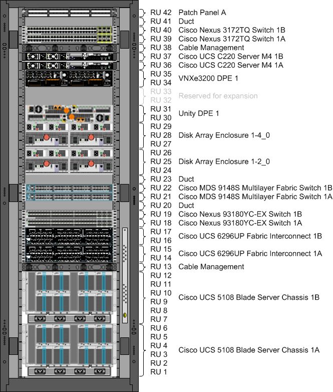
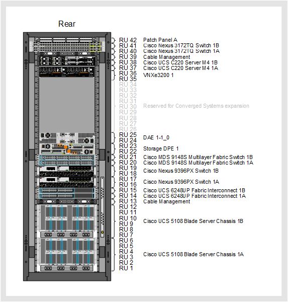
Base configurations
The base configuration of the Converged System contains the minimum set of compute and storage
components, and fixed network resources. These components are integrated within one or more 28-inch
42 RU cabinets.
Within the base configuration, customize the following hardware aspects:
Hardware How it can be customized
Compute • Cisco UCS B-Series and C-Series M4 or M5 Blade Servers
• Minimum of four Cisco UCS blade servers
• Maximum of 256 Cisco UCS blade servers (The maximum server value is
based on storage array front-end connectivity support and physical chassis
slots.)
• Minimum of 2 Cisco UCS 5108 Blade Server Chassis
Edge servers (with optional Four to six Cisco UCS B-Series Blade Servers or Cisco UCS C-Series Blade
VMware NSX) Servers, including the B2x0 M4 or B2x0 M5 with VIC 1340, VIC 1380, VIC
1385, or VIC 1387.
7 | System overviewHardware How it can be customized
Network • One pair of Cisco MDS 9148S Multilayer Switches, or one pair of Cisco
MDS 9396S Multilayer Fabric Switch, or one pair of Cisco MDS 9706
Multilayer Directors
• One pair of Cisco Nexus 93180YC-EX Switches or one pair of Cisco
9396PX Switches
• One pair of Cisco Nexus 3172TQ Switches
Storage • Dell EMC Unity 300 - up to 150 drives
• Dell EMC Unity 400 - up to 250 drives
• Dell EMC Unity 500 - up to 500 drive
• Dell EMC Unity 600 - up to 1000 drives
• Dell EMC Unity 300F - up to 150 drives
• Dell EMC Unity 400F - up to 250 drives
• Dell EMC Unity 500F - up to 500 drives
• Dell EMC Unity 600F - up to 1,000 drives
• Dell EMC Unity 350F - up to 150 drives
• Dell EMC Unity 450F - up to 250 drives
• Dell EMC Unity 550F - up to 500 drives
• Dell EMC Unity 650F - up to 1,000 drives
Management hardware options AMP-2 is available in multiple configurations that use their own resources to run
workloads without consuming resources on the Converged System.
AMP-3S is available in a single configuration that uses its own resources to run
workloads without consuming resources on the Converged System.
Depending upon the configuration, the following maximums apply:
Component Maximum configurations
Cisco UCS 62xxUP Fabric The maximum number of Cisco B-Series Blade Server Chassis with 4 Cisco UCS
Interconnects domains is:
• 32 for Cisco UCS 6248UP Fabric Interconnects
• 64 for Cisco UCS 6296UP Fabric Interconnects
Maximum blades are as follows:
• Half-width = 256
• Full-width = 256
• Double-height = 128 (The maximum server value is based on storage array
front-end connectivity support and physical chassis slots.)
Together, the components offer balanced CPU, I/O bandwidth, and storage capacity relative to the
compute and storage arrays in the Converged System. All components have N+N or N+1 redundancy.
Related information
Storage layer (see page 19)
Scaling up compute resources (see page 10)
System overview | 8Converged System configurations
The initial size of the Converged System is determined by the total number of supported servers across
all Cisco UCS domains.
The number of servers determines the minimum number of 16 Gb FC ports on the Dell EMC Unity Hybrid
or Dell EMC Unity All-Flash storage array. The options for FC connectivity on the storage array are
through the integrated converged network adapter (CNA) ports or the addition of FC I/O modules.
Each Dell EMC configuration for Dell EMC Unity Hybrid and All-Flash storage arrays depends on the
number of FC ports on each SP.
The following table describes the Dell EMC size configurations that support the Dell EMC Unity storage
array:
Dell EMC configuration Total servers Number of FC ports per SP
Extra small 32 2 (CNA ports only)
Small 64 4 (one 16 Gb FC SLIC)
Medium 128* 6 (CNA and one 16 Gb FC SLIC)
Large 192* 8 (two 16 Gb FC SLICs)
Extra large 256* 10 (CNA and two 16 Gb FC SLICs)
*The Dell EMC Unity 300, 300F, and 350F storage arrays support up to 128 hosts due to initiator record
limitations.
The large and extra-large configurations consume both I/O module slots that prevents use of the backend
bus expansion module (4 port, 12 Gb SAS). The extra-large configuration consumes both I/O module
slots and the CNA ports. This eliminates use of NAS file services without the use of the integrated 10
GbE-BaseT ports (RJ45). These ports do not integrate into Converged Systems without modifications to
network hardware that would require an impact assessment.
Only the Dell EMC Unity 500(F), 550F, 600(F), and 650F storage arrays allow bus expansion.
The maximum number of supported Cisco UCS domains is based on the array connectivity configuration.
Each domain consists of two Cisco UCS 62xxUP fabric interconnects.
The following table provides the maximums for each Dell EMC configuration:
Dell EMC Domains Chassis Blades
configuration
Half-width Full-width Double-height
Extra small* 1 16 32 32 32
Small 2 32 64 64 64
Medium 3 48 128 128 96
Large 4 64 192 192 128
Extra large 4 64 256 256 128
* Does not support the Cisco UCS 6296UP Fabric Interconnects.
9 | System overviewThe storage layer section of this document contains a description of CNA ports and FC options.
Scaling up compute resources
Compute resources can be scaled to meet increasingly stringent requirements. The maximum supported
configuration differs based on core components.
Add uplinks, blade packs, and chassis activation kits to enhance Ethernet and FC bandwidth when the
Converged Systems are built or deployed.
Blade packs
Cisco UCS blades are sold in packs of two and include two identical Cisco UCS blades. The base
configuration of each Converged System includes two blade packs. The maximum number of blade packs
depends on the type of Converged System. Each blade type must have a minimum of two blade packs as
a base configuration and can be increased in single blade pack increments.
Each blade pack includes the following license packs:
• VMware vSphere ESXi
• Cisco Nexus 1000V Series Switches (Cisco Nexus 1000V Advanced Edition only)
• PowerPath/VE
License packs for VMware vSphere ESXi, Cisco Nexus 1000V Series Switches, and
PowerPath are not available for bare metal blades.
Chassis activation kits
Power supplies and fabric extenders for all chassis are populated and cabled. All required twinax cables
and transceivers are populated.
As more blades are added and additional chassis are required, chassis activation kits are automatically
added to an order. Each kit contains software licenses to enable additional fabric interconnect ports.
Only enough port licenses for the minimum number of chassis to contain the blades are ordered. Chassis
activation kits can be added up-front to allow for flexibility in the field or to initially spread the blades
across a larger number of chassis.
Related information
Base configurations (see page 7)
Scaling up storage resources
To scale up storage resources, add block I/O bandwidth, RAID packs, and DAE packs between the
compute and storage resources. I/O bandwidth and RAID packs can be added when the Converged
System is built and after it is deployed.
System overview | 10I/O bandwidth expansion
RAID packs
Storage capacity can be increased by adding RAID packs. Each pack contains a number of drives of a
given type, speed, and capacity. The number of drives in a pack depends upon the RAID level that it
supports.
The number and types of RAID packs to include in the Converged System are based upon the following:
• The number of storage pools that are needed.
• The storage tiers that each pool contains, and the speed and capacity of the drives in each tier.
The following table lists tiers, supported drive types, and supported speeds and capacities.
The speed and capacity of all drives within a given tier in a given pool must be the same.
The following table describes each supported RAID protection level and Dell EMC best practice. The
RAID protection level for the different pools can vary.
RAID Description
protection
level
RAID 1/0 • A set of mirrored drives.
• Offers the best overall performance of the three supported RAID protection levels.
• Offers robust protection. Can sustain double-drive failures that are not in the same mirror set.
• Lowest economy of the three supported RAID levels since usable capacity is only 50% of raw
capacity.
RAID 5 • Block-level striping with a single parity block, where the parity data is distributed across all of the
drives in the set.
• Offers the best mix of performance, protection, and economy.
• Has a higher write performance penalty than RAID 1/0 because multiple I/Os are required to
perform a single write.
• With single parity, can sustain a single drive failure with no data loss. Vulnerable to data loss or
unrecoverable read errors on a track during a drive rebuild.
• Highest economy of the three supported RAID levels. Usable capacity is 80% of raw capacity or
better.
• Dell EMC best practice for extreme performance and performance tiers.
RAID 6 • Block-level striping with two parity blocks, distributed across all of the drives in the set.
• Offers increased protection and read performance comparable to RAID 5.
• Has a significant write performance penalty because multiple I/Os are required to perform a
single write.
• Economy is very good. Usable capacity is 75% of raw capacity or better.
• Dell EMC best practice for capacity tier.
There are RAID packs for each RAID protection level/tier type combination. The RAID levels dictate the
number of drives that are included in the packs. RAID 5 or RAID 1/0 is for performance and extreme
performance tiers and RAID 6 is for the capacity tier.
11 | System overviewThe following table lists RAID protection levels and the number of drives in the pack for each level:
RAID protection level Number of drives per RAID pack
RAID 1/0 8 (4 data + 4 mirrors)
RAID 5 5 (4 data + 1 parity)
RAID 6
DAE packs
If the number of RAID packs in Converged Systems is expanded, more DAEs might be required. DAEs
are added in packs. The number of DAEs in each pack is equivalent to the number of back-end buses in
the storage array in the Converged System. If an 80-drive DAE is configured in the system, balance
buses as evenly as possible.
There are three types of DAEs:
• 2 RU 25 slot DAE for 2.5-inch disks
• 3 RU 15 slot DAE for 3.5-inch disks
• 3 RU 80 slot DAE for 2.5-inch disks
A DAE pack can contain a mix of DAE sizes if the total DAEs in the pack equals the number of buses. To
ensure the loads are balanced, the physical disks are spread across the DAEs in accordance with best
practice guidelines.
When adding the 80 slot DAE, limited configurations are available due to slot maximums in
each system.
Network topology
In segregated network architecture, LAN and SAN connectivity is segregated into separate switch fabrics.
10 Gb connectivity
LAN switching uses the Cisco Nexus 93180YC-EX or Cisco Nexus 9396PX. SAN switching uses the
Cisco MDS 9148S Multilayer Fabric Switch, Cisco MDS 9396S 16G Multilayer Fabric Switch, or Cisco
MDS 9706 Multilayer Director.
The compute layer connects to both the Ethernet and FC components of the network layer. Cisco UCS
fabric interconnects connect to the Cisco Nexus switches in the Ethernet network through port channels,
based on 10 GbE links, and to the Cisco MDS switches through port channels made up of multiple 8 Gb
FC links.
The storage layer consists of an Dell EMC Unity Hybrid or Dell EMC Unity All-Flash storage array. The
front-end IO ports connect to the Cisco MDS switches within the network layer over 16 Gb FC links and to
the Cisco Nexus switches over 10GbE port channels.
Segregated network architecture
The storage layer consists of a Dell EMC Unity storage array.
System overview | 12The front-end IO modules connect to the Cisco MDS switches within the network layer over 16 Gb FC
links. Refer to the appropriate Dell EMC Release Certification Matrix for a list of what is supported on your
Converged System.
The following illustration shows a segregated block storage configuration for the 10 Gb based Converged
System:
The transceiver choices are 1 GbE, 10 GbE, copper or optical, SW or LW.
Unified storage
Unified storage contains Cisco MDS switches and Cisco Nexus switches to provide switching and routing
between the compute and storage layers within a Converged System, and between the Converged
System and the external network.
The following illustration shows a unified storage configuration.
13 | System overviewThe External IP Network connects to the Cisco Nexus Switch with the Transceiver Choice. The
Cisco UCS Fabric Interconnect connects to the Cisco USC Blade Server Chassis with
Converged Ethernet.
SAN boot storage configuration
VMware vSphere ESXi hosts always boot over the FC SAN from a 10 GB boot LUN (VMware vSphere
6.0) which contains the hypervisor's locker for persistent storage of logs and other diagnostic files. The
remainder of the storage can be presented as VMFS data stores or as raw device mappings.
VMware vSphere ESXi hosts always boot over the FC SAN from a 15 GB boot LUN (VMware vSphere
6.5), which contains the hypervisor's locker for persistent storage of logs and other diagnostic files. The
remainder of the storage can be presented as VMFS data stores or as raw device mappings.
System overview | 14Compute layer
Compute overview
Cisco UCS B- and C-Series Blade Servers installed in the Cisco UCS server chassis provide computing
power within Converged Systems.
Fabric extenders (FEX) within the Cisco UCS server chassis connect to fabric interconnects (FIs) over
converged Ethernet. Up to eight 10 GbE ports on each FEX connect northbound to the FIs regardless of
the number of blades in the server chassis. These connections carry IP and FC traffic.
Dell EMC has reserved some of the FI ports to connect to upstream access switches within the
Converged System. These connections are formed into a port channel to the Cisco Nexus switches, and
carry IP traffic destined for the external network links. In a unified storage configuration, this port channel
can also carry NAS traffic to the within the storage layer.
Each FI also has multiple ports reserved by Dell EMC for FC ports. These ports connect to Cisco SAN
switches. These connections carry FC traffic between the compute layer and the storage layer. SAN port
channels carrying FC traffic are configured between the FIs and upstream Cisco MDS switches.
Cisco UCS
The Cisco UCS data center platform unites compute, network, and storage access. Optimized for
virtualization, the Cisco UCS integrates a low-latency, lossless 10 Gb/s Ethernet unified network fabric
with enterprise-class, x86-based Cisco UCS B-Series Servers.
Converged Systems powered by Cisco UCS offer the following features:
• Built-in redundancy for high availability
• Hot-swappable components for serviceability, upgrade, or expansion
• Fewer physical components than in a comparable system built piece by piece
• Reduced cabling
• Improved energy efficiency over traditional blade server chassis
Compute connectivity
Cisco UCS B- and C-Series Blades installed in the Cisco UCS chassis provide computing power in a
Converged System.
Fabric extenders (FEX) in the Cisco UCS chassis connect to Cisco fabric interconnects (FIs) over
converged Ethernet. Up to eight 10 GbE ports on each Cisco UCS fabric extender connect northbound to
the fabric interconnects, regardless of the number of blades in the chassis. These connections carry IP
and storage traffic.
15 | Compute layerCisco Trusted Platform Module
Cisco Trusted Platform Module (TPM) provides authentication and attestation services that provide safer
computing in all environments.
Cisco TPM is a computer chip that securely stores artifacts such as passwords, certificates, or encryption
keys that are used to authenticate remote and local server sessions. Cisco TPM is available by default as
a component in the Cisco UCS B- and C-Series blade servers, and is shipped disabled.
Only the Cisco TPM hardware is supported, Cisco TPM functionality is not supported. Because making
effective use of the Cisco TPM involves the use of a software stack from a vendor with significant
experience in trusted computing, defer to the software stack vendor for configuration and operational
considerations relating to the Cisco TPM.
Related information
www.cisco.com
Cisco UCS fabric interconnects
Cisco UCS fabric interconnects provide network connectivity and management capability to the Cisco
UCS blades and chassis.
VMware NSX
This VMware NSX feature uses Cisco UCS 6296UP Fabric Interconnects to accommodate the required
port count for VMware NSX external connectivity (edges).
Disjoint Layer 2 configuration
Traffic is split between two or more different networks at the fabric interconnect in a Disjoint Layer 2
configuration to support two or more discrete Ethernet clouds.
Cisco UCS servers connect to two different clouds. Upstream Disjoint Layer 2 networks allow two or more
Ethernet clouds that never connect to be accessed by VMs located in the same Cisco UCS domain.
The following illustration provides an example implementation of Disjoint Layer 2 networking into a Cisco
UCS domain:
Compute layer | 16vPCs 101 and 102 are production uplinks that connect to the network layer of the Converged System.
vPCs 105 and 106 are external uplinks that connect to other switches.
If using Ethernet performance port channels (103 and 104, by default), port channels 101 through 104 are
assigned to the same VLANs.
Disjoint Layer 2 network connectivity can also be configured with an individual uplink on each fabric
interconnect.
Bare metal support policy
Since many applications cannot be virtualized due to technical and commercial reasons, Converged
Systems support bare metal deployments, such as non-virtualized operating systems and applications.
17 | Compute layerWhile it is possible for Converged Systems to support these workloads (with the following caveats), due to
the nature of bare metal deployments, Dell EMC can only provide reasonable effort support for systems
that comply with the following requirements:
• Converged Systems contain only Dell EMC published, tested, and validated hardware and
software components. The Release Certification Matrix provides a list of the certified versions of
components for Converged Systems.
• The operating systems used on bare metal deployments for compute components must comply
with the published hardware and software compatibility guides from Cisco and Dell EMC.
• For bare metal configurations that include other hypervisor technologies (Hyper-V, KVM, etc.)
those hypervisor technologies are not supported by Dell EMC. Dell EMC support is provided only
on VMware Hypervisors.
Dell EMC reasonable effort support includes Dell EMC acceptance of customer calls, a determination of
whether a Converged System is operating correctly, and assistance in problem resolution to the extent
possible.
Dell EMC is unable to reproduce problems or provide support on the operating systems and applications
installed on bare metal deployments. In addition, Dell EMC does not provide updates to or test those
operating systems or applications. The OEM support vendor should be contacted directly for issues and
patches related to those operating systems and applications.
Compute layer | 18Storage layer
Storage overview
Dell EMC Unity Hybrid and Dell EMC Unity All-Flash storage arrays provide a scalable hardware design
and advanced software capabilities using flash drives and spinning disks.
The following Dell EMC Unity Hybrid and All-Flash storage array models are available:
Dell EMC Unity Hybrid Dell EMC Unity All-Flash
300 300F and 350F
400 400F and 450F
500 500F and 550F
600 600F and 650F
Dell EMC Unity storage arrays support midrange storage solutions that include transactional workloads
such as databases, virtualized servers, and multiple workload consolidation. Dell EMC Unity is a unified
solution that supports block and file environments with the flexibility to configure a system, capacity
points, and data protection options.
The Dell EMC Unity 300 to 600 and 300F to 600F storage arrays share the same system hardware, but
the all-flash storage arrays contain only flash drives. The Dell EMC Unity 350F to 650F storage arrays
have updated system hardware and contain only flash drives. The following table lists the processors and
memory per storage processor:
Storage array Processor (per SP) Memory (per SP)
300 and 300F Intel E5-2603v3 24GB (3x 8GB or 16GB) @ 1600MHz
6-core, 1.6GHz
400 and 400F Intel E5-2630v3 48GB (3x 16GB) @ 1600MHz
8-core, 2.4GHz
500 and 500F Intel E5-2660v3 64GB (4x 16GB) @ 1866MHz
10-core, 2.6GHz
600 and 600F Intel E5-2680v3 128GB (4x 32GB) @ 1866MHz
12-core, 2.5GHz
350F Intel E5-2603v4 48GB (3x 16GB) @ 1866MHz
6-core, 1.7GHz
450F Intel E5-2630v4 64GB (4x 16GB) @ 2133MHz
10-core, 2.2GHz
550F Intel E5-2660v4 128GB (4x 32GB) @ 2400MHz
14-core, 2.0GHz
650F Intel E5-2680v4 256GB (4x 64GB) @ 2400MHz
14-core, 2.4GHz
Dell EMC Unity storage arrays support integrated block and file storage and are optimized for VMware
virtualized applications. They feature flash drives for extendable cache in the virtual storage pools.
19 | Storage layerAutomation features include self-optimized storage tiering and application-centric replication. Dell EMC
Unity All-Flash supports high density solid-state disks (SSDs) including 3D NAND triple level cell (TLC)
drives.
Regardless of the storage protocol implemented, Converged Systems can include cabinet space, cabling,
and power to support the hardware. Dell EMC Unity storage processors include software storage
controllers that eliminate the need for separate hardware to perform file sharing and facilitate moving from
block storage to unified storage avoiding hardware changes.
Hybrid and All-Flash components
The Dell EMC Unity Hybrid and Dell EMC Unity All-Flash storage arrays contain the disk processor
enclosure (DPE) that house the redundant storage processors (SPs).
The DPE provides slots for two SPs and integrated drive slots for 25 2.5-inch drives or 12 3.5-inch drives.
Each SP contains the following components:
• Single socket CPU
• Three to four DDR5 DIMM slots, depending on the model
• Internal battery backup unit (BBU)
• Two integrated 10 GbE BaseT ports (RJ45)
• Two integrated converged network adapter (CNA) ports (SFP+ or twinax)
— 10 GbE optical
— 16 Gb FC
• Two integrated 12 Gb SAS ports for DAE connections
• Two slots for additional I/O modules (SLICs)
— Four port 12 Gb SAS (bus expansion)
— Four port 16 Gb FC
— Four port Ethernet 10 GbE optical
— Two port Ethernet 10 GbE Optical (full iSCSI offload)
The integrated Ethernet ports and the Ethernet I/O modules supply Network Attached Storage (NAS) to
associated hosts for file system access. The SPs run virtual NAS servers for file sharing.
The VxBlock System 350 uses the 10GbE optical option for NAS usage.
DAEs contain individual disk drives and are available in the following configurations:
• 2 RU model that can house 25 2.5-inch disks
• 3 RU model that can house 15 3.5-inch disks (hybrid models only)
Storage layer | 20• 3 RU model that can house 80 2.5-inch disks
Differences between Dell EMC Unity models
The following table provides the specifications among the Dell EMC Unity storage arrays:
Component 300 350F 400 450F 500 550F 600 650F
300F 400F 500F 600F
Processor per SP 6 core, 6 core, 8 core, 10 core, 10 core, 14 core, 12 core, 14 core,
1.6 GHz 1.7 GHz 2.4 GHz 2.2 GHz 2.6 GHz 2.0 GHz 2.5 GHz 2.4 GHz
Memory 48 48 96 64 128 128 256 256
(GB per storage array)
Maximum drive count 150 150 250 250 500 500 1000 1000
Maximum FAST cache 800 GB - 1.2 TB - 3.2 TB - 6 TB -
(HFA only )
Bus expansion NA NA NA NA 4 port, 4 port, 4 port, 4 port,
(x4 lane configuration) 12 Gb/s 12 Gb/s 12 Gb/s 12 Gb/s
SAS SAS SAS SAS
Bus expansion NA NA NA NA 4 port, 4 port, 4 port, 4 port,
(x8 lane configuration) 12 Gb/s 12 Gb/s 12 Gb/s 12 Gb/s
SAS SAS SAS SAS
LUNs 1000 1000 1500 1500 2000 2000 6000 6000
Pool LUN size (TB) 256 256 256 256 256 256 256 256
File systems 500 1000 750 1500 1000 2000 1500 4000
File system size (TB) 256 256 256 256 256 256 256 256
Pools 20 20 30 30 40 40 100 100
NAS servers 90 90 90 128 128 128 128 256
Remote replication
Dell EMC Unity Hybrid and All-Flash storage arrays provide native support for both synchronous and
asynchronous remote replication and support for RecoverPoint to provide remote replication.
For block storage configurations, Converged Systems can be upgraded to include RecoverPoint that
provides continuous data protection and continuous remote replication for on-demand protection and
recovery to any point-in-time. RecoverPoint advanced capabilities include policy-based management,
application integration, and bandwidth reduction. RecoverPoint is included in the Dell EMC Unity All-Flash
All-Inclusive Base Software and the Dell EMC Unity Hybrid All-Inclusive Essentials Software packages.
Implementing Recoverpoint
To implement RecoverPoint within a Converged System, add two or more RecoverPoint Appliances
(RPAs) in a cluster to the Converged System. This cluster can accommodate approximately 80 MBps
sustained throughput through each RPA.
21 | Storage layerTo ensure proper sizing and performance of an RPA solution, Dell EMC works with a Technical
Consultant. They collect information about the data to be replicated, as well as data change rates, data
growth rates, network speeds, and other information that is needed to ensure that all business
requirements are met.
Related information
Scaling up storage resources (see page 10)
Storage features support
The operating environment for Dell EMC Unity hardware or capabilities provides support for storage
features.
Support for array hardware or capabilities
The following table lists the supported capabilities for Dell EMC Unity operating environments:
Capability Description
Virtual NAS Servers (multi-LDAP support) Provides security and segregation for service provider
environmental clients.
Fully-automated storage tiering for virtual FAST VP places highly-accessed blocks of data on the faster tier
pools (FAST VP) only for Dell EMC Unity in a pool. FAST VP is important in hybrid pools which contain data
Hybrid storage arrays with significant skew (usage and capacity).
Dell EMC Unity snapshots Dell EMC Unity snapshots are used for individual LUNs or
consistency groups. Dell EMC recommends including extreme
performance flash drives in pools where snapshots are active.
Quality of Service (QoS) QoS settings can be used to limit the amount of resources used by
a particular application or host. These settings can prevent an
application from impacting other applications running on the same
array.
Data At Rest Encryption (D@RE) D@RE is used by the storage processors to encrypt data prior to
writing it to disk.
External NFS and CIFS access The following guidelines must be followed to present CIFS and
NFS shares to external clients:
• Dedicated Ethernet ports are required for host access outside
of Converged Systems
• Shares cannot be mounted internally by Converged System
hosts and externally to the Converged System at the same
time.
Remote replication Dell EMC Unity supports both synchronous and asynchronous
replication natively. Dell EMC also provides support for
RecoverPoint Basic and RecoverPoint for VMs.
System health checks Allows you to determine the status of an array prior to any upgrade
activities. The health check code can be upgraded independently
from the system code.
Storage layer | 22Capability Description
Remote support Secure Remote Services (Virtual Edition) provides:
• Proactive creation of service requests
• Remote dial-in/dial-out connectivity
• Secure large file transfers
• Usage/license reporting
File system quotas Quotas allow regulation of storage consumption through soft and
hard limits on user or tree structures.
CloudIQ Cloud-based Software as a Service (SaaS) to monitor and service
Dell EMC Unity systems. Inform the users about issues before they
occur. Provide simple, guided remediation to expedite resolution.
Data-In-Place Conversions Data-In-Place (DIP) conversion is a procedure used to upgrade
storage processors while leaving all data and configurations intact.
IP Multi-Tenancy Provides network isolation for file-based tenants. Each tenant has
its own network namespace. Enables multiple tenants to use the
same IP addresses.
Data Reduction Data Reduction combines compression and deduplication to
reduce the amount of physical storage required to store datasets.
Local LUN Move On a single Dell EMC Unity system, native support to move LUNs
between pools or within the same pool.
Native SAN Copy Import Import of block resources from a VNX1/VNX2 system to Dell EMC
Unity GA can be achieved through SAN Copy.
Dell EMC Unity File Import VNX1/VNX2 systems have options for file migration to Dell EMC
Unity. Native support for NFS File Import.
Hardware features
Dell EMC recommends the following best practices for Dell EMC Unity hardware.
DAEs/disks
• Two integrated 12 Gb SAS ports support 20 DAEs, up to 500 drives. Each port is capable of
handling over 250,000 IOPS.
• Dell EMC Unity 600 has a maximum of 1,000 drives; an SAS bus expansion module is necessary.
• Balance DAEs across available SAS buses:
— Two Integrated SAS ports: order DAEs in multiples of two, including DPE as one.
— Bus expansion module: order DAEs in multiples of six, including DPE as one.
• Minimum five percent flash in every multi-tier pool
• Drives should only be separated into separate pools if a different performance model is required.
— For example, all VMware vSphere ESXi boot and data LUNs can reside in the same pool.
23 | Storage layer— Drives for file access (NAS) can also be in the same pool, provided the I/O performance
requirements are the same.
— Fewer, larger pools will increase the overall performance of the array.
I/O modules
• Each array must have at least two 16 Gb FC ports (integrated CNA or I/O module)
• Add FC I/O modules to increase the scalability of hosts.
• The following I/O modules are supported:
— 12 Gb SAS backend (four port): increased bus capacity
— 16 Gb FC front end (four port): block access
— 10 GbE optical (four port): file access
Other modules do not easily integrate in Converged Systems and require an impact assessment.
FAST cache
• FAST cache is available in Dell EMC Unity Hybrid only.
• Dell EMC recommends placing available flash drives in disk pools prior to FAST cache to take
advantage of flash for metadata acceleration, snapshots, and replication.
• Use FAST cache for pools that do not contain extreme performance tier drives.
FAST VP
• Use multi-tier pools where possible and when performance is required. Dell EMC recommends a
minimum of five percent Extreme Performance (Flash) capacity.
• Create as few pools as possible to support the different I/O performance requirements. Only
create a separate pool when the I/O profile for an application differs significantly from the other
applications. For example, an application with fairly static data may require a capacity tier-only
pool.
• All LUNs in the pool should be configured with tiering policy Start High then Auto-Tier unless the
data profile for the LUN requires highest available or lowest available.
• VMware vSphere ESXi boot and data LUNs should be allocated from the same pool.
Network Attached Storage
• Internal shares/exports are defined as data used by resources inside the Converged System as
either VMware vSphere ESXi datastores or as file system mounts for guest operating systems.
• External shares/exports are defined as data used by resources outside of the Converged System.
• Internal and external file systems can be provided by the same array as long as there are
sufficient Ethernet ports available to provide separate LACP connections. Each LACP pair needs
a connection to each LAN switch in the Converged System. Both SPs must have the same LACP
configurations. For example, if the integrated CNA ports are configured for 10GbE, then Ethernet
Storage layer | 24port four should connect to LAN switch A and port five should connect to LAN switch B. Both SPs
should be cabled the same. These two ports (Ethernet port four and five) should be used to
create an LACP pair. This LACP pair can then be used by internal or external NAS servers, but
not both. An additional LACP pair must be created to allow both internal and external NAS
Servers.
• For internal shares, create two different NAS servers, one hosted by SP-A and the other hosted
by SP-B. Each server hosts different file systems. Balance the file systems across the NAS
servers. Additional NAS servers can be created as necessary for different VLANs, but always in
pairs for balance across the SPs.
• For external shares create two different NAS servers, one hosted by SP-A and the other hosted
by SP-B. Balance the file systems across the external NAS servers. Additional NAS servers can
be created as necessary, but always in pairs for balance.
Software licensing
Dell EMC recommends the following best practices for Dell EMC Unity software.
• Dell EMC Unity All-Flash requires the All-Inclusive Base software license.
• Dell EMC Unity Hybrid requires the All-Inclusive Essentials software license to use FAST cache,
FAST VP, and Remote Replication.
25 | Storage layerNetwork layer
LAN and SAN make up the network layer.
LAN layer
The LAN layer of the Converged System
The Cisco Nexus switches provide 10 GbE connectivity:
• Between internal components
• To the site network
• To the AMP-2 through redundant connections between AMP-2 and the Cisco Nexus 9000 Series
Switches
• To the AMP-3S through redundant connections between AMP-3S and the Cisco Nexus 9000
Series Switches. AMP-3S is only supported with the Cisco Nexus 93180YC-EX.
The following table shows LAN layer components:
Component Description
Cisco Nexus 93180YC-EX • 1 RU appliance
• Supports 48 fixed 10/25 Gbps SFP+ ports and 6 fixed 40/100 Gbps
QSFP+ ports
• No expansion modules available
Cisco Nexus 9396PX Switch • 2 RU appliance
• Supports 48 fixed, 10 Gbps SFP+ ports and 12 fixed, 40 Gbps QSFP
+ ports
• No expansion modules available
Management network layer
The management network layer of the VxBlock/Vblock 350 includes at least one pair of Cisco Nexus
3172TQ management switches.
If more than one pair of Cisco Nexus 3172TQ switches is required, a pair of Cisco 9336C-FX switches is
introduced to aggregate management traffic.
The following table shows management layer switch options.
Component Description
Cisco Nexus 3172TQ Switch • 1 RU appliance
• Supports 48 fixed, 100 Mbps/1000 Mbps/10 Gbps
twisted pair connectivity ports and 6 fixed, 40 Gbps
QSFP+ ports for the
• Management layer of the Converged System
Network layer | 26Cisco Nexus 3172TQ Switch - management networking
Each Cisco Nexus 3172TQ Switch provides 48 100 Mbps/1000 Mbps/10 Gbps twisted pair connectivity
and six 40 GbE QSFP+ ports.
Cisco Nexus 3172TQ Switch on AMP-2 and AMP-3S
The following table shows core connectivity for the Cisco Nexus 3172TQ Switch for management
networking and reflects the base for two servers:
The remaining ports in the Cisco Nexus 3172TQ Switch provide support for additional domains and their
necessary management connections.
Cisco Nexus 93180YC-EX Switch or Cisco Nexus 9396PX Switch -
segregated networking
The Cisco Nexus 93180YC-EX Switch provides 48 10/25 Gbps SFP+ ports and six 40/100 Gbps QSFP+
uplink ports. The Cisco Nexus 9396PX Switch provides 48 SFP+ ports used for 1 Gbps or 10 Gbps
connectivity and 12 40 Gbps QSFP+ ports.
The following table shows core connectivity for the Cisco Nexus 93180YC-EX Switch or Cisco Nexus
9396PX Switch with segregated networking:
Feature Used ports Port speeds Media
Uplinks from FI 8 10 GbE Twinax
Uplinks to customer core 8 (10 GbE)/2 (40 GbE) Up to 40 GbE SFP+/
QSFP+
vPC peer links 2 40 GbE Twinax
AMP-3S ESXi management** 6 10 GbE SFP+
**Only supported on Cisco Nexus 93180YC-EX.
The remaining ports in the Cisco Nexus 93180YC-EX Switch or Cisco Nexus 9396PX Switch provide
support for a combination of the following additional connectivity options:
Feature Available Port speeds Media
ports
RecoverPoint WAN links (one per appliance pair) 4 1 GbE GE T SFP+
Customer IP backup 8 1 GbE or 10 SFP+
GbE
Uplinks from Cisco UCS FIs for Ethernet BW enhancement 8 10 GbE Twinax
SAN layer
Two Cisco MDS 9148S Multilayer Fabric Switches, Cisco MDS 9706 Multilayer Directors, or Cisco MDS
9396S 16G Multilayer Fabric Switches that make up two separate fabrics to provide 16 Gbps of FC
connectivity between the compute and storage layer components.
27 | Network layerConnections from the storage components are over 16 Gbps connections.
With 10 Gbps connectivity, Cisco UCS fabric interconnects provide a FC port channel of four 8 Gbps
connections (32 Gbps bandwidth) to each fabric on the Cisco MDS 9148S Multilayer Fabric Switches and
can be increased to eight connections for 128 Gbps bandwidth. The Cisco MDS 9396S 16G Multilayer
Fabric Switch and Cisco MDS 9706 Multilayer Directors also support 16 connections for 128 Gbps
bandwidth per fabric.
The Cisco MDS switches provide:
• FC connectivity between compute and storage layer components
• Connectivity for backup and business continuity requirements (if configured)
Inter-Switch Links (ISLs) to the existing SAN or between switches is not permitted.
The following table shows SAN network layer components:
Component Description
Cisco MDS 9148S Multilayer Fabric • 1 RU appliance
Switch • Provides 12 to 48 line-rate ports for non-blocking 16 Gbps throughput
• 12 ports are licensed - additional ports can be licensed
Cisco MDS 9396S 16G Multilayer • 2 RU appliance
Fabric Switch • Provides 48 to 96 line-rate ports for non-blocking 16 Gbps throughput
• 48 ports are licensed - additional ports can be licensed in 12 port
increments
Cisco MDS 9706 Multilayer Director • 9 RU appliance
• Provides up to 12 Tbps front panel FC line rate non-blocking, system
level switching
• Dell EMC leverages the advanced 48 port line cards at line rate of
16 Gbps for all ports
• Consists of two 48 port line cards per director - up to two additional
48 port line cards can be added
• Dell EMC requires that 4 fabric modules are included with all Cisco
MDS 9706 Multilayer Directors for an N+1 configuration
• 4 PDUs
• 2 supervisors
Connectivity
Cisco MDS switches and directors have specific configurations for Dell EMC configurations for the Dell
EMC Unity storage arrays.
The following table shows connectivity for the Cisco MDS 9396S 16G Multilayer Fabric Switch, Cisco
MDS 9706 Multilayer Director, and Dell EMC configurations for the Dell EMC Unity storage arrays:
Dell EMC FC Domains Maximum FI PC Cisco Ports used with
configuration ports hosts one domain
Cisco MDS Cisco MDS
9396S/9706 9148S
Extra small 2 1 32 4,8,16 4 6-18
Network layer | 28Dell EMC FC Domains Maximum FI PC Cisco Ports used with
configuration ports hosts one domain
Cisco MDS Cisco MDS
9396S/9706 9148S
Small 4 2 64 4,8,16 4+4 8-20
Medium 6 3 128 4,8,16 4+4+4** 10-22
Large 8 4* 192 4,8,16 4+4+4** 12-24
Extra large 10 4 256 4,8,16 N/A 14-26
Cisco MDS 9148S Multilayer Fabric Switch
Converged Systems incorporate the Cisco MDS 9148S Multilayer Fabric Switch provide 12-48 line-rate
ports for non-blocking, 16 Gbps throughput. In the base configuration, 24 ports are licensed. Additional
ports can be licensed as needed.
The following table provides core connectivity for the Cisco MDS 9148S Multilayer Fabric Switch:
Feature Used ports Port speeds Media
FI uplinks 4 or 8 8 Gb SFP+
Cisco MDS 9396S 16G Multilayer Fabric Switch and Cisco MDS 9706
Multilayer Director
Converged Systems incorporate the Cisco MDS 9396S 16G Multilayer Fabric Switch and the Cisco MDS
9706 Multilayer Director to provide FC connectivity from storage to compute.
Cisco MDS 9706 Multilayer Directors provide 48-192 line-rate ports for non-blocking 16 Gbps throughput.
Port licenses are not required for the Cisco MDS 9706 Multilayer Director. The Cisco MDS 9706
Multilayer Director is a director-class SAN switch with four IOM expansion slots for 48-port 16 Gb FC line
cards. It deploys two supervisor modules for redundancy.
Cisco MDS 9396S 16G Multilayer Fabric Switches provide 48-96 line-rate ports for non-blocking, 16 Gbps
throughput. The base license includes 48 ports. Additional ports can be licensed in 12 port increments.
The Cisco MDS 9396S 16G Multilayer Fabric Switch is a 96-port fixed switch with no IOM modules for
port expansion.
29 | Network layerVirtualization layer
Virtualization components
VMware vSphere is the virtualization platform that provides the foundation for the private cloud. The core
VMware vSphere components are the VMware vSphere ESXi and VMware vCenter Server for
management.
VMware vSphere 6.0 includes a pair of Platform Service Controller Linux appliances to provide the SSO
service. Either the VMware vCenter Service Appliance or the VMware vCenter Server for Windows can
be deployed.
VMware vSphere 6.5 includes a pair of Platform Service Controller Linux appliances to provide the SSO
service. Starting from vSphere 6.5 VMware vCenter Server Appliance is the default deployment model for
vCenter Server.
The hypervisors are deployed in a cluster configuration. The cluster allows dynamic allocation of
resources, such as CPU, memory, and storage. The cluster also provides workload mobility and flexibility
with the use of VMware vMotion and Storage vMotion technology.
VMware vSphere Hypervisor ESXi
VMware vSphere Hypervisor ESXi runs on the AMP-2, AMP-3S, and uses VMware vSphere Server
Enterprise Plus.
This lightweight hypervisor requires little space to run (less than 6 GB of storage required to install) and
has minimal management overhead.
In some instances, the hypervisor may be installed on a 32 GB or larger Cisco FlexFlash SD Card
(mirrored HV partition). Beginning with VMware vSphere 6.x, all Cisco FlexFlash (boot) capable hosts will
be configured with a minimum of two 32GB or larger SD cards.
The compute hypervisor will support 4-6 10 GigE physical NICs (pNICS) on the VxBlock System VICs.
VMware vSphere ESXi does not contain a console operating system. The VMware vSphere Hypervisor
ESXi boots from Cisco FlexFlash (SD card) on AMP-2, AMP-3S,. For the compute blades, VMware
vSphere ESXi boots from the SAN through an independent FC LUN presented from the storage array.
The FC LUN also contains the hypervisor's locker for persistent storage of logs and other diagnostic files
to provide stateless computing within Converged Systems. The stateless hypervisor is not supported.
Cluster configuration
VMware vSphere ESXi hosts and their resources are pooled together into clusters. These clusters
contain the CPU, memory, network, and storage resources available for allocation to VMs. Clusters can
scale up to a maximum of 64 hosts for VMware vSphere 6.x. Clusters can support thousands of VMs.
The clusters can also support a variety of Cisco UCS blades running inside the same cluster.
Some advanced CPU functionality might be unavailable if more than one blade model is
running in a given cluster.
Virtualization layer | 30Datastores
Block level storage using VMFS or file level storage using NFS are supported datastores. The maximum
size per VMFS5 volume is 64 TB (50 TB VMFS3 @ 1 MB). The maximum VMDK file size is 62 TB. Each
host/cluster can support a maximum of 255 volumes.
Dell EMC optimizes the advanced settings for VMware vSphere ESXi hosts that are deployed in
Converged Systems to maximize the throughput and scalability of NFS datastores. Converged Systems
support a maximum of 256 NFS datastores per host.
Datastores (VMware vSphere 6.5)
Block level storage using VMFS or file level storage using NFS are supported datastores. The maximum
size per VMFS5 / VMFS6 volume is 64 TB (50 TB VMFS3 @ 1 MB). The maximum VMDK file size is 62
TB. Each host/cluster can support a maximum of 512 volumes.
Dell EMC optimizes the advanced settings for VMware vSphere ESXi hosts that are deployed in
Converged Systems to maximize the throughput and scalability of NFS datastores. Converged Systems
support a maximum of 256 NFS datastores per host.
Virtual networks
Alternatively, virtual networking is managed by a VMware vSphere Distributed Switch (VDS) with
comparable features to the Cisco Nexus 1000V where applicable. The VMware VDS option consists of a
VMware Standard Switch and a VMware VDS and uses a minimum of four uplinks presented to the
hypervisor.
Virtual networking in the AMP-2 uses standard virtual switches and is managed by the Cisco Nexus
1000V Series Switch. The Cisco Nexus 1000V Series Switch ensures consistent, policy-based network
capabilities to all servers in the data center by allowing policies to move with a VM during live migration.
This provides persistent network, security, and storage compliance.
The vNICs are equally distributed across all available physical adapter ports to ensure redundancy and
maximum bandwidth where appropriate. This provides general consistency and balance across all Cisco
UCS blade models, regardless of the Cisco UCS Virtual Interface Card (VIC) hardware. Thus, VMware
vSphere ESXi has a predictable uplink interface count. All applicable VLANs, native VLANs, MTU
settings, and QoS policies are assigned to the vNIC to ensure consistency in case the uplinks need to be
migrated to the VMware VDS after manufacturing.
Virtual networks (vSphere 6.5)
Virtual networking in the AMP-2S uses standard virtual switches and the Cisco Nexus 1000V is not
currently supported on the VMware vSphere 6.5 vCSA.
Alternatively, virtual networking is managed by a VMware vSphere Distributed Switch (VDS) with
comparable features to the Cisco Nexus 1000V where applicable. The VMware VDS option consists of a
VMware Standard Switch and a VMware VDS and uses a minimum of four uplinks presented to the
hypervisor.
The vNICs are equally distributed across all available physical adapter ports to ensure redundancy and
maximum bandwidth where appropriate. This provides general consistency and balance across all Cisco
UCS blade models, regardless of the Cisco UCS Virtual Interface Card (VIC) hardware. Thus, VMware
vSphere ESXi has a predictable uplink interface count. All applicable VLANs, native VLANs, MTU
settings, and QoS policies are assigned to the vNIC to ensure consistency in case the uplinks need to be
migrated to the VMware VDS after manufacturing.
31 | Virtualization layerYou can also read