Infinity Looper User's Guide
←
→
Page content transcription
If your browser does not render page correctly, please read the page content below
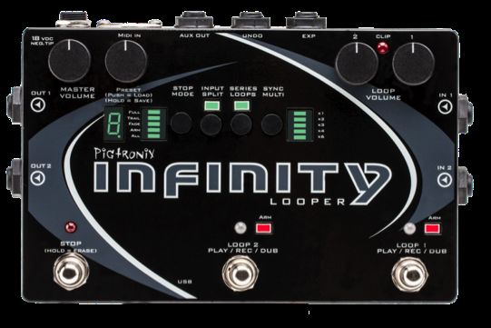
Infinity Looper
       User’s Guide

All contents c Absara Audio LLC 2014
Contents
Contents 1
1 Welcome to Infinity 5
2 Anatomy and Functions 7
2.1 Footswitches . . . . . . . . . . . . . . . . . . . . . . . 7
Loop 1 . . . . . . . . . . . . . . . . . . . . . . . . . . 7
Loop 2 . . . . . . . . . . . . . . . . . . . . . . . . . . 7
Stop . . . . . . . . . . . . . . . . . . . . . . . . . . . 8
2.2 Toggle Switches . . . . . . . . . . . . . . . . . . . . . 8
Stop Mode . . . . . . . . . . . . . . . . . . . . . . . . 8
Arm, All . . . . . . . . . . . . . . . . . . . . . 8
Full, Trail, Fade . . . . . . . . . . . . . . . . . 9
Input Split . . . . . . . . . . . . . . . . . . . . . . . . 9
Series Loops . . . . . . . . . . . . . . . . . . . . . . . 10
Sync Multi . . . . . . . . . . . . . . . . . . . . . . . . 10
2.3 Knobs . . . . . . . . . . . . . . . . . . . . . . . . . . 11
Master Volume . . . . . . . . . . . . . . . . . . . . . 11
Preset . . . . . . . . . . . . . . . . . . . . . . . . . . 12
Loop Volume 1 . . . . . . . . . . . . . . . . . . . . . 12
Loop Volume 2 . . . . . . . . . . . . . . . . . . . . . 12
2.4 Jacks . . . . . . . . . . . . . . . . . . . . . . . . . . . 13
DC Power . . . . . . . . . . . . . . . . . . . . . . . . 13
1CONTENTS 2
In 1 . . . . . . . . . . . . . . . . . . . . . . . . . . . . 13
In 2 . . . . . . . . . . . . . . . . . . . . . . . . . . . . 13
Out 1 . . . . . . . . . . . . . . . . . . . . . . . . . . 13
Out 2 . . . . . . . . . . . . . . . . . . . . . . . . . . 14
Aux Out . . . . . . . . . . . . . . . . . . . . . . . . . 14
Undo . . . . . . . . . . . . . . . . . . . . . . . . . . . 14
Expression . . . . . . . . . . . . . . . . . . . . . . . . 14
MIDI In . . . . . . . . . . . . . . . . . . . . . . . . . 15
USB . . . . . . . . . . . . . . . . . . . . . . . . . . . 15
2.5 LEDs . . . . . . . . . . . . . . . . . . . . . . . . . . . 16
Loop LEDs . . . . . . . . . . . . . . . . . . . . . . . . 16
Stop LED . . . . . . . . . . . . . . . . . . . . . . . . 16
Clip LED . . . . . . . . . . . . . . . . . . . . . . . . . 16
Multi-Segment Digit . . . . . . . . . . . . . . . . . . . 17
Decimal Point . . . . . . . . . . . . . . . . . . . . . . 17
3 Infinity Rules 19
3.1 Arm . . . . . . . . . . . . . . . . . . . . . . . . . . . 19
3.2 Record . . . . . . . . . . . . . . . . . . . . . . . . . . 19
3.3 Jump Record . . . . . . . . . . . . . . . . . . . . . . . 20
3.4 Play . . . . . . . . . . . . . . . . . . . . . . . . . . . 20
3.5 Stop . . . . . . . . . . . . . . . . . . . . . . . . . . . 20
3.6 Erase . . . . . . . . . . . . . . . . . . . . . . . . . . . 21
3.7 Overdub . . . . . . . . . . . . . . . . . . . . . . . . . 21
3.8 Sync Multi . . . . . . . . . . . . . . . . . . . . . . . . 22
3.9 Series Loops . . . . . . . . . . . . . . . . . . . . . . . 22
3.10 Series & Fade Modes . . . . . . . . . . . . . . . . . . 23
Trails . . . . . . . . . . . . . . . . . . . . . . . . . . . 23
Overdub . . . . . . . . . . . . . . . . . . . . . . . . . 23
3.11 Input Split . . . . . . . . . . . . . . . . . . . . . . . . 24
3.12 Presets . . . . . . . . . . . . . . . . . . . . . . . . . . 24
Loading . . . . . . . . . . . . . . . . . . . . . . . . . 24
Saving . . . . . . . . . . . . . . . . . . . . . . . . . . 25
Copying . . . . . . . . . . . . . . . . . . . . . . . . . 25
Erasing . . . . . . . . . . . . . . . . . . . . . . . . . . 26
3.13 Loop Aging . . . . . . . . . . . . . . . . . . . . . . . 26CONTENTS 3
3.14 Click Killer . . . . . . . . . . . . . . . . . . . . . . . . 27
3.15 Varispeed . . . . . . . . . . . . . . . . . . . . . . . . 28
3.16 Boot Options . . . . . . . . . . . . . . . . . . . . . . 30
Auto Zero Record . . . . . . . . . . . . . . . . . . . . 30
Mono Mixdown . . . . . . . . . . . . . . . . . . . . . 31
Stutter . . . . . . . . . . . . . . . . . . . . . . . . . . 31
Reformat . . . . . . . . . . . . . . . . . . . . . . . . . 32
4 Remote Switch Functions 33
4.1 Reverse . . . . . . . . . . . . . . . . . . . . . . . . . . 33
4.2 Undo . . . . . . . . . . . . . . . . . . . . . . . . . . . 34
4.3 Redo . . . . . . . . . . . . . . . . . . . . . . . . . . . 34
4.4 Rec→Overdub→Play . . . . . . . . . . . . . . . . . . 35
4.5 Instant Erase . . . . . . . . . . . . . . . . . . . . . . . 35
4.6 Varispeed Remote Control Menu . . . . . . . . . . . . 35
5 Expression Pedal Functions 39
5.1 Loop Volume . . . . . . . . . . . . . . . . . . . . . . 39
5.2 Loop Aging . . . . . . . . . . . . . . . . . . . . . . . 39
5.3 Varispeed . . . . . . . . . . . . . . . . . . . . . . . . 40
5.4 Expression Pedal Assignment . . . . . . . . . . . . . . 40
6 MIDI 43
6.1 MIDI Sync . . . . . . . . . . . . . . . . . . . . . . . . 43
6.2 Time Signature . . . . . . . . . . . . . . . . . . . . . 44
6.3 Commands That Sync to MIDI Clock . . . . . . . . . 44
Record and Play . . . . . . . . . . . . . . . . . . . . . 44
Stop . . . . . . . . . . . . . . . . . . . . . . . . . . . 44
Start . . . . . . . . . . . . . . . . . . . . . . . . . . . 44
Overdub . . . . . . . . . . . . . . . . . . . . . . . . . 45
6.4 Commands That Ignore MIDI Sync . . . . . . . . . . . 45
6.5 Full MIDI Mapping . . . . . . . . . . . . . . . . . . . 45
Cycle/Toggle . . . . . . . . . . . . . . . . . . . . . . . 46
Mapped . . . . . . . . . . . . . . . . . . . . . . . . . 46
Loop-Assignable . . . . . . . . . . . . . . . . . . . . . 46
Switch . . . . . . . . . . . . . . . . . . . . . . . . . . 46CONTENTS 4
MIDI Real-Time Messages . . . . . . . . . . . . . . . 47
Varispeed MIDI Note Control . . . . . . . . . . . . . . 48
7 Infinity Looper Application 49
8 Firmware Updates 51
8.1 Automatic Update Using the Looper Application . . . 51
8.2 Manual Firmware Update . . . . . . . . . . . . . . . . 52
9 Minimum and Maximum Loop Times 53
10 Acknowledgements 55
11 Pigtronix Limited Warranty 571. Welcome to Infinity
Pigtronix designed this pedal to be easy to use, yet vastly powerful and deeply musical. Think of it
as a foot-operated, digital version of a multi-track tape recorder. Eschewing the quantization and
delayed commands found in other looper pedals, the Pigtronix approach is to make all commands
instantaneous. The incredible processing power available in this pedal allows any action to be executed
with approximately 1 millisecond of latency and high fidelity recording at 24 bits/48 kHz. It is a mirror
of musical reality... what you put in is what you get out.
All loop audio on the Infinity Looper is stored to an on-board memory card and can be accessed via
the USB port located on the front of the unit. With the easy-to-use computer application that comes
pre-installed on the Infinity Looper pedal, you’ll be able to offload audio from−and upload audio
to−this pedal, via a PC or MAC computer.
Complementing the state-of-the-art digital platform of the Infinity Looper is a beautifully executed
analog input and output section that provides transparent pass-through audio as well as superior
headroom and discreet transistor-based limiting circuitry to prevent digital distortion, even at extreme
signal levels.
To put it succinctly, this looper sounds great! It will not ruin your tone like so many other looper
pedals that have come before.
Of all the innovative features found in the Infinity Looper, perhaps the most notable is the Sync Multi-
function, which allows Loop 2 to be a multiple length of Loop 1. This facilitates greater melodic
and harmonic development and frees the musician from the limits of their initial loop length. Along
with the inclusion of Series and Parallel loop operation, Auxiliary Output for loop audio, Input Split
capacity for recording different instruments on separate loops, Reverse, Undo, Redo, Loop Aging and
Varispeed, the Infinity Looper presets a near limitless set of possibilities for the creative musician.
The Infinity Looper was many years in the making and required a great deal of time and resources
to accomplish its ambitious goals. It’s been an emotional and psychologically challenging adventure
that resulted in a product we are exceptionally proud to present to the world of musicians interested
in creating loop-based music.
This pedal is dedicated to the memory of the great Les Paul, inventor of multi-track recording.
−Dave Koltai 11/2012
52. Anatomy and Functions
2.1 Footswitches
Loop 1
This footswitch controls the looping actions for Loop 1.
Pressing the Loop 1 footswitch at any time will arm Loop 1, illumi-
nating the corresponding red LED and indicating that Loop 1 is ready
to receive Play, Stop, Overdub and Undo commands. Loop 1 is armed
by default upon power up.
If there is no audio recorded on Loop 1, pressing the Loop 1 footswitch
will begin recording immediately. Once the loop is recording, pressing
the Loop 1 footswitch again will close the loop and begin playback.
During playback, pressing the Loop 1 footswitch will open an overdub
layer on Loop 1. Once an overdub is recording, pressing the Loop 1
footswitch again will close that overdub layer and continue playback.
When a loop has been recorded but is stopped, pressing the Loop 1
footswitch will resume playback from the beginning of the loop.
Loop 2
This footswitch controls the looping actions for Loop 2, and functions
the same way as the Loop 1 footswitch (see above).
6CHAPTER 2. ANATOMY AND FUNCTIONS 7 Stop Quickly pressing the Stop footswitch will stop audio playback on one or both loops, depending on the Arm/All setting (see below). Holding down the Stop footswitch for at least two seconds will cause loop audio to be erased from one or both loops, depending on the Arm/All setting. 2.2 Toggle Switches Stop Mode Quickly pressing the Stop Mode switch will toggle between Arm and All modes. Holding down the Stop Mode switch will toggle between Full, Trail and Fade modes. Arm, All In All mode, the Stop footswitch will stop playback on both loops. The All functionality also applies to the erase command. With ALL selected, holding down the Stop footswitch will erase both loops. The All functionality also applies to the Play command. Once the loops are stopped, hitting either loop footswitch will resume playback on both loops. In Arm mode, the Stop footswitch will stop playback only on the armed loop. The arm functionality also applies to the erase command. In Arm mode, holding down the Stop footswitch will erase only the armed loop (to stop both loops in Arm mode, hit the Stop footswitch
CHAPTER 2. ANATOMY AND FUNCTIONS                                    8

twice within 1 second). The Arm functionality also applies to the Play
command. When loops are stopped, pressing a loop footswitch will
only resume playback of the currently armed loop.
Some Remote Switch functions (page 33) also follow the Arm/All
setting.

Many MIDI CC/Note messages contain values that also specify Arm
or All control. For more information please see the description of the
MIDI implementation on page 43.

Full, Trail, Fade

In Full mode, audio will stop immediately when you push the Stop
footswitch.
In Trail mode, pressing the Stop footswitch will stop the loop audio
when it reaches the end of the current loop cycle.

In Fade mode, pressing the Stop footswitch will steadily decrease the
loop audio in volume until the end of the current loop cycle.

All three Stop modes obey the Arm/All setting.

In All mode, when audio has been recorded on both Loop 1 and Loop
2, Trail and Fade modes will be applied to the length of Loop 2.

Input Split

When Input Split is off, both loops record stereo audio coming from
Inputs 1 and 2.
When Input Split in on, Loop 1 gets audio from Input 1 only and Loop
2 gets audio from Input 2 only.
CHAPTER 2. ANATOMY AND FUNCTIONS                                        9

For more options and details, see the Infinity Rules Input Split section
on page 24.

Series Loops

When Series Loops is on, you are in Series mode. This means that
only one of the two loops can play at any given time. This is handy
for verse/chorus-type song structures.
When Series Loops is off, you are in Parallel mode. This means that
Loop 1 and Loop 2 can play together at the same time.

Sync Multi

Holding the Sync Multi switch will toggle Sync Multi on or off.
Quickly pressing the Sync Multi switch once Sync Multi is on, cycles
through the sync multiplier factor.

When Sync Multi is off, none of the sync multi lights are lit. In this
mode, the lengths of the two loops are unrelated and playback is not
synchronized.

When Sync Multi is on, the lengths of the two loops are synchronized.
The length of Loop 2 will be a multiple of the length of Loop 1, as
set by the multiplier factor indicated by the LED bar to the right of
the sync multi switch.
Loop 1 sets the initial length. Once recording on Loop 2 is initiated,
the Arm light will blink and it will wait to begin recording until the top
of the next loop cycle. Loop 2 will automatically stop recording and
begin playback when the proper length multiple has been reached.
CHAPTER 2. ANATOMY AND FUNCTIONS                                     10

You can alter the synchronization at any time while recording, by
manually closing Loop 2 with the Loop 2 footswitch. This will cause
Loop 2 to close at the end of the current loop cycle. The arm light
will blink to indicate that Loop 2 is about to close. To cancel this op-
eration, hit the Loop 2 footswitch again and it will continue recording
until the full multiplier factor has been reached.
Once Loop 2 is recorded, the Sync is locked to the multiplier you
have selected. It is possible to turn Sync on and off at this point, but
you must delete Loop 2 if you want to switch to a different multiplier
value.

Once Loop 2 is recorded, its length is fixed. However, turning Sync off
after that point allows you to start playback of Loop 2 at any time,
not just at the start of Loop 1. Keeping Sync Multi on means that
Loop 2 will always replay from the start Loop 1.

During recording, whichever loop is armed will automatically close
once you hit the maximum allowable length. Overall recording time
for Loop 1 is dependent on the multiplier value you’ve selected for the
current preset, the size of the memory card you have installed in your
Infinity Looper, and the number of preset slots you have assigned using
the PC or MAC application. See the table on page 53 for maximum
recording times based on these factors.

2.3    Knobs

Master Volume

This knob functions as a stereo output control, determining the output
level of both loop audio and pass-through audio.

When turned fully clockwise, the Master Volume knob provides an
overall boost of approximately 3dB.
CHAPTER 2. ANATOMY AND FUNCTIONS                                    11

Setting it at around 3 o’clock gives you unity gain.

Preset

This is a rotary push button encoder that is used to select what loop
preset is in use, and to store loop audio.

The Infinity Looper allows you to store and recall up to 50 presets,
which consist of audio that you’ve either recorded on the Infinity, or
audio you’ve loaded onto the pedal from your computer using the app.
Each preset includes a Loop 1, and a Loop 2 if you’ve recorded one.

For full instructions on how to Load, Save and Copy presets, please
see the Infinity Rules preset sections, page 24.

Loop Volume 1

Sets the Loop 1 output volume.

Loop Volume 2

Sets the Loop 2 output volume.

The Loop 1 and Loop 2 Volume knobs are calibrated so that 12 o’clock
is unity gain for Loop audio. Turning either of the Loop Volume knobs
above 12 o’clock will result in Loop Audio that is actually louder than
the input signal.

However, when recording Overdubs, the Infinity keeps track of the
Maximum input level and will decrease the signal level of the Overdub
and previous recordings if the increased Loop Volume level would result
in distortion.
CHAPTER 2. ANATOMY AND FUNCTIONS                                    12

Loop volume can also be controlled via expression pedal (see Expres-
sion Pedal Functions, page 39)

2.4     Jacks

DC Power

Use only the 18-Volt, 300mA, negative-tip power supply that came
with your Pigtronix Infinity Looper. Using the wrong power supply is
likely to result in a damaged pedal.

In 1

Looper input 1. This is normally the input to use, unless you are using
both inputs for stereo or two instruments.

In 2

Looper input 2. Use this input for the second input of a stereo signal,
or a second instrument using Input Split. When nothing is connected
to Input 2, the signal from Input 1 is automatically passed to Input 2.

Out 1

Main pass-through/loop output, uses a standard (TS) 1/4 instrument
cable. Amp, mixer, or DI goes here.
CHAPTER 2. ANATOMY AND FUNCTIONS                                    13

Out 2

Second pass-through/loop output, for use when you’re using stereo
inputs, or two instruments, or want to split your output signal (one to
an amp, one to a recording unit, for example).

Aux Out

This output contains summed mono audio of all currently playing
loops. This output is primarily intended for use as a loop only monitor
send to a drummer, bandmate or FOH mixer.

Undo

Connect a dual momentary remote switch here using a TRS (balanced
1/4”) cable (not an instrument or speaker cable!) to enable Overdub,
Undo, Redo, Reverse, and Varispeed.
We recommend the Infinity Remote: www.pigtronix.com/products/
infinity-remote-switch.

For details on how to use the remote switch, please see Remote Switch
Functions, page 33.

Expression

This is the TRS (balanced 1/4”) input for an expression pedal that
can be used for three different purposes: audio level control of both
loops simultaneously, Loop Aging, or Varispeed.
CHAPTER 2. ANATOMY AND FUNCTIONS                                   14

For details on how to use the Expression Pedal, see Expression Pedal
Functions, page 39.

MIDI In

This provides a connection for MIDI beat clock sync (slave), or a MIDI
controller. Infinity Looper will sync to MIDI whenever a MIDI Beat
Clock signal is preset. The Infinity Looper can also be configured to
obey MIDI Start, Stop and Song Select, as well as CC/Note control
over every feature (complete MIDI mapping). For more information
and instructions, go to page 43.

USB

This provides a connection to a PC or MAC computer for loading and
offloading loop audio, preset management, audio routing configuration
and firmware updates. There are no drivers to install−just connect to
your computer and you’re good to go. For more information, go to
page 49.
When the USB port is connected, the Infinity boots into USB mode
and will not function as a looper until the USB is disconnected and
the pedal is rebooted. Save any loop data you wish to keep before
plugging the Infinity in via USB.
CHAPTER 2. ANATOMY AND FUNCTIONS                                     15

2.5    LEDs

Loop LEDs

The Loop 1 and Loop 2 footswitch LEDs share the same color coding,
and light pattern (for colorblind users).

              Green        Red             Orange
              Playback     Recording       Overdub
              Solid        Slow Flicker    Quick Flicker

Both Loop 1 and Loop 2 footswitch LEDs are accompanied by a red
square Arm LED that indicates which loop is currently armed.

When an external MIDI Clock is used, the Arm LED for the currently
selected Loop will blink at the received tempo.

Stop LED

The Stop LED will glow red when loop audio is stopped. When
stopped, if no audio is recorded, the Stop LED will not be lit.

Clip LED

This red LED between the Loop Volume knobs will indicate when
the input signal is reaching the maximum headroom of the Infinity’s
recording engine and begins to trigger the analog limiter stages. If
the Clip LED is lighting up solid red, reduce the output level of your
instrument until the Clip LED is just beginning to light up at the peaks
in your audio signal.
CHAPTER 2. ANATOMY AND FUNCTIONS 16 Multi-Segment Digit This numeric display tells the user which preset is currently selected (within the selected bank) and is also used to confirm firmware update “F”, and to indicate copy in progress “C” and USB active “U” states. In Varispeed mode (see page 35) a “-” is displayed. It’s height repre- sents the speed of the sample rate. Decimal Point Located to the right of the digit, this LED lights up to indicate that audio has been recorded to a preset bank. When changes have been made to a preset but not saved, the decimal point will blink. Once the changes have been saved, the decimal point will return to solid. When a delayed command has been initiated, the relevant footswitch, Arm, and Stop LEDs will blink repeatedly to indicate a pending action, and will turn solid in color once the action is taken. At the end of the loop cycle of the currently armed loop, the stop, multi-segment digit, associated footswitch LED, and arm LEDs will all flash. The other (non-armed) loop’s associated LEDs (Footswitch and A) will flash at the end of its loop cycle as well.
3.      Infinity Rules

3.1    Arm

Arming a loop is achieved by pressing the footswitch that corresponds
to the desired loop. The Arm light above the selected loop will glow
red indicating its status as armed. A loop must be armed in order
to accept further commands. When the Infinity powers up initially,
LOOP 1 is armed by default. Loop 2 cannot be armed until material
is recorded on Loop 1.

3.2    Record

Once a loop is armed, pressing the footswitch for that loop will be-
gin recording. The corresponding loop LED will glow red to indicate
recording. You must record to Loop 1 first. You will be able to record
on Loop 2 once there is audio recorded on Loop 1.

Pressing a Loop footswitch after the loop has started recording will
stop recording and immediately begin playback. The loop LED will
glow green to indicate playback.

Pressing the Stop footswitch while a loop is recording will stop record-
ing without immediate playback. You will need to press the appro-
priate loop footswitch again to begin playback.

                                  17
CHAPTER 3. INFINITY RULES 18 3.3 Jump Record Pressing the Loop 2 footswitch while Loop 1 is recording will close Loop 1 and begin recording on Loop 2. In parallel mode, Loop 1 will immediately begin playback when Loop 2 starts recording. In series mode, Loop 1 will simply close and be ready for playback the next time you hit the Loop 1 footswitch. 3.4 Play When a loop has been recorded but is stopped, pressing that loop’s footswitch will restart playback. The corresponding LED will glow green to indicate playback. The Play function is tied to the Arm/All setting (see page 8). 3.5 Stop Pressing stop will stop audio playback. The Stop function is tied to the Arm/All setting (see page 8). Double pressing the Stop footswitch within 1 second will override the Arm/All and Trail/Fade settings and will stop all loop audio.
CHAPTER 3. INFINITY RULES                                          19

3.6    Erase

To erase a loop, press and hold down the Stop footswitch.

If a loop is stopped and armed, pressing the Undo remote switch will
erase that loop.

When the erase command is triggered, the Stop LED, the current Arm
LED and the Multi-Segment Digit will flash once to indicate audio
has just been erased.

The Erase function is tied to the Arm/All settings (see page 8).

3.7    Overdub

Overdub lets you add additional material to the original loop.
Pressing the Loop footswitch when a loop is playing back will start
overdubbing. The corresponding footswitch LED will glow orange to
indicate Overdub.
Pressing the loop footswitch during an overdub will close that over-
dub.

After closing an overdub you can choose to reopen it by pressing the
loop footswitch − as long as the loop cycle hasn’t ended yet. At the
end of the loop cycle, all audio recorded during that cycle is merged
and saved as a single overdub.
Pressing Stop in the middle of an overdub will cancel that overdub
and eliminate the dubbed audio.

For instructions on how to Undo and Redo overdubs, please see Re-
mote Switch Functions, page 33.
CHAPTER 3. INFINITY RULES                                          20

3.8    Sync Multi

For basic Sync Multi functionality see the Sync Multi Section (page
10)

Holding the Sync Multi switch will toggle Sync Multi on or off.

Quickly pressing the Sync Multi switch once Sync Multi is on, cycles
through the sync multiplier factor.

When Sync Multi is turned off, the lengths of Loop 1 and 2 are un-
related and playback is unsynchronized. If Loop 2 is recorded when
Sync Multi is off, it cannot be turned off until Loop 2 is erased.

The multiplier displayed on the LED bar to the right of the Sync Multi
switch determines the length of Loop 2 relative to Loop 1. At x1, the
lengths of Loop 1 and Loop 2 are identical, and they begin and end
at the same points. At x2, Loop 2 is double the length of Loop 2.
Etc.
When Multi Sync is on and the Loop 2 footswitch has been pressed,
recording on Loop 2 will automatically begin at the start of the next
Loop 1 cycle, and close after the selected number of cycles.

3.9    Series Loops

When Series is on, only one of the two loops can be played back at
any given time.

When Series is on, enabling playback or recording on a loop will im-
mediately stop playback of the previously selected loop, closing any
overdub that was in progress.

In Series mode, when recording on Loop 1, pressing the Loop 2
CHAPTER 3. INFINITY RULES                                           21

footswitch will close Loop 1, and will simultaneously arm and begin
recording on Loop 2. Pressing the Loop 1 footswitch next will cause
Loop 2 to close and will simultaneously arm and begin playback on
Loop 1.

3.10     Series & Fade Modes

Trails

In Series mode, when Trails is selected, switching between loops at
any time will cue the selected loop to begin playback automatically
at the end of the current loop cycle.

Similarly, when Fade is selected, switching between loops at any time
will fade the currently playing loop from the time the button is
pressed until the end of the current loop cycle and also cue the newly
selected loop to begin playback automatically at the end of the current
loop cycle.

Overdub

When recording an overdub, the overdub will not save until it is closed
and a loop boundary has been passed. As a result, when Full is selected
in Series mode, switching loops right after recording an overdub will
result in the overdub not being present when you switch back to the
other loop. However, Trails and Fade automatically close the recording
at the end of the loop cycle−this ensures that the Overdub you just
recorded gets saved. For this reason, it’s best to always use Series
mode with the Trails or Fade setting. You can always accomplish a
Full stop, by double pressing the Stop switch.
CHAPTER 3. INFINITY RULES                                             22

3.11     Input Split

The Input Split function is intended for isolating Loop 1 to audio
channel 1 and Loop 2 to audio channel 2. This is helpful if you want
to loop multiple instruments on isolated, yet synchronized loops.
When nothing is plugged into Input 2, then the audio from Input 1
becomes the source for Input 2 (as well as Input 1) and the Input
Split function allows you to record separate loops for the left and right
output channels.

3.12     Presets

The Infinity Looper allows you to store and recall up to 50 presets,
which consist of audio that you’ve either recorded by playing through
the Infinity, or audio you’ve loaded onto the pedal from your computer
using the app. Each preset includes a Loop 1, as well as a Loop 2 if
you’ve recorded a second loop.

The 50 presets are organized into five banks of 10.

Loading

To Load a preset, simply turn the Preset knob until you arrive at the
desired preset, then press the knob to select.

The Sync Multi Bar Graph indicates the currently selected bank−the
top (x1) corresponds to Bank 1 and the bottom (x6) corresponds to
Bank 5 and the Multi-Segment Digit displays the preset number within
the chosen bank.
CHAPTER 3. INFINITY RULES                                              23

To cancel the load process at any time, hit the Stop footswitch, or
simply turn the preset knob to return to the currently loaded preset.

Saving

To Save a preset you have created, push and hold the preset knob
for 2 seconds, until the digit begins flashing. Turn the preset knob to
select the bank you want to save the loops in and then push down and
hold the preset knob for 2 seconds to finalize the save. To cancel the
save process at any time, hit the Stop footswitch.

Preset 0 does not store any loops, it is the blank canvas. If you try to
save a loop to Preset 0, the digit will show you a “-” symbol, indicating
that you should save this audio somewhere else by turning the encoder
to select a different preset slot. Settings for Preset 0 can be changed
using the Pigtronix Infinity Application.

The decimal point will illuminate to indicate that audio is present in
a Loop bank. When changes have been made but not saved, the
decimal point will blink. If you want to keep your changes, simply
follow the save process explained above without changing the selected
bank. When the changes are saved, the decimal point will stay on.

Copying

To copy a preset from one bank to another simply initiate the save
process as explained above on a bank that already contains audio.
Being able to copy presets allows you to create different versions of
loops with the same starting point. It also facilitates the reorganization
of preset locations (you can move presets, for example, by copying a
preset to the location you want to move it to, then deleting the original
preset).
CHAPTER 3. INFINITY RULES                                             24

In certain instances while saving, the Infinity Looper may need to
quickly copy data from one sector of the disk to another. When this
happens, the digit will show a flashing “C” while the copy is in process.

Erasing

To erase saved audio from a preset (for example, erasing one of the
loops), the audio must first be erased by pressing and holding the Stop
footswitch. Then the modified loop must be saved using the process
previously described.

3.13      Loop Aging

Press and hold Input Split for 2 seconds to enter the Loop Aging Menu.
The digit will flash between “A” and “-” indicating that Loop Aging
is currently turned off. Turn the rotary encoder to select the desired
Loop Aging value.

Digits (0−9) represent variable feedback decay. The lower the number,
the faster the loop decays. For example a “0” means no feedback, so
an overdub disappears after one playback cycle.

“-” shows that Loop Aging is turned off.

Press down on the encoder (or push Input Split again) to finalize the
value you want and exit the Loop Aging menu.

Like everything else on the Infinity, Loop Aging happens in real time,
so you can turn Loop Aging on and off (or adjust it with expression
pedal) as much as you want throughout the course of a single loop
cycle.
CHAPTER 3. INFINITY RULES                                            25

To enable Expression Pedal control of the feedback value, select ”A”
from the Expression Pedal Assignment Menu (page 40). For more
information on Expression Pedal Loop Aging control see Expression
Pedal Functions, 39.

You can enter the Loop Aging menu at any time, even during playback.

Loop Aging settings will be saved when you save your preset.

Loop Aging only takes place when you are in an Overdub state,
and only applies to the armed loop. When you are in normal play-
back, the loop does not decay.

Undo works as expected, allowing you to Undo or Redo any Loop
Aging that you let happen during an overdub, no matter how many
times you let the loop cycle.

3.14     Click Killer

Within the Loop Aging menu (press and hold Input Split), an option
has been added to enable or disable the loop boundary Click Killer. If
it is on, the menu will show “C.” If it is off, the menu will show “c”.
Click Killer defaults to “C.” Pressing the encoder while on this option
will toggle the loop boundary Click Killer status. The loop boundary
Click Killer is a super quick crossfade between the beginning and end of
a loop. For musicians who want to construct sustained droning loops
with overdubs that cross the loop boundary, turning the Click Killer
off will result in seamless loops. For more rhythmic and song-based
performances, we recommend leaving the Click Killer on.
CHAPTER 3. INFINITY RULES                                         26

3.15    Varispeed

Varispeed allows you to change the pitch (and speed) of your looped
audio by altering the recording and playback sample rate. This change
can be made in real time using an expression pedal, remote switch,
or MIDI. Further details are provided in the Remote Switch section
(page 33), Expression Pedal Functions (page 39) and MIDI section
(page 43).
Push and hold down the Reverse switch to allow user control of
Varispeed.

The sample rate can be set anywhere between 48 kHz to 12 kHz. As
the sample rate is increased or decreased, both the pitch and length
of the recorded audio changes. The sample rate is a global parameter
and affects both loops simultaneously.

                               Playback Sample Rate
 Recording    12 kHz              24 kHz          48 kHz
 Sample
 Rate
 48 kHz       2 Octaves Down     1 Octave Down      Same Pitch
 (Default)    Quarter Speed      Half Speed         Same Speed
 24 kHz       1 Octaves Down     1 Same Pitch       1 Octave Up
              Half Speed         Same Speed         Double Speed
 12 kHz       Same Pitch         1 Octave Up        2 Octaves Up
              Same Speed         Double Speed       Quadruple Speed

During Recording or Playback, you can use the Varispeed Remote
Control Menu, the Expression pedal, MIDI commands, or MIDI Clock
to adjust the sample rate as desired.
The current sample rate is saved at the same time that your current
loop is saved. Sample-rate changes cannot be undone or redone using
CHAPTER 3. INFINITY RULES 27 standard Undo or Redo functionality however, you can snap to any desired sample rate using the remote switch. In ARM mode, pressing both Remote Switches at the same time will snap the sample-rate to the sample-rate used to record the currently armed Loop. In ALL mode it will always snap to the sample-rate used to record Loop 1. This behavior will save whether the recording sample-rate was set using the Remote Switch or the Expression Pedal and set the Infinity’s state accordingly. Caution: By default, loop audio that is recorded at 48 kHz can only get longer and lower in pitch. To enable sped- up, shorter, and pitched-up loops, this initial recording rate must be lowered before recording audio. There are many ways to change the sample rate on the Infinity. Some of them are best thought of as sample rate changes, while others are best thought of as pitch changes. All of them change both the pitch and length of recorded material. See the table on the next page for a listing of how pitch changes relate to loop length. When using Varispeed, the expression pedal provides control over the complete range of sample rates. It is mapped to control the sample rate using Expression Mapping (page 39) or while in the Varispeed Remote Control Menu. For more precise changes, the Remote Switch can change the sample rate by a pre-defined musical interval. By default, Reverse halves the sample rate (octave down) and Undo doubles it (octave up). The pitch change controlled by the Reverse and Undo switches can be custom set (on a preset-specific basis) to other intervals, using the Infinity Application (for example, up 4 semitones and down 4 semitones). For more information, see the Varispeed Remote Control Menu in the Remote Switches section on page 33. Complete MIDI mapping allows you to change pitch by sending MIDI Notes, and also tracks changes in the MIDI Beat Clock’s tempo. For a complete understanding of these controls, see the MIDI Section on page 48.
CHAPTER 3. INFINITY RULES                                          28

    # of Semi-    Interval            Up Speed      Down Speed
    tones                             (%)           (%)
    1             Minor Second        .94           1.07
    2             Major Second        0.89          1.13
    3             Minor Third         0.83          1.2
    4             Major Third         0.8           1.25
    5             Perfect Fourth      0.75          1.33
    6             Diminished Fifth    0.70          1.42
    7             Perfect Fifth       0.67          1.50
    8             Minor Sixth         0.63          1.6
    9             Major Sixth         0.60          1.67
    10            Minor Seventh       0.56          1.80
    11            Major Seventh       0.53          1.88
    12            Perfect Octave      0.50          2.00

3.16    Boot Options

Each of the footswitches can be pressed during power up to enable
and disable a specialty global setting on the Infinity Looper. These
settings are sticky and will remain set even after removing power from
the Infinity.

Auto Zero Record

Hold Loop 1 during boot to toggle Auto Zero Record.

With Auto Zero Record off (Loop 1 LED is off during boot), the
MIDI downbeat is reset on the first received note or MIDI start, the
sample-rate of empty loops is automatically set to 48 kHz.

With Auto Zero Record on (Loop 1 LED is lit red during boot), the
MIDI counter is reset on the initial record of Loop 1, the sample-rate
CHAPTER 3. INFINITY RULES 29 of empty loops is automatically set to 24 kHz. This is essential if you are creating live loops using any type of tap tempo MIDI clock source. The default 24 kHz sample-rate allows for the MIDI source to speed up and slow down without loosing sync. Mono Mixdown Hold Loop 2 during boot to toggle Mono Mixdown. With Mono Mixdown off (Loop 2 LED is off during boot), the Infinity Looper outputs in stereo (Default). With Mono Mixdown on (Loop 2 LED is lit red during boot), both input channels run into a single output. Both Outputs 1 and 2 will receive the mono mix of all recorded material. Stutter Hold Stop during boot to toggle Stutter. Stutter replaces the functionality of the Reverse button on the Remote Switch (see page 33). With Stutter off (Stop LED is off during boot), the Reverse button on the Remote Switch functions as expected. With Stutter on (Stop LED is on during boot), pressing the Reverse button on the Remote Switch causes the armed loop to be played from its start point immediately.
CHAPTER 3. INFINITY RULES                                        30

Reformat

Hold the Series Loops switch during boot to reformat the microSD
Card to 50 Presets.
Caution: This erase all saved presets and recorded loop audio!
4.      Remote Switch Functions

We recommend that you use the Infinity Remote (www.pigtronix.
com/products/infinity-remote-switch) as your remote switch.
Plug your remote switch into the Undo jack.

4.1    Reverse

Reverse is triggered by shorting the ring to the sleeve of the Undo
jack. This is accomplished by connecting any two-button, momentary
footswitch (such as the Pigtronix Infinity Remote) to the Undo jack
with a TRS cable.

Pressing the Reverse button triggers reverse playback at the begin-
ning of the next loop cycle according to the Arm/All setting (see
page 8. Pressing Reverse while recording will instantly trigger reverse
playback once the Loop footswitch is pressed.

Pressing Reverse while playing a reversed Loop, will revert it to its
normal play direction after the next loop cycle.

Once you are in reverse playback, you can use the Undo switch to
flip flop between forwards and reverse versions of the same layer
instantly.

Hitting Reverse and then Undo before the end of the loop cycle will
cancel the requested Reverse.

                                  31
CHAPTER 4. REMOTE SWITCH FUNCTIONS 32 4.2 Undo To undo overdubs, a dual momentary remote switch is required. This should be connected to the Undo jack using a TRS (balanced 1/4”) cable. When an overdub is being recorded (Loop LED is orange), pressing the Undo switch will cause the Infinity to permanently erase that over- dub at the end of the current loop cycle. Any material from previous overdubs that have already been merged with the initial recording will not be undone. When an overdub is playing back (Loop LED is green), pressing the Undo switch will remove that overdub instantly, and the overdub is retained for Redo if desired. You can only undo your most recent overdub; once you open and then close a new overdub, the previous overdub layer will be merged with the base layer at the end of the current loop cycle and can no longer be undone. 4.3 Redo Once an overdub has been closed and then undone, it can be put back instantly by pressing the Undo remote switch once again. You can Undo and Redo an overdub as many times as desired.
CHAPTER 4. REMOTE SWITCH FUNCTIONS                                  33

4.4    Rec→Overdub→Play

In response to numerous customer requests, we have implemented a
feature that allows you to go directly from recording the base layer,
straight into overdub mode. This feature is particularly good if you
have sounds (delays, reverbs etc) that will trail across the Loop’s
boundary; using it will prevent clicks and pops.

Once you have started the base layer recording, simply press the Undo
switch to close your initial loop and go straight into playback with
overdub active. Press the appropriate Loop footswitch as you nor-
mally would to close the overdub when desired and begin regular play-
back.

4.5    Instant Erase

When one or both loops are stopped, hitting Undo will trigger an
instant erase of the currently armed loop. This lets you simply leave
the unit in All mode and retain the option to clear individual loops by
pressing the Undo switch after the desired loop has been stopped.

4.6    Varispeed Remote Control Menu

For basic Varispeed functionality, see page 28.

To access the Varispeed Remote Control Menu, press and hold the
Reverse switch for 2 seconds. While in this menu a “−” is displayed
on the Multi-Segment Display. This menu remaps the functionality
of the Reverse and Undo switches to control the pitch of recorded
material. To exit this menu, press and hold the Reverse switch for 2
seconds.
CHAPTER 4. REMOTE SWITCH FUNCTIONS                                    34

A short press of Reverse decreases the pitch and increases the
length of both loops by the interval selected using the Infinity Ap-
plication.
A short press of Undo increases the pitch and decreases the length
of both loops by the musical interval selected using the Infinity Appli-
cation.
Pressing and holding undo or pressing both Reverse and Undo resets
the sample rate to the initial recording sample rate.

The default Interval selection is one octave, enabling Reverse and
Undo to double-speed and half-speed recorded audio respectively.

This interval can be changed using the Remote Mapping Menu, ac-
cessed by pressing the Series Loops switch for 2 seconds. The digit
will flash three horizontal lines and a number to indicate the current
intervallic change. Turn the preset encoder to select a different inter-
val and press down on the Preset Encoder to finalize and exit. The
intervals are displayed as a number and decimal point; each number
represents a corresponding scale degree (2 is a second, 3 is a third,
etc.) while the decimal point indicates whether that interval is flatted.

                      Display    Interval
                      2.         Minor Second
                      2          Major Second
                      3.         Minor Third
                      3          Major Third
                      4          Perfect Fourth
                      5.         Diminished Fifth
                      5          Perfect Fifth
                      6.         Minor Sixth
                      6          Major Sixth
                      7.         Minor Seventh
                      7.         Major Seventh
                      8          Perfect Octave
CHAPTER 4. REMOTE SWITCH FUNCTIONS 35 The Remote Mapping Menu only sets the Interval while in the Varispeed Remote Control Menu, if you leave the Varispeed Remote Control Menu the Remote Mapping Menu sets the Expression Pedal assign- ment as described on page 39. Caution: Press-and-hold functionality on the Reverse and Undo switches in this menu prevents actions taking place immediately when pressed. While in the Varispeed Remote Control Menu, short press actions are executed when the Reverse and Undo switches are released.
5.      Expression Pedal Functions

An industry standard low-impedance TRS expression pedal can be
connected to the Infinity using a TRS (tip-ring-sleeve) cable, to control
any one of the following (but only one at a time): Loop Volume, Loop
Aging, or Varispeed.
Moving the expression pedal towards the heel will turn the loop audio
down (for both loops) from the level set by the individual loop volume
knobs.

5.1    Loop Volume

This is the default function of the Expression pedal while not in the
Varispeed Remote Control Menu.This mapping controls the audio out-
put level of both loops simultaneously.

Moving the expression pedal towards the heel will turn the loop audio
down (for both loops) from the level set by the individual loop volume
knobs.

5.2    Loop Aging

For basic Loop Aging functionality see page 26.

This is a non-default function of the Expression pedal. When using
expression pedal feedback control, toe maps to “no feedback decay”
and the numbers go down from 9 to 0 as you move towards the heel.

                                   36
CHAPTER 5. EXPRESSION PEDAL FUNCTIONS 37 You can use a simple momentary switch (connected via TRS) in place of an expression pedal to get an instant Loop Replace function out of the “A” mode, since hitting the switch is like going to “0.” 5.3 Varispeed This is the default function of the Expression pedal while in the Varispeed Remote Control Menu. This mapping controls the Varispeed sample rate. Moving the expression pedal towards the heel will de- crease the sample rate, decreasing pitch and increasing loop length. When the Expression Pedal is moved it takes control of the sample rate and will remain in control until the Pitch Up or Down functions of the Varispeed Remote Control Menu are used. Once the Pitch Up or Down functions have been used the Expression Pedal must first “Catch Up” the the Remote Switch setting before it begins controlling the sample-rate again. 5.4 Expression Pedal Assignment When shipped from the factory or Reformatted (as described on page 32), the Expression Pedal is assigned to control Loop Volume ex- cept while in the Varispeed Remote Control Menu when it controls Varispeed. The Expression Pedal can be assigned using the Application or using the Remote Mapping Menu. The Remote Mapping Menu is accessed by pressing the Series Loops switch for 2 seconds. The digit will flash “P” and the current Ex- pression pedal assignment (either “U”, “A”, or “≡” for Loop Volume, Loop Aging, or Varispeed respectively). Move the encoder to select the desired Expression pedal mapping and press the Preset Encoder
CHAPTER 5. EXPRESSION PEDAL FUNCTIONS                             38

to finalize and exit. The selection from the Remote Mapping Menu
applies globally, both in and out of Varispeed Remote Control Menu.

The Remote Mapping Menu only sets the Expression Pedal assign-
ment when NOT in the Varispeed Remote Control Menu. If the
Varispeed Remote Control Menu is entered while in the Remote Map-
ping Menu, the Remote Mapping Menu will set the Interval Change
of the Varispeed Remote Control Menu as described on page 35.

Using the Application the Expression Pedal can be assigned to control
separate parameters while inside the Varispeed Remote Control menu
and while outside the Varispeed Remote Control Menu.
6.      MIDI

6.1    MIDI Sync

MIDI Sync is the normal default MIDI mode of the Infinity−it’s always
on.

When a MIDI Beat Clock is present, the Infinity Looper will synchro-
nize its actions to the MIDI beat clock, acting as a slave device.
Once a loop has been recorded with a MIDI Beat Clock, the Infinity
will constantly readjust the loop length to stay synchronized. This
active MIDI synchronization prevents drift, and guarantees that all
synchronized actions happen on time at the start of MIDI measures.

This active MIDI synchronization is designed to work with regular MIDI
clock signals that don’t change tempo or time signature. If the MIDI
clock signal does change tempo, the Infinity will react and adjust the
sample rate gradually.

The MIDI actions of the Infinity are quantized to the measure when
MIDI is running, by default in 4/4 time. Any action that is meant to
obey MIDI clock will be applied at the beginning of the next measure
(not necessarily the end of the loop cycle). So it’s best to cue the
MIDI command within the bar/measure before you want it to occur,
not right on the downbeat.

If a MIDI clock signal is present during recording and then stopped
or disconnected, the Infinity will continue playback using its recorded
length. Actions will continue to be quantized to an internal, approxi-
mate MIDI clock. However, this internal MIDI clock may drift or differ
from the external MIDI clock that was disabled.

                                  39
CHAPTER 6. MIDI 40 6.2 Time Signature The Time signature can be changed, on a preset-by-preset basis, using the Infinity Application. For quantization to the beat rather than to the measure, set the measure to a single note (eg. 1/2, 1/4, 1/8, 1/16). 6.3 Commands That Sync to MIDI Clock With MIDI Sync active, some commands initiated using the Infinity’s footswitches will be automatically quantized to the beginning of the next MIDI Measure. Record and Play Appropriate action is executed at the start of the next measure after the switch has been pressed. Stop The Stop footswitch closes loops and stops loop audio at the start of the next measure after the switch has been pressed. Start Starts loop audio at the start of the next measure after the switch has been pressed. Switching between loops in Series mode will trigger
CHAPTER 6. MIDI                                                    41

which loop is playing back at the start of the next measure after the
switch has been pressed.

Overdub

Closes a base recording at the start of the next measure after the
switch has been pressed then begins recording an Overdub.

6.4    Commands That Ignore MIDI Sync

Erase, Overdub, Global stop (via double tap), and all mode changes
via the tactile switches, potentiometers or encoder are not quantized
to MIDI beat clock.

6.5    Full MIDI Mapping

To select a MIDI channel, press and hold the Stop Mode switch as
the Infinity Looper turns on. The Looper will learn the MIDI channel
of the next MIDI signal it receives, and only respond to MIDI signals
that come from that channel.
We’ve seen how you can control tempo and pitch change by synching
to an external MIDI beat clock; MIDI can also be used to control
many specific functions of the Infinity via a properly configured MIDI
controller.

Like MIDI Sync, MIDI mapping is always enabled, so that MIDI foot
controllers, Ableton, and other devices or software can control param-
eters of the Infinity Looper.
CHAPTER 6. MIDI                                                    42

A Full MIDI Map is provided on page 47. The behavior of individual
commands (CC: control change) is broken down into 4 types of control:

Cycle/Toggle

Any value of these MIDI CC/Note messages toggles or cycles through
the available options, changing to the next selection.

Mapped

The value (0-127) of these MIDI CC/Note messages sets the value of
the parameter.

Loop-Assignable

Specific values of these MIDI CC/Note messages triggers the action
for Loop 1 Only (0), Loop 2 Only (1), the currently Armed Loop Only
(2), or Both Loops (3).

Switch

The value of these MIDI CC/Note messages determines whether the
message acts like a switch press or delivers a specific type (short or
long) of switch press.

A value of 0 is not pressed, a value of 127 is pressed. For MIDI
controllers that send 127 when pressed and 0 otherwise, this type of
command lets the MIDI footswitch act like the buttons (hold for 2
seconds for a long press, or less for a short press).
CHAPTER 6. MIDI                                                     43

Values of 1 or 2 specifically send a short press and long press respec-
tively and act immediately.

        MIDI Commands     That Trigger Infinity Looper Action
        Feature           MIDI CC Comments
        Varispeed         3           Mapped
        Global Volume     7           Mapped
        Loop Aging        9           Mapped
        Loop 1 Volume     12          Mapped
        Loop 2 Volume     13          Mapped
        Series On/Off     19          Toggle
        Split On/Off      20          Toggle
        Sync Multi        22          Switch
        Stop FTSW         23          Switch
        Loop 1 FTSW       24          Switch
        Loop 2 FTSW       25          Switch
        Undo              27          Switch
        Reverse           28          Switch
        Stop Mode         17          Switch
        Pitch Up          29          Switch
        Pitch Down        30          Switch
        Pitch Center      31          Toggle
        Stutter           48          >0 Triggers
        Erase             49          >0 Triggers
        Erase+Rec         50          >0 Triggers

MIDI Real-Time Messages

Sending a MIDI Stop command stops all loop audio regardless of Arm
settings.

Sending a MIDI Start command starts both loops in All mode and
only the armed loop in Arm mode.
CHAPTER 6. MIDI 44 Sending a MIDI Song Select command will change preset banks, in order to move between different loops during performance. Allow up to 4 seconds for song select changes to take effect. Varispeed MIDI Note Control For precise changes of sample rate for the purposes of a pitch change, the Infinity accepts MIDI Note Control. MIDI Notes C5 to C7 change the sample rate between 12 and 48 khz. The looper starts at 48 kHz, so if you want to raise the pitch of a sample, lower the sample rate before recording. MIDI Notes C2 to C4 change the sample rate between 12 and 48 kHz, and Stutter the loop (see page 31). So playing these notes will change the pitch and replay the loop, which creates a “mellotron-like” sound. Like above, the looper starts at 48 kHz, so if you want to raise the pitch of a sample, lower the sample rate before recording. Please see the tables on pages 28 and 30 for pitch and length change information and the table on page 47 for the complete MIDI Mapping.
7.     Infinity Looper Application

The Infinity Looper Application comes pre-installed on your Infinity
Looper pedal. To run the application, plug in your Looper via USB
and open the appropriate folder (PC or MAC) from the on-board drive
and then click on the LooperApp.exe file. If using Windows 7, please
right-click and choose “Run As Administrator”

To update the Infinity Looper application on your Infinity Looper,
download the updated version at the following URL: www.Pigtronix.
com/SPLapplication and replace the appropriate folder on the Infin-
ity Looper with the new version of the application.

                                45
8. Firmware Updates
8.1 Automatic Update Using the Looper
Application
In order to launch the Infinity Looper Application, you must plug the
looper into a PC using the supplied USB-A to microUSB cable. The
Infinity is not a bus powered device and must be plugged into the
wall using the supplied adapter in order to run the Infinity Looper
Application.
Once the Infinity has been connected to a computer, it will appear as
a USB mass storage device.
Open the drive that appears and double click on the appropriate (MAC
or PC) folder then double click the Space Pig icon to launch the Infinity
Looper Application.
Make sure your computer has an active internet connection.
Choose the firmware update option from the Tools menu within the
Infinity Looper Application. Choose the “automatic” option.
Close the Infinity Looper Application.
Power down the Infinity Looper (eject first on MAC) and then discon-
nect the USB cable from the Infinity Looper.
While holding down the Input Split switch, reconnect the power sup-
ply. The digit will display an “F” to indicate the firmware update
process has been initiated. When finished, the Infinity will re-boot
automatically and your firmware will be updated.
46CHAPTER 8. FIRMWARE UPDATES 47 If you followed the above instructions correctly and the “F” does not appear, then the firmware you are trying to install is the same as what is currently running on your device. 8.2 Manual Firmware Update To update your Infinity Looper with the latest firmware, power up the Infinity Looper and plug it into a PC with the supplied USB-A to microUSB cable. The Infinity is not a bus powered device and must be plugged into the wall using the supplied adapter in order to connect via USB. Once the Infinity has been connected to a computer, it will appear as a USB mass storage device. Download the latest Firmware update (fwupdate.dat) from the follow- ing URL: www.pigtronix.com/SPLfirmware Open the drive that appears and double click on the LOOPERFW directory. Copy the fwupdate.dat file into the LOOPERFW directory, replacing the current file of the same name. Power down the Infinity Looper (eject first on MAC) and then disconnect the USB cable from the Infinity Looper. While holding down the Input Split switch, reconnect the power supply to the Infinity Looper, the digit will display an “F” to indicate the firmware update process has been initiated. When finished, the Infinity will re-boot automatically and your firmware will be updated. If the “F” does not appear, then the firmware you are trying to install is the same as what is currently running on your device.
9.     Minimum and Maximum Loop Times

          Loop 1 Maximum Recording Time (in Seconds)
                      with an 8GB SD Card
                                  Multiplier Value
        # of Preset Slots ×1     ×2     ×3     ×4  ×6
        5                   720 480 360 286 204
        10                  357 237 177 141 101
        15                  237 158 117 95         68
        20                  177 117 87         70  49
        25                  141 92      70     54  38
        30                  117 79      57     46  32
        35                  101 65      49     38  27
        40                  87   57     43     35  24
        45                  76   51     38     30  21
        50 (Default)        68   46     32     27  19

For higher numbers of presets, and other SD card sizes the general
formula for maximum loop time is t = 0.91 × d−3s−65
                                             s(m+1)
                                                     , where d, s,
and m are Disk size in MB, number of slots, and multiplier value
respectively.

For a 16GB card, these values are approximately doubled, and for a
32GB card, these values approximately triple.

Loop 2 maximum recording times are the maximum recording times
of Loop 1 multiplied by the Multiplier Value.

The total recording time of the included 8GB SD card is approximately
2 hours.

The Minimum length of a Loop is approximately 10 milliseconds.

                                 48
10. Acknowledgements
Years of work went into creating the Infinity Looper pedal. We would
like to thank the following people for their help along the way:
Ray Heasman, Howard Davis, Ben Artes, Steve Turnidge, Lisa Rickmers,
Megan Leary, the Bethke and Koltai families, Jer Coons, Aaron Reed,
Dan Pavone, Kevin Griffin, Sean Fitzsimons, Brett Perdie and B-Dawg.
Ray Heasman, Ben Artes, Howard Mick Davis, Jer Coons, Steve
Turnidge and David Koltai designed the Pigtronix Infinity Looper dur-
ing 2010−2012 in Port Jefferson, NY and Seattle, WA.
It is inevitable that there will be software updates to the Infinity
Looper over time that will expand the pedal’s functionality. Please
run the firmware update function on the included application or sim-
ply check the Infinity Looper product page on the Pigtronix website for
downloadable firmware updates. We hope you enjoy your new Infinity
Looper pedal! As always, we welcome your input, and value customer
feedback. Since this device is firmware updatable, we may be able
to implement changes that address concerns or new features you may
have in mind.
Contact us at (631) 331-PIGS (7447) or email Pigtronix@gmail.com.
Please check our website, www.pigtronix.com for the latest informa-
tion on new Pigtronix gear.
Dave Koltai & Brian Bethke
Pigtronix
4911. Pigtronix Limited Warranty
Your Pigtronix effect pedal comes with a 1-year limited warranty on
parts and workmanship. During the warranty period we will repair
or replace, at our option, defective parts or pedals free of charge,
and return them to the owner. Warranty service does not include
damaged, modified, or misused pedals and such pedals will be subject
to a standard repair charge.
What you must do: First, contact us directly via email and describe
the problem to us. If the problem cannot be resolved we will have you
send the pedal directly to us for servicing.
How to contact us for warranty service:
Email: tech@pigtronix.com
Phone: 631-331-PIGS (7447)
Warranty Limitations: This warranty does not cover defects resulting
from improper or unreasonable use, accident, unauthorized tampering
or modifications.
To validate your 1-year, limited warranty, please register your Infinity
Looper, within 30 days of purchase, on the web at:
www.pigtronix.com/warranty
50You can also read