R&SCMA180 RADIO TEST SET - The reference in radio testing
←
→
Page content transcription
If your browser does not render page correctly, please read the page content below
R&S®CMA180
RADIO TEST SET
The reference in radio testing

Product Brochure
Version 05.00
AT A GLANCE
The R&S®CMA180 is a radiocommunications tester for radio systems that operate in the 100 kHz to 3 GHz
range. Its technology is based fully on digital signal processing and advanced computing. Intuitive operation
and efficient measurement capabilities make the R&S®CMA180 an indispensable tool for performing radio
measurements.
The R&S®CMA180 demodulates and modulates all com‑ waveforms from software defined radios (SDR), and then
mon analog RF signals, making it ideal for testing trans‑ loaded into the R&S®CMA180 and replayed. The advanced
mitters and receivers. For receiver tests, audio signals and efficient user interface makes it easy to use the
from the internal generators or from external sources R&S®CMA180. Users can quickly access all settings and
can be modulated onto the RF carrier. The audio signals easily perform measurements. Measurement results are
demodulated by the device under test (DUT) are fed into clearly and conveniently displayed.
the R&S®CMA180 via analog or digital inputs and then
analyzed. For transmitter tests, the R&S®CMA180 demod‑ The R&S®CMA‑XRT100 setup – a combination of the
ulates the received signal and measures the demodulated R&S®CMA180 and R&S®CMW100 communications manu‑
audio signal and the RF signal. facturing test set – can extend the bandwidth to 160 MHz
and the frequency range up to 6 GHz. This makes the
In addition to the analysis of analog signals, the R&S®CMA180 ideal for broadband applications.
R&S®CMA180 supports digital modulations such as DMR,
APCO P25, dPMR, NXDN and TETRA. Apart from these The optional ILS, VOR and marker beacon generator as
narrowband radio standards, the test set also supports well as VoIP support in line with EUROCAE ED‑137B/C
LTE. This means that the R&S®CMA180 is also able to test make the R&S®CMA180 invaluable for air traffic control
state‑of‑the‑art multimode radios. The test set also incor‑ (ATC) and radio navigation. The R&S®CMA180 can be
porates a digital signal generator and analyzer for digital powered by batteries, making it independent and portable.
receiver and transmitter measurements. Results are displayed in a straightforward manner and the
graphical user interface is easy to operate.
Using the ARB generator, users can play back nearly
any type of signal. These signals can be generated with
MATLAB® or R&S®WinIQSIM2™, including proprietary
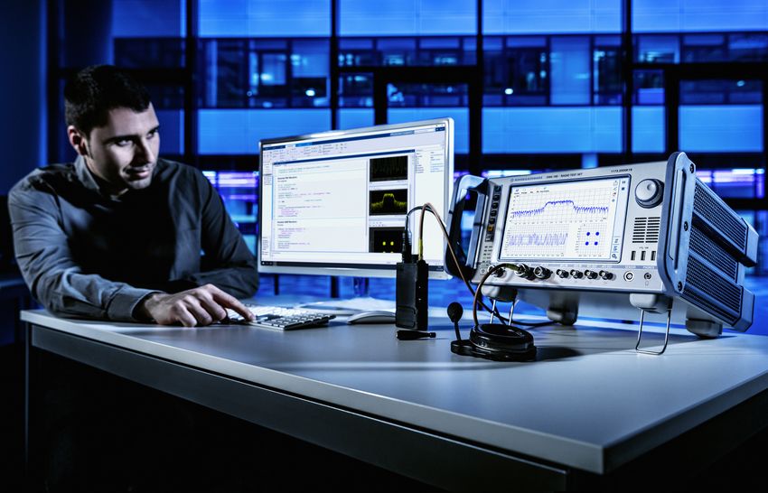
The R&S®CMA180 with a DUT.
2
KEY FACTS
► Frequency range from 100 kHz to 3 GHz ► Use of R&S®NRP and R&S®NRT power sensors –
no configuration required
► Analog modulation and demodulation
(CW, AM, FM, PM, SSB) ► I/Q recorder and ARB generator
► Up to 150 W peak input power and up to ► Digital signal analysis of proprietary waveforms
100 W continuous input power
► ILS, VOR and marker beacon generator
► Signal level for receiver measurements
► VoIP in line with EUROCAE ED-137B/C for
can be lowered to –140 dBm
ATC radios
► Integrated audio generators
► Digital receiver and transmitter measurements
► Audio quality tests (SINAD, THD, SNR) (DMR, APCO P25, dPMR, NXDN, TETRA)
► Integrated sweeping spectrum analyzer, ► POCSAG and Zigbee receiver measurements
tracking generator and oscilloscope
BENEFITS
All-purpose device Testing multimode radios
► page 4 ► page 14
Accurate and flexible High-performance extension
► page 6 ► page 15
Extensive measurement functionality Test features for special applications
► page 8 ► page 16
Convenient operation Test automation with R&S®CMArun software
► page 12 ► page 20
Digital receiver and transmitter measurements Wide range of options and add‑ons
► page 13 ► page 22
Rohde & Schwarz R&S®CMA180 Radio Test Set 3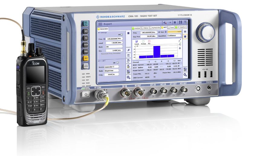
ALL-PURPOSE DEVICE
Diverse, future-ready configuration options Mobility
The R&S®CMA180 has a frequency range from 100 kHz to The R&S®CMA180 can be equipped with an AC power
3 GHz, making it ideal for testing all common analog radio supply for operation at 110 V to 250 V or a DC power
systems. Input levels up to 150 W are no problem for the supply for operation at 10 V to 30 V. Equipped with a DC
test set. The flexible internal switching capabilities for the power supply, the R&S®CMA180 can also be powered via
audio and RF paths make the R&S®CMA180 suitable for a a vehicle's power supply. The DC power supply can be
wide range of test requirements. connected to an external AC/DC converter for AC opera‑
tion at 110 V to 250 V.
Users can configure the internal generators, external audio
sources, filters and measurements depending on the An optional battery pack ensures maximum mobility and
application. In the predefined test scenarios for receiver, turns the R&S®CMA180 with DC power supply into a
transmitter and duplex tests, the RF and audio paths are portable tester that can be brought directly to the DUT.
preconfigured. This saves time and eliminates configura‑ Equipped with the battery pack, the portable, multifunc‑
tion errors for standard test cases. If the R&S®CMA180 is tional radio test set is ideal for measurements in vehicles
to be used for applications other than these standard test and aircrafts.
configurations, the expert mode allows users to access all
configuration options. An optional display protective cover that can be easily
attached to the front of the instrument reliably protects the
R&S®CMA180 display and front panel.
The display protective cover protects the
R&S®CMA180 for mobile applications.
4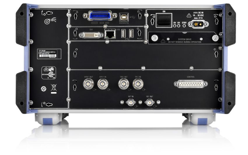
Applications in the R&S®CMA180 frequency range
30 MHz 300 MHz 3000 MHz
VHF UHF
30 145 443 868 2400 MHz
The R&S®CMA180 with optional
battery pack for mobile applications.
Rohde & Schwarz R&S®CMA180 Radio Test Set 5
ACCURATE AND FLEXIBLE
Top RF performance for transmitter and receiver tests Many different connectivity options
For RF transmitter tests, all relevant parameters are The R&S®CMA180 offers many connectivity options that
measured, including transmit power, transmit frequency, make it possible to realize almost any type of application.
frequency error and modulation parameters. The trans‑ For computer accessories such as a mouse and keyboard,
mit power can be as high as 150 W. A spectrum analyzer there are USB ports on the front and rear panels. The front
is available for examining the signals in the frequency panel includes two additional analog audio outputs, two
domain. Harmonics and the adjacent channel power can audio inputs and three RF connectors.
also be measured.
The R&S®CMA180 can be integrated into a LAN via the
To investigate the receiver's sensitivity, RF signals are Gigabit Ethernet port on the rear panel, providing a con‑
generated at very low powers. The signal power can be venient way to perform software updates over the net‑
reduced to as low as –140 dBm. To analyze the audio sig‑ work. The R&S®CMA180 can also be remote controlled.
nal, the audio signal demodulated by the DUT can be Trigger, clock, SPDIF, TTL inputs/outputs and relay ports
played back to the R&S®CMA180 via BNC or SPDIF. are located on the rear panel.
External connection via relays and TTL inputs/outputs.
6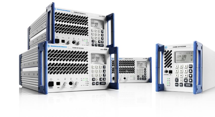
Switching and controlling external equipment
The rear panel includes a D-Sub connector for controlling
external equipment or DUTs. Two relays, four TTL outputs
and four switchable TTL inputs/outputs are available.
Remote control commands can be used to address and
evaluate relays and TTL inputs/outputs in order to switch
instruments or query their status. The R&S®CMA180 per‑
forms both measurement and control tasks. Proprietary
interfaces can also be addressed. These features make the
R&S®CMA180 a key element in any radiocommunications
test system.
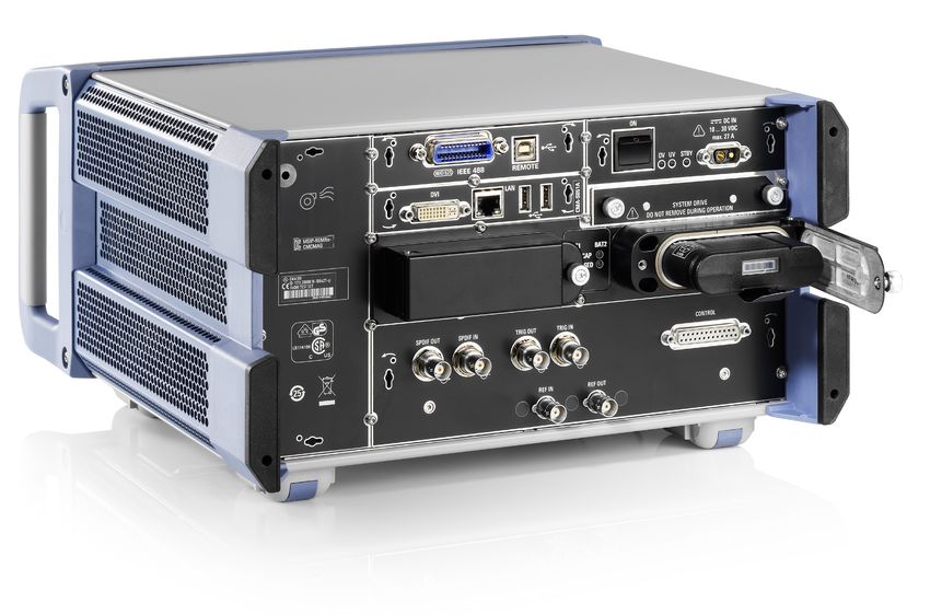
Rear view of the R&S®CMA180.
Rohde & Schwarz R&S®CMA180 Radio Test Set 7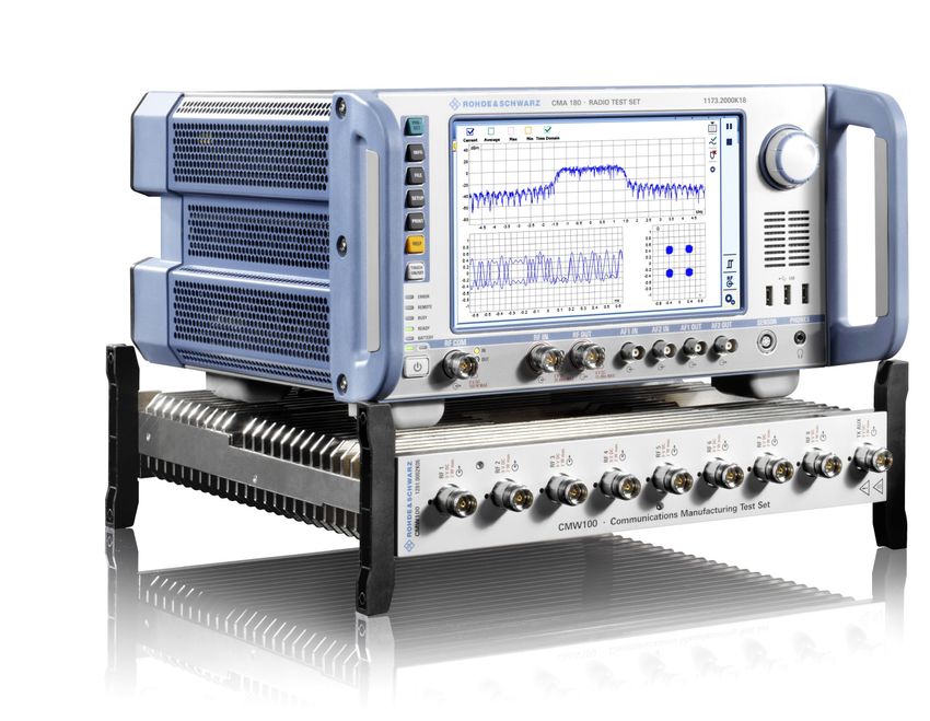
EXTENSIVE MEASUREMENT
FUNCTIONALITY
Analog modulation and demodulation
The R&S®CMA180 supports CW, AM, FM, PM and SSB
modulation and demodulation methods. For receiver mea‑
surements, external signals that are fed in via the analog
or digital audio inputs, as well as internally generated sig‑
nals and audio files, can be modulated onto an RF carrier.
For transmitter measurements, the transmitter signals are
demodulated and analyzed. The spectrum analyzer is used
to display demodulated audio signals. Depending on the
type of modulation, either the modulation deviation or
modulation depth is measured and displayed. For receiver
Working with DCS. tests, the RF generator can produce signaling tones and
bit sequences in addition to the wanted signal. The user
has access to a CTCSS and configurable subaudio tones.
DTMF, five-tone sequences and the digital CDS technique
are all supported.
The test set also provides the necessary measurements to
analyze the frequency, duration, frequency deviation and
bit errors of the generated signals.
Audio generators
The R&S®CMA180 is equipped with four internal audio
generators that can generate two tones simultaneously
and modulate them onto the RF carrier. Depending on the
generator used, the signal is available to the internal RF
modulator or at the audio ports. If the signal is generated
for an external application, the user has a choice of analog
The multitone generator offers versatile settings. or digital output (SPDIF). The levels can be set as required.
If the signal is to be modulated onto the RF carrier, the
modulation characteristics can be configured.
Multitone
In addition to single sine tones, the audio generators can
generate up to 20 tones simultaneously that can be fed to
the AF connectors or used as a modulation source for FM,
AM, PM and SSB. The frequency and level of each tone
can be tuned individually.
Two tone
Two-tone measurements such as SSB linearity
measurements can be performed using the two-tone
measurement function.
The multitone generator generates up to 20 tones.
8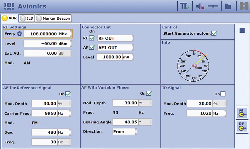
Audio quality tests                                           FFT spectrum application
All audio signals – both externally fed signals and demodu‑   The integrated FFT spectrum application is used to
lated audio signals – can be analyzed. Highpass, lowpass      observe the test signal in the frequency domain. Users can
and weighting filters can be applied to the audio signals.    set markers and insert minimum, maximum and average
The quality of the audio signal is determined with SINAD,     curves. Both the span and the assessment bandwidths are
SNR and THD. Users can select any frequency to be the         configurable. In the zero span mode, triggers help users
test frequency. SINAD, SNR and THD are determined             optimally display and investigate transients. The transient
and displayed simultaneously. There is no need to switch      signals to be analyzed can be broken down into I and Q
between SNR and SINAD measurements. The spectrum              components and displayed graphically, significantly simpli‑
analyzer is used to examine the signals in the frequency      fying analysis of radio transients.
domain.

Automatic measurement routines
The R&S®CMA180 can automatically perform measure‑
ments that normally require extensive manual setup. It
provides automatic measurement routines for
► TX modulation sensitivity
► RX sensitivity
► RX squelch
► RX IF bandwidth

During the RX sensitivity measurement, for example,
the RF level is reduced until a predefined SINAD value is
reached. The measurement then ends and the RF level is
displayed as the measured value.

Detailed analysis of audio quality.                           I/Q view of FFT spectrum.

                                                                                          Rohde & Schwarz R&S®CMA180 Radio Test Set 9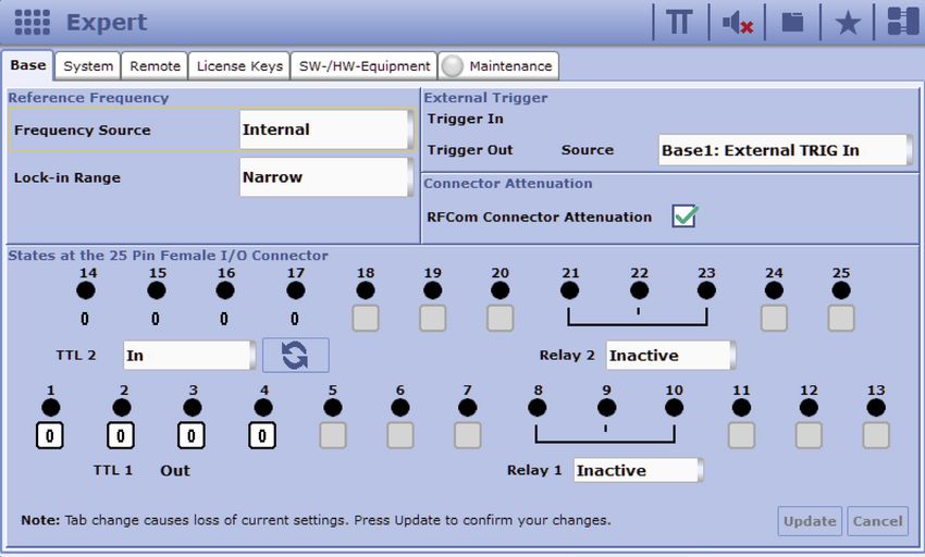
Adjacent channel power (ACP) and occupied bandwidth
The ACP measurement determines the power that a trans‑
mitter emits into adjacent channels. This key measurement
for channel based radiocommunications helps to mini‑
mize interference in adjacent channels. Channel and mea‑
surement bandwidth settings can be adjusted as needed.
Results are presented in graphical and tabular form. The
occupied bandwidth can be measured to determine the
bandwidths occupied by an adjustable percentage of the
power.
Oscilloscope
Adjacent channel power measurement with adjustable channel and The integrated oscilloscope shows the audio signals
measurement bandwidths. that are fed into the audio ports, including the demodu‑
lated audio signals for transmitter tests. Marker functions
simplify analysis of these audio signals. Audio signals can
be viewed in both the time domain and in the frequency
domain thanks to FFT, allowing easy and comprehensive
analysis of all audio signals.
Built-in sweeping spectrum analyzer with time domain
analysis (zero span)
The R&S®CMA180 features a built-in sweeping spec‑
trum analyzer. Extensive configuration options make this
analyzer a universal tool for testing all types of DUTs. The
spectrum analyzer has two operating modes: full span and
user-defined spans. The zero span mode enables analysis
in the time domain. In combination with the triggers, it is
possible, for instance, to display transients.
Audio signal analysis with built-in oscilloscope.
Burst signals can also be analyzed in the spectrum ana‑
lyzer's time domain. Depending on the sweep time set‑
ting, the video trigger allows users to display one or
more bursts. The burst duration is determined in the time
domain view.
The signal edges of burst signals can also be analyzed.
Using the video trigger and the configurable trigger off‑
set, acquisition begins with the rising edge. By setting the
sweep time accordingly, it is possible to display exactly
one burst. Setting markers makes signal analysis easier
and quickly delivers precise measurement results.
Highpass filter measurement with the built-in tracking generator.
10Intermodulation with integrated interfering signal
Inter. Inter.
(FM) (CW)
f
Interference Δf Δf
> 65 dB
Signal
Δf: 1 MHz to 10 MHz
Frequency m
odulation with an integrated
interfering signal.
The spectrum analyzer's max function is used to examine measure co-channel rejection and adjacent channel sup‑
the hopping range when analyzing hopping radio systems. pression, eliminating the need to employ an additional
Even when the hopping sequence is unknown, it is generator to generate the interfering signal.
possible to gain information about the frequency range.
Gaps indicate unused frequencies. Each burst can also be The R&S®CMA180 simplifies intermodulation measure‑
analyzed in the time domain. ments since the user can generate the two RF signals at
different levels within the available 20 MHz bandwidth.
Tracking generator Both signals – the wanted signal and the interferer – can
The built-in tracking generator makes it easy to deter‑ be modulated independently of one another. The levels
mine the frequency response of passive and active RF of the two signals can also be set independently of one
components. With an external VSWR bridge, the track‑ another. No additional equipment is needed to perform
ing generator can also be used for VSWR measurements. complex measurements.
This extends the range of applications to include antenna
measurements. Location services – GPS, Galileo, GLONASS, Beidu
Many of today's radios have GPS, Galileo, GLONASS or
Built-in interferer Beidu receivers. These can be easily tested using the
The R&S®CMA180 can generate two RF signals. If these R&S®CMA180. The test set outputs a position signal that
signals are positioned outside of the DUT's receive win‑ is received and analyzed by the DUT. The position on the
dow in such a way that at least one intermodulation prod‑ DUT can then be compared to the position sent by the
uct lies within the receive window, it is possible to assess R&S®CMA180.
the receiver quality. The built-in interferer allows users to
Rohde & Schwarz R&S®CMA180 Radio Test Set 11CONVENIENT OPERATION
Advanced touchscreen plus rotary knob Various ways of displaying parameters and measurement
Users can operate the R&S®CMA180 completely via results
the touchscreen. All functions can be quickly accessed. Users have a choice of two modes for displaying param‑
Measurement results are clearly and conveniently dis‑ eters and measurement results. The tab mode is best for
played. Users can also use the rotary knob to change set‑ displaying the values in detail. All generator and analyzer
tings, an especially useful feature that allows them to values are displayed in separate full-screen tabs.
scroll through the frequencies and levels and immediately
see the impact on the measurement results. The split-screen mode offers a complete overview, where
the generator and analyzer values are displayed simultane‑
Predefined test scenarios for minimal configuration effort or ously. Generator settings are changed on the left side of
expert mode for maximum freedom the screen and the results are instantly displayed on the
Predefined scenarios for standard measurement tasks right side. The operating controls for the spectrum ana‑
enable users to configure the R&S®CMA180 software and lyzer can be hidden, and the results displayed across the
hardware with a finger tap. Predefined scenarios are pro‑ entire screen for optimum viewing.
vided for TX measurements, RF measurements, spec‑
trum analysis, etc. In expert mode, users can configure Special trim view
the R&S®CMA180 as required. Audio and RF paths can The trim view graphically displays selected measurement
be switched as needed. All generators and analyzers values and their limits. In contrast to scalar displays, this
are accessible and configurable. In this mode, the view makes it easier to recognize when the values fall
R&S®CMA180 can perform tasks that go far beyond stan‑ below or exceed limits and facilitates comparison of trans‑
dard analog measurements. mitters and receivers.
Remote control for easy integration into automated test
environments via LAN or GPIB
When remotely controlled via Ethernet or an optional GPIB
Select predefined test scenarios or switch to expert mode. interface, the R&S®CMA180 can be seamlessly integrated
into automated test environments and used for round-the-
clock testing.
Clearly organized touchscreen. Special trim view.
12DIGITAL RECEIVER AND
TRANSMITTER MEASUREMENTS
Digital receiver measurements This allows the R&S®CMA180 to analyze a wide range of
The R&S®CMA180 can generate test signals for digital digital signals. The user simply selects the standard to be
radio standards. Signal content can be configured to tested, and the test set automatically sets the required
match test requirements. Signals can carry audio test analyzer parameters. The R&S®CMA180 supports DMR,
tones or pseudo random bit sequences (PRBS), for dPMR, NXDN, APCO P25, TETRA and LTE. Digital and
example. Signaling parameters such as DMR color analog measurements are started at the push of a button.
code can be configured on the instrument's intuitive Results are displayed in an overview and in detailed graphs
GUI, making it easy to perform receiver tests for digital and diagrams.
standards such as DMR, NXDN, APCO P25 and dPMR.
Custom mode
The digital signal generator can be used for testing digital In custom mode, users can define and measure their own
communications systems, and also supports POCSAG signals. Signals are defined with the signal analyzer. The
and Zigbee. For TETRA and LTE, signals generated with R&S®CMA180 then tests the signals. This is particularly
the R&S®WinIQSIM2™ simulation software can be played important in the case of tactical radios, where the wave‑
back. form is often classified.
Digital transmitter measurements
The integrated vector signal analyzer demodulates digital
signals and delivers results, including eye diagrams,
symbol distribution and scalar values such as frequency
deviation and EVM.
Digital signal generator for receiver tests (left) and overview of digital measurements (right).
Rohde & Schwarz R&S®CMA180 Radio Test Set 13TESTING MULTIMODE RADIOS
Modern public safety radios support LTE, Wi-Fi and LTE transmitter measurement
Bluetooth® in addition to the classic trunked radio stan‑ The R&S®CMA180 uses an integrated vector signal ana‑
dards, e.g. TETRA, APCO and DMR. This means that the lyzer to measure transmitters. This signal analyzer is set up
scope of tests also needs to include these technologies. for LTE by selecting the required standard and is then con‑
The R&S®CMA180 supports the measurement of classic figured automatically. If the LTE test object is set to trans‑
analog and digital radio signals through to LTE. mit mode, the R&S®CMA180 displays the measured power
and EVM values. Other measurement images such as the
constellation diagram are also shown.
LTE receiver measurement
The LTE receivers are measured using the ARB generator.
This generator supports LTE waveforms that can be gener‑
ated with R&S®WinIQSIM2™ or MATLAB®, for example.
The LTE receiver can evaluate these signals and thus deter‑
mine the sensitivity.
The Bluetooth® word mark and logos are registered trademarks owned by
Bluetooth SIG, Inc. and any use of such marks by Rohde & Schwarz is under license.
LTE transmitter measurement.
14HIGH-PERFORMANCE EXTENSION
With its frequency range of 100 kHz to 3 GHz and mea‑ Frequency range and bandwidth extension
surement bandwidth of 20 MHz, the R&S®CMA180 covers Waveforms that operate at a bandwidth of up to 160 MHz
all common analog and digital standards. For applications and in a frequency range up to 6 GHz can be measured
that go beyond this, the R&S®CMA180 can be fitted with a using the R&S®CMA‑XRT100 solution. A standalone ARB
high‑performance frontend (R&S®CMA‑XRT100 setup). The generator is available for receiver tests. For the transmitter
instrument has integrated operation and is controlled fully tests, the RF information is sent to the integrated vector
via the R&S®CMA180. signal analyzer, where it is evaluated. The integrated oper‑
ation enables seamless work on the R&S®CMA180 and
R&S®CMA‑XRT100.
Parallel testing with the R&S®CMA-XRT100
Headline Increase in throughput thanks to parallel testing
If multiple radios need to be measured, the parallel test
approach offers an efficient solution: up to eight radios
are connected to the R&S®CMA‑XRT100 at the same time
and measured simultaneously. This saves a considerable
amount of time, particularly in the case of receiver mea‑
surements, as they take much longer than the transmitter
tests.
R&S®CMA-XRT100 setup.
Rohde & Schwarz R&S®CMA180 Radio Test Set 15TEST FEATURES FOR SPECIAL
APPLICATIONS
Avionics generator for ILS, VOR and marker beacon signals Both a glide slope and localizer are available for ILSs. The
The outstanding signal quality of the R&S®CMA180 makes signal parameters can be modified to meet test require‑
it an extremely versatile radio tester for aircraft. The test ments. DDM, SDM, modulation frequencies, etc., can
set can analyze ILS, VOR and marker beacon signals be set. The settings are displayed on simulated on-board
for aircraft landing systems as well as airborne radio instruments, making it easy to compare target and actual
signals. Equipped with a battery pack and antenna, the values.
R&S®CMA180 is a standalone instrument that is ideal for
aircraft maintenance.
ILS glide slope generator.
Generator settings for ILS localizer.
16Numerous signal parameters are also available for VOR
and marker beacon signals. ID signaling can be activated
for all avionics signals. For avionics signals, the audio
signal can be fed to the audio ports to generate the signal
with an external signal generator.
Configuration of VOR generator.
Marker beacon settings.
Rohde & Schwarz R&S®CMA180 Radio Test Set 17Avionics VoIP generator and analyzer Configuration of the VoIP connection is straightforward
The R&S®CMA180 incorporates a VoIP generator and and intuitive, and the status displays for the connection
analyzer in line with EUROCAE ED-137B/C. The VoIP inter‑ provide an excellent overview. The radio to be tested is
face is fully integrated in the R&S®CMA180, and users connected to the test set via the integrated LAN inter‑
can switch between analog audio and VoIP testing at the face. It is also possible to connect multiple transmitters or
push of a button. This allows easy and extensive testing of receivers via an optional LAN switch that is powered via a
airborne radios via both the VoIP (LAN) interface and the USB cable, meaning that the R&S®CMA180 can be oper‑
analog audio (RF COM) interface. ated independently of the mains supply.
VoIP generator test setup
Radio transmitter
e.g. ¸SU4200
VoIP data
¸CMA180 Transmitter
► Decodes VoIP data
► Modulates RF with audio signal
TX test
RF modulated ► Demodulates RF signal
with audio signal ► Analyzes audio signal quality
VoIP analyzer test setup
Radio receiver
e.g. ¸EU4200C
RF modulated
with audio signal Receiver
¸CMA180 ► Demodulates RF signal
► Encodes audio signal
VoIP data
RX test
► Decodes VoIP data
► Analyzes audio signal quality
18Waveforms (ARB)
In the ARB waveform mode, the R&S®CMA180
processes I/Q data that is available as wave‑
form files, making it possible to generate any
application-specific modulation signals. The
¸WinIQSIM2™ waveform creation tool
allows users to create waveform files directly
and conveniently. I/Q data can also be gener‑
ated using commercial software tools such as
MATLAB®, Mathcad® and ADS®. This data must
then be converted into the waveform file format
using the Rohde& Schwarz Matlab transfer tool‑
box or the Rohde & Schwarz I/Q wizard.
The R&S®WinIQSIM2™ graphical user interface
also makes it possible to very quickly create dig‑
ital waveforms. FSK, PSK and QAM modulated
test signals can be generated and then replayed
using the R&S®CMA180.
GPS, Galileo and GLONASS satellite navi‑
gation signals can also be generated with ARB file generation with R&S®WinIQSIM2™.
R&S®WinIQSIM2™ and then loaded into the
R&S®CMA180 and replayed.
Field to lab
The I/Q recorder makes it possible to record RF
signals via the RF ports. Signals can be recorded
over a wired line or via an antenna thanks to the
wide dynamic range of the R&S®CMA180. The
signals are recorded and stored as I/Q data. The
recorded data can be replayed on the ARB gen‑
erator or analyzed with the R&S®VSE vector sig‑
nal explorer software.
Triggers and settable sample rates turn the I/Q
recorder into a universal tool to simulate real-
life scenarios in the lab or to generate reference
signals.
Recording RF signals for playback in the lab.
Rohde & Schwarz R&S®CMA180 Radio Test Set 19TEST AUTOMATION WITH
R&S®CMArun SOFTWARE
Ready-to-use solution for configuring application R&S®CMArun offers a separate run environment in which
test sequences test sequences are created and executed using a mouse
R&S®CMArun is available for test sequence control. It pro‑ and keyboard. Additionally, an R&S®CMArun component
vides a graphical user interface for programming a test has been integrated into the R&S®CMA180 touchscreen,
sequence. Individual settings and measurement tasks mainly to e
xecute previously created test sequences.
can be configured and arranged in a specific sequence.
Sequences, loops and conditional queries help users eas‑ Extensive function library
ily create and execute complex test sequences. Each set‑ The R&S®CMArun function library contains numerous test
ting and measurement value is logged and then summa‑ functions that range from analog and digital receiver and
rized and stored in a report. For measurements with limit transmitter tests to sensitivity measurements and loading
values, pass or fail indicators can be displayed for each and starting waveforms in the ARB generator.
measurement. The R&S®CMA180 can also be controlled
using VISA drivers and SCPI commands. Control via SNMP, serial interfaces and SCPI
Radios with an SNMP interface can also be controlled by
R&S®CMArun and are handled like DUTs that have a serial
interface. Entire test environments can be automated
since other equipment such as power supplies can also be
R&S®CMArun running on the R&S®CMA180. integrated via SCPI.
Configuration of R&S®CMArun test items. Automatically generated test report from R&S®CMArun.
20Battery life testing
Battery life is crucial for all handheld radios and rescue
beacons. To ensure a specific battery life, the radio's
battery size, components and software must be devised
accordingly.
Battery life measurements allow users to keep an eye on
the radio's current, voltage and power. The R&S®CMA180
provides a detailed overview of the power consumed for
transmission and standby, making it possible to optimize
operations. This application requires the battery life test
(R&S®CMA‑KT061) and R&S®CMArun analog radio tests
(R&S®CMA‑KT051) options.
The R&S®RT‑ZVC04 multi-channel p ower probe.
Battery life testing with R&S®RT-ZVC02/R&S®RT‑ZVC04
multi‑channel power probe
Battery life measurements require monitoring both the Fully automated test solution for R&S®Series4200 radios
current and the voltage over time, as well as calculating A fully automated test solution based on R&S®CMArun is
the instantaneous power at high sampling rates. To meet available for R&S®Series4200 radios with an SNMP inter‑
these requirements, it is necessary to measure the power face and R&S®Series4100 radios with an SNMP or serial
a device consumes based on a real use case, i.e. the interface. The specially developed radio test and remote
device must be powered by a real battery, or via the USB control o ptions (R&S®CMA‑KT420, R&S®CMA‑KT410
interface, or from the mains via an AC/DC power supply. and R&S®CMA‑KT440) together with the radio adapter
(R&S®CMA‑Z421A), which is used to physically con‑
The R&S®RT‑ZVC02 and R&S®RT‑ZVC04 multi-chan‑ nect the radio to the R&S®CMA180, make it possible
nel power probes are designed to cover precisely such to instantly test R&S®Series4200, R&S®Series4100 and
uses cases, offering two (R&S®RT‑ZVC02) and four R&S®Series4400 radios without any hardware modifica‑
(R&S®RT‑ZVC04) voltage channels plus two/four current tions or programming.
channels.
The test plans created in R&S®CMArun can be executed
via a LAN-connected PC or loaded and run directly on the
test set. The latter option is particularly advantageous for
mobile use. The created test reports can be stored on the
R&S®CMA180 or exported via USB or LAN.
The R&S®Series4200 radios.
Rohde & Schwarz R&S®CMA180 Radio Test Set 21WIDE RANGE OF OPTIONS
AND ADD‑ONS
The R&S®CMA180 comes with a wide range of options and add-ons. Below you will find an overview
of the most important products. Our sales engineers will be happy to provide you with details and
answer your questions.
SOFT CASE AND TRANSIT CASE
A soft case and a transit case are available for the
R&S®CMA180. The transit case features wheels and a
foam insert that accommodates the test set and acces‑
sories. It has an integrated pressure equalizing valve, is
waterproof and complies with MIL-STD-810F. The soft
case protects the R&S®CMA180 during transport. The
R&S®CMA180 can be operated from inside the case since
the front panel remains accessible. Air compartments next
to the R&S®CMA180 protect it from overheating. The test
set is portable and instantly ready to use.
Transit case.
Soft case.
R&S®NRP AND R&S®NRT POWER SENSORS
The high-precision R&S®NRP power sensors can
be connected directly to the dedicated sensor
input and used immediately without any addi‑
tional configuration. The R&S®NRT directional
power sensors can also be connected. These
sensors can be used to measure VSWR.
R&S®NRP power sensors. Measurements with R&S®NRT power sensor connected to the R&S®CMA180.
22SHIELD BOX, ANTENNA COUPLER
AND AUDIO ACCESSORIES
The R&S®CMW-Z10 RF shield box together with the
R&S®CMW-Z11 antenna coupler are an excellent com‑
bination for wireless testing of analog radios. The
R&S®CMW-Z10 RF shield box features outstanding char‑
acteristics for protection against ambient emissions. With
its numerous shielded connector feedthroughs, it is ideal
for all types of applications. The R&S®CMW-Z15 audio
measurement option provides a loudspeaker and a micro‑ The R&S®CMW-Z10 RF shield box
phone for the shield box, enabling wireless testing of radio with the R&S®CMW-Z11 antenna
systems including loudspeakers and microphones. coupler and the R&S®CMW-Z15 audio
measurement option.
RADIO TEST SET
The R&S®CTH200A portable radio test set reliably tests
analog FM radio systems under harsh environmental con‑
ditions. Specially designed for outdoor use, it measures
power, frequency, receiver sensitivity and VSWR and helps
find cable faults. This portable radio test set is an ideal tool
for service and maintenance work.
R&S®CTH200A portable
analog radio test set.
HANDLING OF EXTERNAL AUDIO IMPEDANCES
The R&S®CMA180 supports all external audio impedances. The audio ports on the R&S®CMA180 can be adapted
The external circuitry and the impedances of the radio using external BNC feedthroughs with an integrated 600 Ω
under test can be configured in a menu. Individual values impedance (R&S®CMA-Z651A). The settings and configu‑
can be set for each audio input and output. rations made are taken into account in the measurements.
Configuring external
audio impedances.
Rohde & Schwarz R&S®CMA180 Radio Test Set 23SPECIFICATIONS IN BRIEF
Specifications in brief
RF frequency range 0.1 MHz to 3000 MHz
Output level range RF generator up to +16 dBm (max.)
Maximum allowed input power RF input up to 150 W
Modulation CW, AM, FM, PM, SSB
Arbitrary waveform generator (ARB) R&S®CMA-B110D RF bandwidth up to 20 MHz
R&S®CMA-B110D 4 Gbyte memory
Spectrum analyzer R&S®CMA-K120 0.1 MHz to 3000 MHz
FFT spectrum analyzer span 10 kHz to 20 MHz
analog inputs/outputs, SPDIF,
Audio signals
internal AF generators/analyzers
Power supply AC 100 V to 240 V
DC 10 V to 30 V or battery
85 W
RF, AF, LAN, USB, DVI, Rohde & Schwarz power
meters, reference frequency in/out,
Connectivity
trigger in/out, TTL in/out,
GPIB (R&S®CMA-B612A)
¾ 19", 4 RU,
Dimensions W×H×D 360.5 mm × 195.4 mm × 351 mm
(14.2 in × 7.7 in × 13.8 in)
Weight fully equipped 13 kg (28.7 lb)
base unit without options 10.9 kg (24 lb)
R&S®CMA180 ports
Connector Type Position Use
mouse, keyboard, USB flash drive for software
3 × USB USB port, type A front
updates and screenshots
power measurement with high-precision
1 × power sensor Rohde & Schwarz sensor front
R&S®NRP/R&S®NRT power sensors
2 × audio in BNC front analog audio, e.g. receiver measurements
2 × audio out BNC front analog audio, e.g. transmitter measurements
1 × bidirectional RF N female front standard RF port for the DUT
1 × RF out N female front RF port for high output power
1 × RF in N female front sensitive RF input
mouse, keyboard, USB flash drive for software
2 × USB 3.0 USB port, type A rear
updates and screenshots
integration into a network, e.g. for software
1 × Gigabit LAN RJ-45 port rear updates; remote control of the R&S®CMA180;
remote desktop operation
1 × SPDIF in BNC rear digital audio, e.g. receiver measurements
1 × SPDIF out BNC rear digital audio, e.g. transmitter measurements
1 × trigger in BNC rear for external triggers
1 × trigger out BNC rear trigger for external equipment
1 × parallel port D-Sub rear TTL in/out and relays for custom applications
24ORDERING INFORMATION
Designation Type Order No.
Base unit
Radio test set R&S®CMA180 1173.2000K18
Selections
Solid-state disk R&S®CMA-S052P 1173.5100.14
AC power supply R&S®CMA-S054B 1173.5151.03
DC power supply R&S®CMA-S054M 1173.5151.14
Options and extras
Hardware options
Baseband generator, 4 Gbyte memory R&S®CMA-B110D 1173.5751.05
IEC/IEEE bus interface R&S®CMA-B612A 1173.5800.02
OCXO reference oscillator R&S®CMA-B690A 1173.5851.02
OCXO reference oscillator, high-performance R&S®CMA-B690M 1173.5851.14
Battery compartment R&S®CMA-B060A 1209.5003.02
Software options, general purpose
Signal analyzer (SA), tracking generator (TG), oscilloscope (scope) R&S®CMA-K120 1173.6206.02
ILS/VOR generator R&S®CMA-K130 1209.5703.02
I/Q recorder R&S®CMA-K220 1209.6200.02
VoIP support in line with ED-137B/C R&S®CMA-K610 1209.7058.02
Software options, R&S®CMArun
Analog radio tests R&S®CMA-KT051 1209.5603.02
Analog radio tests, advanced R&S®CMA-KT052 1209.7412.02
Battery life test R&S®CMA-KT061 1209.6300.02
VOR/ILS tests R&S®CMA-KT130 1209.7393.02
Digital tests (DMR/APCO/NXDN) R&S®CMA-KT200 1209.8619.02
R&S®Series4100 radio test R&S®CMA-KT410 1209.7764.02
R&S®Series4200 radio test R&S®CMA-KT420 1209.6422.02
R&S®Series4400 radio test R&S®CMA-KT440 1209.7358.02
VoIP support R&S®CMA-KT610 1209.7335.02
Software options, waveforms
Waveform library, GPS tests R&S®CMA-KV140 1209.5855.02
Waveform library, GLONASS tests R&S®CMA-KV141 1209.7206.02
Waveform library, Galileo tests R&S®CMA-KV142 1209.7229.02
Waveform library, Beidou tests R&S®CMA-KV143 1209.7241.02
Waveform library, APCO fading tests R&S®CMA-KV240 1209.7087.02
Software options, waveforms, with R&S®WinIQSIM2™
LTE tests R&S®CMA-KW500 1209.8677.02
Bluetooth® tests R&S®CMA-KW610 1209.8925.02
GPS tests R&S®CMA-KW620 1209.6222.02
GLONASS tests R&S®CMA-KW621 1209.6245.02
Galileo tests R&S®CMA-KW622 1209.6268.02
WLAN tests R&S®CMA-KW656 1209.8919.02
TETRA Rel. 2 tests R&S®CMA-KW668 1209.6874.02
Software options, digital
Signal analyzer, base R&S®CMA-K300 1209.8990.02
Signal analyzer, digital (APCO, DMR, NXDN, dPMR, TETRA) R&S®CMA-K305 1209.9009.02
Signal analyzer, LTE FDD R&S®CMA-K320 1209.8877.02
POCSAG generator R&S®CMA-KG260 1209.7487.02
Zigbee generator R&S®CMA-KG250 1209.7506.02
FSK generator R&S®CMA-K210 1209.8654.02
Rohde & Schwarz R&S®CMA180 Radio Test Set 25Designation Type Order No.
MMI
MMI language Russian R&S®CMA-KL007 1209.6468.02
MMI language French R&S®CMA-KL033 1209.6480.02
MMI language Chinese R&S®CMA-KL086 1209.6500.02
Extras
Transit case R&S®CMA-Z020A 1209.5555.02
Soft case R&S®CMA-Z025A 1209.5510.02
Display protective cover R&S®CMA-Z030A 1209.9796.00
External power supply R&S®CMA-Z053A 1173.6058K00
Protective caps R&S®CMA-Z059 1209.6445.02
Lithium-ion battery pack (two batteries) R&S®CMA-Z061A 1209.5303.02
Lithium-ion battery charger R&S®CMA-Z062A 1209.5355K02
Radio adapter (box and cables) for R&S®Series4100, R&S®Series4200,
R&S®CMA-Z421A 1209.6522.02
R&S®Series4400 and R&S®Series5200 radios
AF impedance matching unit R&S®CMA-Z600A 1173.6406.02
VoIP kit, ED-137 R&S®CMA-Z610A 1209.7293.02
Feedthrough termination, BNC, 600 Ω (2 × parallel) R&S®CMA-Z650A 1209.6700.02
Feedthrough, BNC, 600 Ω (1 × serial, 1 × parallel) R&S®CMA-Z651A 1209.7170.02
DC block, N type, 10 MHz to 6 GHz R&S®CMA-Z670A 1209.6780.02
Antenna set R&S®CMA-Z680A 1209.6745.02
Accredited calibration (DKD) R&S®CMA-ACA 1209.6368.02
26Designation Type Order No.
Recommended extras
19" rack adapter, 4 RU, ¾, T350 R&S®ZZA-KN10 1175.3091.00
R&S®NRPxxx, Please contact your local
Power sensors
R&S®NRT-Z14/-Z44 Rohde & Schwarz sales office.
Please contact your local
Directional power sensors R&S®FSH-Z14/-Z44
Rohde & Schwarz sales office.
RF shield box R&S®CMW-Z10 1204.7008.02
Antenna coupler, up to 6 GHz R&S®CMW-Z11 1204.7108.02
Audio accessory R&S®CMW-Z15 1204.7508.02
RF cable, up to 6 GHz, N to N R&S®CMW-Z110 1204.7608.02
1073.8495.xx
Attenuator, 3/6/10/20/30 dB, 100 W, 50 Ω R&S®RBU100
(xx = 03/06/10/20/30)
50 W load R&S®CTH-Z30 1207.1700.02
Handset R&S®CMW-Z50 1208.7602.02
Headphones – 0708.9010.00
XLR/BNC adapter set m/f R&S®UP-Z1MF 1411.3306.02
IEC/IEEE bus cable, length: 1 m R&S®PCK 0292.2013.10
IEC/IEEE bus cable, length: 2 m R&S®PCK 0292.2013.20
Supplementary products
Radio test set
Portable radio test set for analog transceivers, including
R&S®CTH200A 1207.1000.02
OTA m easurements and cable fault finder, with operating manual
Accessories for the R&S®CTH200A
Transit case for portable radio test set and accessories R&S®CTH-Z20 1207.1900.02
50 Ω load, BNC adapter and cables R&S®CTH-Z30 1207.1700.02
Multi-channel power probes
Multi-channel power probe with autoranging,
R&S®RT-ZVC02A 1326.0259.32
2 × voltage and 2 × current channels
Multi-channel power probe with autoranging,
R&S®RT-ZVC04A 1326.0259.34
4 × voltage and 4 × current channels
Accessories for multi-channel power probes
Extended cable set, PCB, length: 32 cm R&S®RT-ZA30 1333.1686.02
Extended cable set, 4 mm, length: 32 cm R&S®RT-ZA31 1333.1692.02
Extended cable set, 4 mm, length: 100 cm R&S®RT-ZA34 1333.1892.02
Extended cable set, PCB, length: 100 cm R&S®RT-ZA35 1333.1905.02
Solder-in cable set R&S®RT-ZA36 1333.1911.02
Service options
Extended warranty, one year R&S®WE1
Extended warranty, two years R&S®WE2
Extended warranty, three years R&S®WE3
Extended warranty, four years R&S®WE4
Extended warranty, nine years R&S®WE9
Extended warranty with calibration coverage, one year R&S®CW1
Please contact your local
Extended warranty with calibration coverage, two years R&S®CW2
Rohde & Schwarz sales office.
Extended warranty with calibration coverage, three years R&S®CW3
Extended warranty with calibration coverage, four years R&S®CW4
Extended warranty with accredited calibration coverage, one year R&S®AW1
Extended warranty with accredited calibration coverage, two years R&S®AW2
Extended warranty with accredited calibration coverage, three years R&S®AW3
Extended warranty with accredited calibration coverage, four years R&S®AW4
Your local Rohde & Schwarz expert will help you determine the optimum solution for your requirements.
To find your nearest Rohde & Schwarz representative, visit www.sales.rohde-schwarz.com
Rohde & Schwarz R&S®CMA180 Radio Test Set 27Rohde & Schwarz
Service that adds value The Rohde & Schwarz electronics group offers innovative
► Worldwide solutions in the following business fields: test and mea‑
► Local and personalized surement, broadcast and media, secure communications,
► Customized and flexible cybersecurity, monitoring and network testing. Founded
► Uncompromising quality
► Long-term dependability more than 80 years ago, the independent company which
is headquartered in Munich, Germany, has an extensive
sales and service network with locations in more than
70 countries.
www.rohde-schwarz.com
Sustainable product design
► Environmental compatibility and eco-footprint
► Energy efficiency and low emissions
► Longevity and optimized total cost of ownership
Certified Quality Management Certified Environmental Management
ISO 9001 ISO 14001
Rohde & Schwarz training
www.training.rohde-schwarz.com
Rohde & Schwarz customer support
www.rohde-schwarz.com/support
3606940412
3606.9404.12 05.00 PDP/PDW 1 en
R&S® is a registered trademark of Rohde & Schwarz GmbH & Co. KG
Trade names are trademarks of the owners
PD 3606.9404.12 | Version 05.00 | March 2021 (ch)
R&S®CMA180 Radio Test Set
Data without tolerance limits is not binding | Subject to change
© 2014 - 2021 Rohde & Schwarz GmbH & Co. KG | 81671 Munich, GermanyYou can also read