FUZE PENDANT user manual - Elation EU
←
→
Page content transcription
If your browser does not render page correctly, please read the page content below
FUZE PENDANT™
  user manual
©2021 ELATION PROFESSIONAL all rights reserved. Information, specifications, diagrams,
images, and instructions herein are subject to change without notice. ELATION PROFESSIONAL
logo and identifying product names and numbers herein are trademarks of ELATION
PROFESSIONAL. Copyright protection claimed includes all forms and matters of copyrightable
materials and information now allowed by statutory or judicial law or hereinafter granted. Product
names used in this document may be trademarks or registered trademarks of their respective
companies and are hereby acknowledged. All non-ELATION brands and product names are
trademarks or registered trademarks of their respective companies.

ELATION PROFESSIONAL and all affiliated companies hereby disclaim any and all liabilities for
property, equipment, building, and electrical damages, injuries to any persons, and direct or indirect
economic loss associated with the use or reliance of any information contained within this
document, and/or as a result of the improper, unsafe, insufficient and negligent assembly,
installation, rigging, and operation of this product.

Elation Professional USA | 6122 S. Eastern Ave. | Los Angeles, CA. 90040
323-582-3322 | 323-832-9142 fax | www.elationlighting.com | info@elationlighting.com
Elation Professional B.V. | Junostraat 2 | 6468 EW Kerkrade, The Netherlands
+31 45 546 85 66 | +31 45 546 85 96 fax | www.elationlighting.eu | info@elationlighting.eu
Elation Professional Mexico | AV Santa Ana 30 | Parque Industrial Lerma, Lerma, Mexico 52000
+52 (728) 282-7070

DOCUMENT                   VERSION
              Due to additional product enhancements, an updated version of this document may
              be available online. Please scan the QR Code with your mobile device or visit
              www.elationlighting.com for the latest revision/update of this manual before
              installation and/or programming.

               Document    Software                  DMX
     Date                                                                                         Notes
                Version    Version ≥             Channel Modes
                                         Dimmer1CH, Dimmer Color 4CH, RGBWL
   01/16/20       1.0        1.01H      5CH, RGBWL 16bit 10CH, Standard 10CH,     Preliminary release.
                                       Extended 17CH, HSI 4CH, HSI Extended 9CH
                                                                                  Updated overview and system
   02/25/20       1.1        1.03                  NO CHANGE
                                                                                  menu.
   04/06/20       1.2         NC                   NO CHANGE                      Updated Optional Accessories.
   06/16/20       1.3        1.04                  NO CHANGE                      Updated System Menu.
   08/24/20       1.4        1.06                  NO CHANGE                      Updated primary/secondary
                                                                                  Updated dimensional drawings,
   09/24/20       1.5         NC                   NO CHANGE                      specifications, accessory installation.

   11/04/20       1.6         NC                   NO CHANGE                      Corrected error in DMX Ch. Functions.

   03/09/21       1.7         NC                   NO CHANGE                      Updated Specifications.

                                                         2
CONTENTS

     General Information                          4

     Warranty Returns (USA Only)                  5

     Safety Guidelines                            6

     Maintenance Guidelines                       8

     Overview                                     9

     Optional Accessory Installation Guidelines   11

     Fixture Installation Guidelines              18

     E-FLY Wireless Set Up Guidelines             20

     System Menu                                  21

     Dimmer Modes                                 26

     DMX Channel Functions                        27

     Color Temperature Table                      36

     Virtual Gel Swatch Book Table                37

     Error Codes                                  38

     Specifications                               39

     Dimensional Drawings                         40

     Optional Accessories | FCC Statement         45

                                   3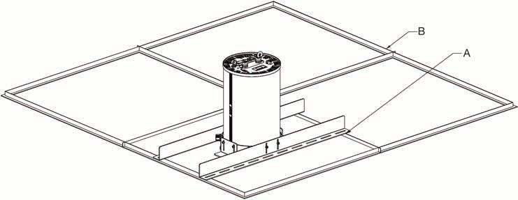
G E N E R A L I N F O R M AT I O N
INTRODUCTION
Please read and understand the instructions in this manual carefully and thoroughly before
attempting to operate this fixture. These instructions contain important safety and use information.

UNPACKING
Every fixture has been thoroughly tested and has been shipped in perfect operating condition.
Carefully check the shipping carton for damage that may have occurred during shipping. If the
carton is damaged, carefully inspect the fixture for damage, and be sure all accessories necessary
to install and operate the fixture have arrived intact. In the event damage has been found or parts are
missing, please contact our customer support team for further instructions. Please do not return this
fixture to your dealer without first contacting customer support. Please do not discard the shipping
carton in the trash. Please recycle whenever possible.

BOX CONTENTS
45° Lens
Pendant Bracket Kit
Locking IP65 Power Cable

CUSTOMER SUPPORT
Contact ELATION Service for any product related service and support needs.
Also visit forums.elationlighting.com with questions, comments or suggestions.
ELATION SERVICE USA - Monday - Friday 8:00am to 4:30pm PST
323-582-3322 | Fax 323-832-9142 | support@elationlighting.com

ELATION SERVICE EUROPE - Monday - Friday 08:30 to 17:00 CET
+31 45 546 85 63 | Fax +31 45 546 85 96 | support@elationlighting.eu

REPLACEMENT PARTS please visit parts.elationlighting.com

        I M P O R T A N T                  N O T I C E !
THERE ARE NO USER SERVICEABLE PARTS INSIDE THIS UNIT.
DO NOT ATTEMPT ANY REPAIRS YOURSELF; DOING SO WILL VOID YOUR
MANUFACTURER’S WARRANTY. DAMAGES RESULTING FROM MODIFICATIONS
TO THIS FIXTURE AND/OR THE DISREGARD OF SAFETY INSTRUCTIONS AND
GUIDELINES IN THIS MANUAL VOID THE MANUFACTURER’S WARRANTY AND
ARE NOT SUBJECT TO ANY WARRANTY CLAIMS AND/OR REPAIRS.

                                                  4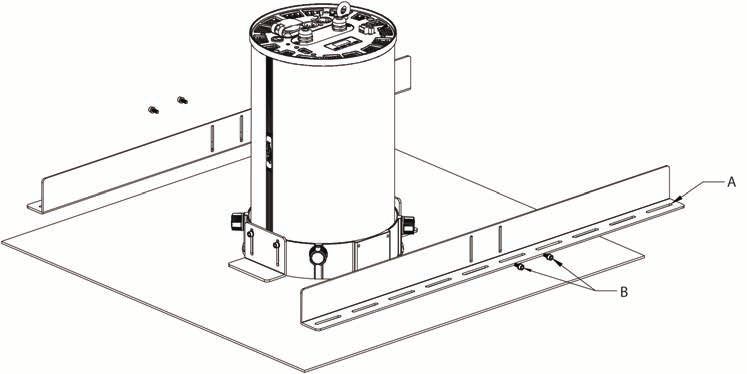
WARRANTY RETURNS (USA ONLY)
To obtain warranty service, a Return Materials Authorization (RMA) number must first be obtained from
ELATION. It is the Customer’s responsibility to provide product proof of purchase and serial number by
acceptable evidence such as an invoice copy or an approved ELATION Extended Warranty Certificate
(“EWC”) and any relevant maintenance records at the time warranty service is sought. Failure to provide
acceptable evidence of product proof of purchase or EWC and any relevant maintenance records may
be cause for denial of warranty service.

Products returned for warranty service must be sent without any accessories (i.e., power, data, and
safety cables, brackets, clamps, rigging hardware, frost filters, gel frames, barn doors, lens, hoses,
nozzles, rack mounting hardware, etc.), must be boxed using the original and/or suitable packaging
materials (double-box and foam) that provides ample product protection for ground and/or air freight
transit, and must be shipped freight pre-paid and insured to ELATION in Los Angeles, CA or an
ELATION Authorized Service Center. The RMA number must be clearly written on the outside of the
return box, and a brief description of the problem and the RMA number must be documented and
included in the box.

Products returned for warranty service without an RMA number clearly marked on the outside of the
package will be refused and returned to the shipper at the Customer’s expense. Products returned for
warranty service, which are received damaged due to inadequate and/or improper packaging and/or
due to damage caused by shipping carrier, may incur additional repair charges before warranty service
begins and/or may void this warranty. If any product accessories (included and/or optional) are shipped
with the product, ELATION and/or the ELATION Authorized Service Center shall have no liability what so
ever for the loss and/or damage to any such accessories, nor the safe return thereof. If the requested
warranty repairs or service (including parts replacement) are within the terms of this warranty, ELATION
will pay return ground transportation shipping charges to a single designated point within the United
States.

                                                    5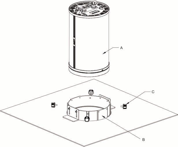
SAFETY GUIDELINES
This fixture is a sophisticated piece of electronic equipment. To guarantee a smooth operation, it is
important to follow all instructions and guidelines in this manual. Elation Professional is not
responsible for injury and/or damages resulting from the misuse of this fixture due to the disregard
of the information printed in this manual. Only qualified and/or certified personnel should perform
installation of this fixture and only the original rigging and mounting hardware included with this
fixture or available optional accessories should be used for installation. Any modifications to the
fixture and/or the included and optional rigging and mounting hardware will void the original
manufacturer’s warranty and increase the risk of damage and/or personal injury.

             PROTECTION CLASS 1 - FIXTURE MUST BE PROPERLY GROUNDED

             THERE ARE NO USER SERVICEABLE PARTS INSIDE THIS UNIT.
             DO NOT ATTEMPT ANY REPAIRS YOURSELF; DOING SO WILL VOID
             YOUR MANUFACTURER’S WARRANTY. DAMAGES RESULTING FROM
             MODIFICATIONS TO THIS FIXTURE AND/OR THE DISREGARD OF
             SAFETY INSTRUCTIONS AND GUIDELINES IN THIS MANUAL VOID THE
             MANUFACTURER’S WARRANTY AND ARE NOT SUBJECT TO ANY
             WARRANTY CLAIMS AND/OR REPAIRS.

             DO NOT PLUG FIXTURE INTO A DIMMER PACK!
             NEVER OPEN THIS FIXTURE WHILE IN USE!
             UNPLUG POWER BEFORE SERVICING FIXTURE!
             NEVER TOUCH FIXTURE DURING OPERATION, AS IT MAY BE HOT!
             KEEP FLAMMABLE MATERIALS AWAY FROM FIXTURE!

             NEVER LOOK DIRECTLY INTO THE LIGHT SOURCE!
             RETINA INJURY RISK - MAY INDUCE BLINDNESS!
             SENSITIVE PERSONS MAY SUFFER AN EPILEPTIC SHOCK!

             INDOOR / DRY LOCATIONS USE ONLY!
             DO NOT EXPOSE FIXTURE TO RAIN AND/OR MOISTURE!

             MINIMUM DISTANCE TO OBJECTS/SURFACES
            M
             IS 1.0 FOOT (0.3 METER)
             MINIMUM DISTANCE OF FLAMMABLE MATERIALS
             FROM THE SURFACE IS 1.6 FEET (0.5 METER)
             MAXIMUM AMBIENT OPERATING TEMPERATURE IS 113°F (45°C)

                                                   6
SAFETY GUIDELINES
DO NOT TOUCH the fixture housing during operation.
DO NOT shake fixture and avoid brute force when installing and/or operating fixture.
DO NOT operate fixture if the power cord is frayed, crimped, damaged and/or if any of the power cord
connectors are damaged or do not fit into the fixture securely with ease.
NEVER force a power cord connector into the fixture. If the power cord or any of its connectors are
damaged, replace it immediately with a new one of similar power rating.
DO NOT block any air ventilation slots. All fan and air inlets must remain clean and never blocked.
Allow approx. 6” (15cm) between fixture and other devices or a wall for proper cooling.
TURN OFF the power and allow approximately 15 minutes for the fixture to cool down before
serving.
ALWAYS disconnect fixture from power before performing any service and/or cleaning procedure.
ONLY handle power cord by the plug end, never pull plug out by tugging the wire portion of the cord.
During the initial operation of this fixture, a light smoke or smell may emit from the interior of the
fixture. This is a normal process and is caused by excess paint in the interior of the casing burning off
from the heat associated with the LED and will decrease gradually over time.
Consistent operational breaks will ensure fixture will function properly for many years.
ONLY use the original packaging and materials to transport the fixture for service.
7MAINTENANCE GUIDELINES
DISCONNECT POWER BEFORE PERFORMING ANY MAINTENANCE!
CLEANING
Frequent cleaning is recommended to ensure proper function, optimized light output, and an
extended life. The frequency of cleaning depends on the environment in which the fixture operates:
damp, smoky or particularly dirty environments can cause greater accumulation of dirt on the
fixture’s optics. Clean periodically with a soft cloth to avoid dirt/debris accumulation.
NEVER use alcohol, solvents, or ammonia-based cleaners.
MAINTENANCE
Regular inspections are recommended to insure proper function and extended life.
There are no user serviceable parts inside this fixture, please refer all other service issues to an
authorized Elation service technician. Should you need any spare parts, please order genuine parts
from an authorized Elation dealer.
Please refer to the following points during routine inspections:
• A detailed electric check by an approved electrical engineer every three months, to make sure the
circuit contacts are in good condition and prevent overheating.
• Be sure all screws and fasteners are securely tightened at all times. Loose screws may fall out during
normal operation resulting in damage or injury as larger parts could fall.
• Check for any deformations on the housing, color lenses, rigging hardware and rigging points
(ceiling, suspension, trussing). Deformations in the housing could allow for dust to enter into the
fixture. Damaged rigging points or unsecured rigging could cause the fixture to fall and seriously
injure a person(s).
• Electric power supply cables must not show any damage, material fatigue or sediments.
• NEVER remove the ground prong from the power cable.
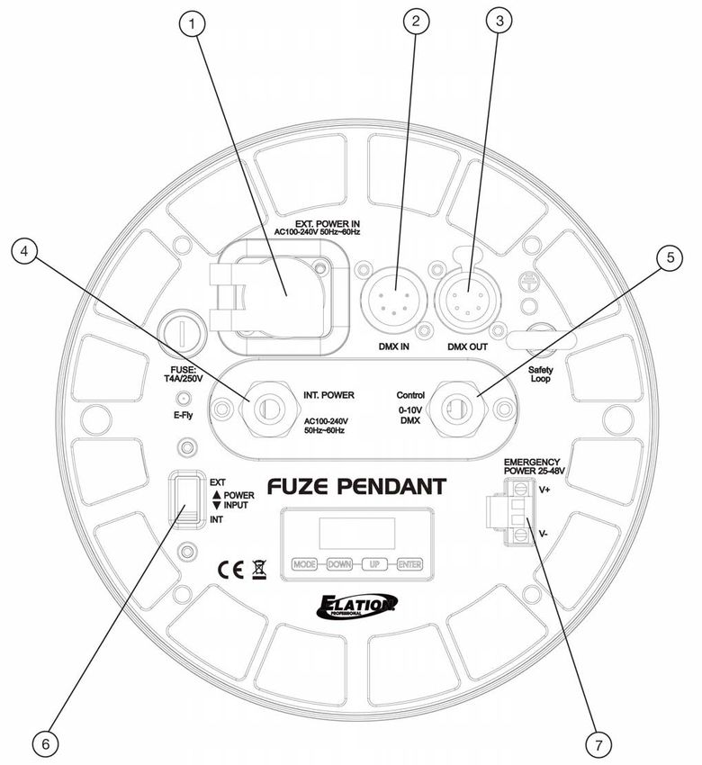
8OVERVIEW
1. Locking Power Connector 5. Wired DMX Cable Gland
2. DMX Input – 5-pin XLR Male 6. Power Input Switch
3. DMX Output – 5-pin XLR Female 7. Emergency Power Input Terminal
4. Wired Power Input Cable Gland
9OVERVIEW
POWER CONNECTIONS
Power may be provided to the fixture by means of an industry standard locking power connector
(1). Alternately, for more permanent installations, a power line may be wired to the fixture by
connecting a line to the wired power input cable gland (4). A wiring block is located directly behind
this gland, with wire terminals for Live (L), Neutral (N), and Floating Ground (FG). This terminal block
is accessed by removing the center plate in the connection panel.
Additionally, the fixture may be configured to draw power from either input by means of the power
input switch (6). The fixture will draw power from the locking power connector (1) when the switch
is set to the “EXT” position, or the wired power input cable gland (4) when the switch is set to the
“INT” position.
DMX CONNECTIONS
DMX communication to and from the fixture may be provided by the DMX 5-pin male XLR input (2)
and the DMX 5-pin female XLR output (3). Alternately, for more permanent installation, a DMX line
may be wired to the fixture by connecting the line to the wired DMX cable gland (5). A wiring block
is located directly behind this gland, with wire terminal for DMX +, DMX -, and DMX GND. This
terminal block is accessed by removing the center plate in the connection panel. The terminal block
also contains two additional terminals for 10V+ and 10V-, but these terminals are discussed in the
following section.
0-10V / CONTACT CLOSURE CONNECTION
The terminal block that is used for the hard-wired DMX connections also includes terminals for 10V+
and 10V-. These two terminals may be used to connect the fixture to a current sink 0-10V dimmer to
enable adjustment of lighting intensity, or they may be used to connect the fixture to a contact
closure such as a wall switch or an emergency alarm panel.
EMERGENCY POWER
The emergency power input terminal (7) can be connected to a 25-48V DC power source in order
to provide emergency lighting in the event of loss of AC power. The DC power source should be
rated for 15W or 20W in order to provide sufficient power for the fixture to operate for a minimum of
90 minutes. Please note that neither color nor light output will be adjustable when the fixture is
operating in this mode, as the fixture has been optimized for maximum runtime at the required light
levels.
Please note that it is the responsibility of the user to determine the system design, wiring, and
illumination levels required by law for emergency lighting systems in the locality in which the
system will be operating. Emergency lighting must comply with all applicable national, state,
and local standards.
10O P T I O N A L A C C E S S O R Y I N S TA L L AT I O N G U I D E L I N E S
LENS KIT
2 3
PLACE FIXTURE ON A STABLE SURFACE AND LET COOL FOR 15 MINUTES!
DO NOT OVER TIGHTEN SCREWS! DO NOT USE A POWER SCREWDRIVER!
1. Loosen screw on the side of lens bezel to open/release, as shown in the image on the left.
2. Carefully install lens in place, as shown in the image on the right.
3. Check lens is positioned correctly in the fixture then close/secure lens bezel.
11O P T I O N A L A C C E S S O R Y I N S TA L L AT I O N G U I D E L I N E S
YOKE BRACKET KIT
3
1 2
3
1
2
PLACE FIXTURE ON A STABLE SURFACE AND LET COOL FOR 15 MINUTES!
DO NOT OVER TIGHTEN SCREWS! DO NOT USE A POWER SCREWDRIVER!
1. Attach yoke spacer disc (x2) to fixture with (x2) screws each.
2. Attach yoke inner mounting disc (x2) to the yoke spacer discs with (x4) screws each.
3. Align yoke, yoke outer mounting disc (x2), and hand knob (x2) over the yoke inner mounting discs,
then insert and rotate hand knobs clockwise to secure yoke in desired position.
12O P T I O N A L A C C E S S O R Y I N S TA L L AT I O N G U I D E L I N E S
HALF AND FULL SNOOT KIT
PLACE FIXTURE ON A STABLE SURFACE AND LET COOL FOR 15 MINUTES!
DO NOT OVER TIGHTEN SCREWS! DO NOT USE A POWER SCREWDRIVER!
1. Attach snoot to the fixture lens bezel and secure in place with (x2) screws.
13O P T I O N A L A C C E S S O R Y I N S TA L L AT I O N G U I D E L I N E S
CEILING MOUNT KIT – SAFETY WARNINGS
The evaluation of a suitable installation surface such as wood, drywall or other materials is the
responsibility of the installer, architect, engineer or other skilled person involved in the mounting and
securing of the fixture.
The Fuze Pendant itself has a weight of 15.8lbs (7.2 kg), which the installation surface must be able
to support securely. If in any doubt regarding the suitability of the surface, all weight must be carried
by the hanging bracket, with the ceiling mount kit only utilized as a visual trim kit for a clean
installation. The ceiling kit / trim ring can be installed with or without the provided body support
plates.
The Fuze Pendant and ceiling kit are NOT plenum rated.
The Fuze Pendant must ALWAYS be secured by a secondary safety cable from its included safety
eyelet to an independent structural element. Such elements can be ceiling joists, concrete ceilings
and other structural systems which can secure the fixture in case of failure of the mounting surface
to carry the Fuze Pendant securely.
Failure to provide the secondary safety can lead to serious injury or death.
The secure installation of the Fuze Pendant is always the responsibility of the customer, as the
evaluation of surfaces and installation methods is beyond the scope of Elation Professional to
predict. A structural engineer should be consulted for all overhead installations of fixtures to provide
calculations and approval for weights, primary and safety attachment points and suitability of
surfaces and appropriate fastening methods.
Secure and structurally safe installation approved by an engineer is imperative for mounting the Fuze
Pendant into recessed ceilings.
Elation Professional is not responsible for the installation methods and choices of installation
surfaces.
Improper installation, unsuitable surfaces and failure to secure a secondary safety cable can
lead to serious injury or death.
14O P T I O N A L A C C E S S O R Y I N S TA L L AT I O N G U I D E L I N E S
CEILING MOUNT KIT - INSTALLATION
1. Open an 8.5-inch diameter hole in the desired ceiling panel. Insert the aluminum trim ring (A) through the hole
from the underside of the panel, then secure the trim ring in place with the included screws, washers, and support
brackets (B).
2. Lower the lighting fixture (A) into the trim ring (B) from above. Secure the lighting fixture in place by tightening
the four (4) thumb screws (C).
15O P T I O N A L A C C E S S O R Y I N S TA L L AT I O N G U I D E L I N E S
CEILING MOUNT KIT - INSTALLATION
3. Attach the body support plates (A) to the trim ring using the included screws and washers (B).
4. Install the entire assembly back into the ceiling at the desired location, making sure that the ends of the body
support plates (A) are resting on firmly on the ceiling support grid (B). Secure the body support plates in place
using the appropriate hardware.
16O P T I O N A L A C C E S S O R Y I N S TA L L AT I O N G U I D E L I N E S
CEILING MOUNT KIT – COMPONENT LIST
ITEM NO. ITEM QTY.
1 Body Support Plate 2
2 Trim Ring Support Bracket 2
3 Hex Screw, M4x10 8
4 Flat Head Washer, M4x8x0.8 8
5 Trim Ring 1
6 Thumb Screw, M6x10 4
17F I X T U R E I N S TA L L AT I O N G U I D E L I N E S
FLAMMABLE MATERIAL WARNING
Keep fixture minimum 5.0 feet (1.5m) away from flammable materials and/or pyrotechnics.
ELECTRICAL CONNECTIONS
A qualified electrician should be used for all electrical connections and/or installations.
MINIMUM DISTANCE TO OBJECTS/SURFACES IS 1 FOOT (0.3 METERS)
MINIMUM DISTANCE OF FLAMMABLE MATERIALS
FROM THE SURFACE IS 1.6 FEET (0.5 METER)
MAXIMUM AMBIENT TEMPERATURE 113° F (45°C)
DO NOT INSTALL THE FIXTURE IF YOU ARE NOT QUALIFIED TO DO SO!
Fixture MUST be installed following all local, national, and country commercial electrical and
construction codes and regulations.
Before rigging/mounting a single fixture or multiple fixtures to any metal truss/structure or placing
the fixture(s) on any surface, a professional equipment installer MUST be consulted to determine if
the metal truss/structure or surface is properly certified to safely hold the combined weight of the
fixture(s), clamps, cables, and accessories.
Overhead rigging requires extensive experience, including amongst others calculating working load
limits, installation material being used, and periodic safety inspection of all installation material and
the fixture. If you lack these qualifications, do not attempt the installation yourself. Improper
installation can result in bodily injury.
Fixture(s) should be installed in areas outside walking paths, seating areas, or away from areas
where unauthorized personnel might reach the fixture by hand.
NEVER stand directly below the fixture(s) when rigging, removing or servicing.
Overhead fixture installation must always be secured with a secondary safety attachment, such as
an appropriately rated safety cable.
Allow approximately 15 minutes for the fixture to cool down before serving.
18F I X T U R E I N S TA L L AT I O N G U I D E L I N E S
RIGGING
Overhead rigging requires extensive experience, including calculating working load limits, knowledge
of installation material being used, and periodic safety inspection of all installation material and the
fixture, among other things. If you lack these qualifications, do not attempt the installation yourself.
Improper installation can result in bodily injury.
CLAMP INSTALLATION
When mounting fixture to truss, be sure to secure an appropriately rated professional grade rigging
clamp to the included Pendant Bracket or the optional Yoke Bracket using an M10 screw fitted
through the center hole. The fixture provides a built-in rigging point for a SAFETY CABLE. Be sure
to only use one of the designated rigging points for the safety cable and never secure a safety cable
to the Pendant or Yoke Brackets.
ALWAYS ATTACH AN APPROPRIATELY RATED SAFETY CABLE (NOT INCLUDED) THAT
MEETS ALL LOCAL, NATIONAL, AND COUNTRY CODES AND REGULATIONS WHENEVER
INSTALLING FIXTURE IN A SUSPENDED ENVIRONMENT!
SAFETY CABLE
ATTACHMENT POINT
ALWAYS ATTACH A SAFETY CABLE
WHENEVER INSTALLING THIS FIXTURE IN
A SUSPENDED ENVIRONMENT TO
ENSURE FIXTURE WILL NOT DROP IF
MOUNTING / RIGGING HARDWARE FAILS.
19E-FLY WIRELESS SET UP GUIDELINES
There are many factors that affect and/or interrupt a wireless signal such as walls, glass, metal,
objects, and people. Therefore, it is highly recommended to:
• Install devices a minimum of 9.8 ft. (3m) above audiences and/or ground level
• Adjust the wireless antenna in a vertical upright position
• Position devices in direct line of sight of the controlling E-FLY device
Careful planning and testing of the selected installation location is critical to ensure optimum and
reliable wireless operation.
20SYSTEM MENU
The fixture includes an easy to navigate system menu. The OLED control panel display located at
the top of the fixture (see image below), provides access to the main system menu where all
necessary system adjustments are made to the fixture. During normal operation, pressing the MODE
button once will access the fixture’s main menu. Once in the main menu you can navigate through
the different functions and access the sub-menus with the DOWN and UP buttons. Once you reach
a field that requires adjusting, press the ENTER button to activate that field and use the DOWN and
UP buttons to adjust the field. Pressing the ENTER button once more will confirm the setting. Exit
the main menu at any time without making any adjustments by pressing the MODE button.
To access the system menu, press and hold the MODE button for 3 seconds. The OLED display will
shut OFF automatically approximately 1 minute from the last button press.
21SYSTEM MENU
ELATION FUZE PENDANT™ - SYSTEM MENU
Supports Software Versions: ≥ 1.06
DMX Address A001 ~ AXXX
Dimmer1CH, Dimmer Color 4CH, RGBWL 5CH,
DMX Channel Mode RGBWL 16bit 10CH, Standard 10CH, Extended
DMX Settings 17CH, HSI 4CH, HSI Extended 9CH
No DMX Status Hold Last, Fade to Black, Standalone, 0-10V
Priority DMX, 0-10V
Dimmer 0-100%
ColorTemperature 2400-8500K
Swatch Book, Color Scroll, Color C-Scroll,
Virtual Color
Standalone Random Slots
Fade Time 0-60s (10sec)
Use 0-10V ON / OFF
Alarm Mode ON / OFF
Primary ON / OFF
Secondary ON / OFF
Standard, Stage, TV, 0s, 0.1s, 0.2s, 0.3s, 0.4s, 0.5s,
0.6s, 0.7s, 0.8s, 0.9s, 1.0s,
Dim Modes Architectural, Theatre, 1.5s, 2.0s, 3.0s, 4.0s, 5.0s,
Stage 2, Dim Speed 6.0s, 7.0s, 8.0s, 9.0s, 10.0s
Dim Curves Linear, Square, Square Inverse, S-Curve
Set E-FLY Channel 00-14
E-FLY Settings
Enable E-FLY YES / NO
1200Hz, 900-1500Hz, 2500Hz, 4000Hz, 5000Hz,
LED Refresh Rate
6000Hz, 10KHz, 15KHz, 20KHz, 25KHz
LED Power Limit 50, 60, 70, 80, 90, 100%
ScreenSaverDelay 1-10
Display Screen Lock OFF, 30 Secs, 1-10mins
Personality RotateDisplay180 YES / NO
P
Red 000-255
a
Green 000-255
s
Calibration Blue 000-255
s
White 000-255
c
Lime 000-255
o
Service d Factory Restore YES / NO
e
0 Edit RDM UID xxxxxx
5
0
22Red 000-255
Green 000-255
Blue 000-255
Manual White 000-255
Control Lime 000-255
Dimmer 000-255
Dimmer Fine 000-255
Strobe 000-255
FixtureLifeTime Power On Time xxxxxx Hours
PowrOnTimAbleRes xxxxxx Hours
FixLastRunTime
PowerOnTimeReset Passcode 038
Total Lamp Hours xxxxxx Hours
Current xxxF / xxxC
Max Resettable xxxF / xxxC
Information Fixture Temp LED's MaxNotResettable xxxF / xxxC
Passcode
LastMaxTempReset
038
DMX Values Dimmer 000-255
Product ID’s RDM UID xxxxxx
Fixture Errors Error1, Error2, …
Error Logs Passcode
Reset Error Log YES / NO
050
Software Version V1.06
23SYSTEM MENU – DMX SETTINGS
DMX ADDRESS
This function allows the user to define the DMX address of the fixture. This value is displayed as
“AXXX” where XXX represents a 3-digit numerical values from 001 – 512.
DMX CHANNEL MODE
This function allows the user to define the DMX channel mode in which the fixture will operate. See
the DMX Channel Functions section for full details on which functions are included in each DMX
channel mode.
NO DMX STATUS
This function allows the user to define the behavior of the fixture in the event that DMX signal is lost.
The user may select from one of the following options:
- Hold Last: The fixture adheres to the color and intensity settings that were in use immediately
before DMX communication was lost, and continues to do so until DMX communication is re-
established or a power cycle occurs. Please note that this mode is the fixture’s default setting.
- Fade to Black: The fixture fades to 0% intensity in the time span dictated by the Standalone
Fade Time setting. Please refer to the SYSTEM MENU – STANDALONE section for details.
- Standalone: The fixture reverts to the Color Temperature and Virtual Color settings defined in
the Standalone menu, in a time span dictated by the Standalone Fade Time setting. Please refer
to the SYSTEM MENU – STANDALONE section for details.
- 0-10V: The fixture reverts to the Color Temperature and Virtual Color settings defined in the
Standalone menu, with the output intensity dictated by the 0-10V input.
PRIORITY
This function allows the user to select whether the DMX signal or the 0-10V voltage level determines
the intensity of the light output.
24SYSTEM MENU – STANDALONE
The Standalone System Menu allows the user to define how the fixture will behave when operating
without DMX control. Color settings located in this menu also define the fixture output when operating in
1-Channel DMX Mode.
DIMMER
This function is used to set the light output intensity of the fixture, from 0% to 100% of maximum output
level.
COLOR TEMPERATURE
This function is used to set the color temperature, and ranges from 2400 to 8500 K in intervals of 100 K.
VIRTUAL COLOR
This function is used to select from a range of predefined color settings shown in the Virtual Gel Swatch
Book table on page 36.
- Swatch Book: Select a single display color from the table.
- Color Scroll: Scrolls through all the colors in forward order of the Value listed in the Virtual Gel
Swatch Book table shown on page 36. Scroll speed is adjustable from 0à22 (slowest to fastest).
- Color C-Scroll: Scrolls through all the colors in reverse order of the Value listed in the Virtual Gel
Swatch Book table shown on page 36. Scroll speed is adjustable from 0à22 (slowest to fastest).
- Random Slots: Scrolls through all the colors shown on the Virtual Gel Swatch Book table shown on
page 36 in random order. Scroll speed can be set to Fast, Medium, or Slow.
FADE TIME
This function is used to define the time span in which the fixture transitions to the output color and
intensity that have been selected in the Color Temperature and Virtual Color settings, ensuring a
smooth transition between operation in DMX mode and Standalone mode. Available Fade Time options
range from 0 seconds to 60 seconds, in 1-second intervals. The default setting for this fixture is 10
seconds.
0-10V CONTACT / ALARM CONTACT
These functions control the way that the fixture interprets the signal from the 0-10V connector. The 0-10V
CONTACT setting is used to enable or disable the fixture’s ability to use the 0-10V input to determine the
intensity of light output. Please note that if this feature is enabled, the fixture will adhere to the settings
selected in the Color Temperature and Virtual Color functions of the Standalone System Menu.
Alternately, the ALARM CONTACT setting is used to enable or disable the fixture’s ability to activate
Standalone mode when input is received from the 0-10V connector. DMX control will simultaneously be
disabled when the fixture enters this mode. Common uses for this feature include emergency lighting
applications or a master power switch for repair and maintenance purposes.
25DIMMER MODES
DIMMER
100%
50%
10%
0%
Time (ms)
0 Sec Rise Time Down Time
0 sec Fade Time 1 sec Fade Time
255 255
Dimming Curve
Ramp Effect
0 0
Rise Time (ms) Down Time (ms) Rise Time (ms) Down Time (ms)
Standard (default) 0 0 0 0
Stage 780 1100 1540 1660
TV 1180 1520 1860 1940
Architectural 1380 1730 2040 2120
Theatre 1580 1940 2230 2280
Stage 2 0 1100 0 1660
100% 100% 100% 100%
Output
Output
Output
Output
0 0 0 0
DMX % DMX % DMX % DMX %
LINEAR SQUARE INVERSE SQUARE S-CURVE
26DMX CHANNEL FUNCTIONS
ELATION FUZE PENDANT™
RGBWL MODES - DMX Channel Values / Functions (17 Total DMX Channels)
Supports Software Versions: ≥ 1.06
Features subject to change without notice.
4CH 10CH
1CH 5CH 10CH 17CH
Dimmer RGBWL Value Function Default Snap
Dimmer RGBWL Standard Extended
Color 16bit
Strobe
0 - 31 Closed
32 - 63 Open
64 - 95 Strobe (slow → fast)
1 1 96 - 127 Open 50 X
129-159 Pulse (slow → fast)
160 - 191 Open
192 - 223 Random (slow → fast)
224 - 255 Open
Dimmer
1 1 2 2 0
0 - 255 0 → 100%
Dimmer Fine
2 3 3 0
0 - 255 0 → 100%
274CH 10CH
1CH 5CH 10CH 17CH
Dimmer RGBWL Value Function Default Snap
Dimmer RGBWL Standard Extended
Color 16bit
Red
1 1 4 4 255
0 - 255 0 → 100%
Red Fine
2 5 255
0 - 255 0 → 100%
Green
2 3 5 6 255
0 - 255 0 → 100%
Green Fine
4 7 255
0 - 255 0 → 100%
Blue
3 5 6 8 255
0 - 255 0 → 100%
Blue Fine
6 9 255
0 - 255 0 → 100%
White
4 7 10 255
0 - 255 0 → 100%
White Fine
8 11 255
0 - 255 0 → 100%
Lime
5 9 12 255
0 - 255 0 → 100%
Lime Fine
10 13 255
0 - 255 0 → 100%
CTO
0-23 Open
3 7 14 CTO 2400K - 8500K (see Color 0
24 -85
Temperature Table)
86-255 8500K
Color Wheel
0 Open
Virtual Swatch Book (see Virtual Gel
1-179
Swatch Book Table)
Color Scroll
180-201 Clockwise, fast → slow
202-207 Stop
4 8 15 208-229 0
Counter-clockwise, slow → fast
230-234 Open
Random Slots
235-239 Fast
240-244 Medium
245-249 Slow
250-255 Open
284CH 10CH
1CH 5CH 10CH 17CH
Dimmer RGBWL Value Function Default Snap
Dimmer RGBWL Standard Extended
Color 16bit
Dim Modes
0 - 20 Standard
21 - 40 Stage
41 - 60 TV
61- 80 Architectural
81- 100 Theatre
101- 120 Stage 2
Dimmer Delay Time
121 0s
122 0.1s
123 0.2s
124 0.3s
125 0.4s
126 0.5s
127 0.6s
9 16 0 X
128 0.7s
129 0.8s
130 0.9s
131 1.0s
132 1.5s
133 2.0s
134 3.0s
135 4.0s
136 5.0s
137 6.0s
138 7.0s
139 8.0s
140 9.0s
141 10s
142 - 255 Idle
294CH 10CH
1CH 5CH 10CH 17CH
Dimmer RGBWL Value Function Default Snap
Dimmer RGBWL Standard Extended
Color 16bit
Control
0-99 Idle
Change Refresh Rate (Hz) (Hold 1s)
100 900
101 910
102 920
103 930
104 940
105 950
106 960
107 970
108 980
109 990
110 1000
111 1010
112 1020
113 1030
114 1040
115 1050
10 17 116 1060 0 X
117 1070
118 1080
119 1090
120 1100
121 1110
122 1120
123 1130
124 1140
125 1150
126 1160
127 1170
128 1180
129 1190
130 1200
131 1210
132 1220
133 1230
134 1240
135 1250
304CH 10CH
1CH 5CH 10CH 17CH
Dimmer RGBWL Value Function Default Snap
Dimmer RGBWL Standard Extended
Color 16bit
136 1260
137 1270
138 1280
139 1290
140 1300
141 1310
142 1320
143 1330
144 1340
145 1350
146 1360
147 1370
148 1380
149 1390
150 1400
151 1410
152 1420
153 1430
154 1440
155 1450
156 1460
157 1470
158 1480
10 17 0 X
159 1490
160 1500
161 2500
162 4000
163 5000
164 6000
165 10000
166 15000
167 20000
168 25000
169-200 Idle
201-210 Dimmer Curve Linear (default)
211-220 Dimmer Curve Square
221-230 Dimmer Curve Inverse Square
231-240 Dimmer Curve S-Curve
241 Internal program 1 (Scene 1-8)
242 Internal program 2 (Scene 9-16)
243 Internal program 3 (Scene 17-24)
244 Internal program 4 (Scene 25-32)
245 Internal program 5 (Scene 33-40)
246 Internal program 6 (Scene 41-48)
247 Internal program 7 (Scene 49-56)
248-255 Idle
31ELATION FUZE PENDANT™
HSI MODES - DMX Channel Values / Functions (9 Total DMX Channels)
Supports Software Versions: ≥ 1.06
Features subject to change without notice.
HSI HSI Extended
Value Function Default Snap
4CH 9CH
Strobe
0 - 31 Closed
32 - 63 Open
64 - 95 Strobe (slow → fast)
1 96 - 127 Open 50 X
129-159 Pulse (slow → fast)
160 - 191 Open
192 - 223 Random (slow → fast)
224 - 255 Open
Intensity
1 2 0
0 - 255 0 → 100%
Intensity Fine
2 3 0
0 - 255 0 → 100%
Hue
3 4 255
0 - 255 0 → 100%
Saturation
4 5 255
0 - 255 0 → 100%
CTO
0-23 Open
6 0
24 -85 CTO 2400K - 8500K (see Color Temperature Table)
86-255 8500K
Color Wheel
0 Open
1-179 Virtual Swatch Book (see Virtual Gel Swatch Table)
Color Scroll
180-201 Clockwise, fast → slow
202-207 Stop
7 208-229 Counter-clockwise, slow → fast 0
230-234 Open
Random Slots
235-239 Fast
240-244 Medium
245-249 Slow
250-255 Open
32HSI HSI Extended
Value Function Default Snap
4CH 9CH
Dim Modes
0 - 20 Standard
21 - 40 Stage
41 - 60 TV
61- 80 Architectural
81- 100 Theatre
101- 120 Stage 2
Dimmer Delay Time
121 0s
122 0.1s
123 0.2s
124 0.3s
125 0.4s
126 0.5s
127 0.6s
8 0 X
128 0.7s
129 0.8s
130 0.9s
131 1.0s
132 1.5s
133 2.0s
134 3.0s
135 4.0s
136 5.0s
137 6.0s
138 7.0s
139 8.0s
140 9.0s
141 10s
142 - 255 Idle
33HSI
HSI Value Function Default Snap
Extended
Control
0-99 Idle
Change Refresh Rate (Hz) (Hold 1s)
100 900
101 910
102 920
103 930
104 940
105 950
106 960
107 970
108 980
109 990
110 1000
111 1010
112 1020
113 1030
114 1040
115 1050
9 116 1060 0 X
117 1070
118 1080
119 1090
120 1100
121 1110
122 1120
123 1130
124 1140
125 1150
126 1160
127 1170
128 1180
129 1190
130 1200
131 1210
132 1220
133 1230
134 1240
135 1250
34HSI
HSI Value Function Default Snap
Extended
136 1260
137 1270
138 1280
139 1290
140 1300
141 1310
142 1320
143 1330
144 1340
145 1350
146 1360
147 1370
148 1380
149 1390
150 1400
151 1410
152 1420
153 1430
154 1440
155 1450
156 1460
157 1470
158 1480
9 0 X
159 1490
160 1500
161 2500
162 4000
163 5000
164 6000
165 10000
166 15000
167 20000
168 25000
169-200 Idle
201-210 Dimmer Curve Linear (default)
211-220 Dimmer Curve Square
221-230 Dimmer Curve Inverse Square
231-240 Dimmer Curve S-Curve
241 Internal program 1 (Scene 1-8)
242 Internal program 2 (Scene 9-16)
243 Internal program 3 (Scene 17-24)
244 Internal program 4 (Scene 25-32)
245 Internal program 5 (Scene 33-40)
246 Internal program 6 (Scene 41-48)
247 Internal program 7 (Scene 49-56)
248-255 Idle
35COLOR TEMPERATURE
VALUE COLOR TEMP (K) VALUE COLOR TEMP (K)
24 2400 55 5500
25 2500 56 5600
26 2600 57 5700
27 2700 58 5800
28 2800 59 5900
29 2900 60 6000
30 3000 61 6100
31 3100 62 6200
32 3200 63 6300
33 3300 64 6400
34 3400 65 6500
35 3500 66 6600
36 3600 67 6700
37 3700 68 6800
38 3800 69 6900
39 3900 70 7000
40 4000 71 7100
41 4100 72 7200
42 4200 73 7300
43 4300 74 7400
44 4400 75 7500
45 4500 76 7600
46 4600 77 7700
47 4700 78 7800
48 4800 79 7900
49 4900 80 8000
50 5000 81 8100
51 5100 82 8200
52 5200 83 8300
53 5300 84 8400
54 5400 85 8500
36VIRTUAL GEL SWATCH BOOK
VALUE FILTER# COLOR VALUE FILTER# COLOR
1 7 Pale Yellow 31 126 Mauve
2 103 Straw 32 49 Medium Purple
3 151 Gold Tint 33 58 Lavender
4 100 Spring Yellow 34 199 Palace Blue
5 10 Medium Yellow 35 119 Dark Blue
6 101 Yellow 36 132 Medium Blue
7 104 Deep Amber 37 120 Deep Blue
8 15 Deep Straw 38 165 Daylight Blue
9 179 Loving Amber 39 161 Slate Blue
10 21 Gold Amber 40 118 Light Blue
11 105 Orange 41 68 Sky Blue
12 158 Deep Orange 42 143 Pale Navy Blue
13 22 Dark Amber 43 131 Marine Blue
14 778 Millennium Gold 44 115 Peacock Blue
15 135 Deep Golden Amber 45 172 Lagoon Blue
16 24 Scarlet 46 116 Medium Blue Green
17 106 Primary Red 47 90 Dark Yellow Green
18 26 Bright Red 48 139 Primary Green
19 27 Medium Red 49 122 Fern Green
20 19 Fire 50 89 Moss Green
21 157 Pink 51 124 Dark Green
22 36 Medium Pink 52 88 Lime Green
23 111 Dark Pink 53 138 Pale Green
24 128 Bright Pink 54 203 Quarter CT Blue
25 148 Bright Rose 55 202 Half CT Blue
26 332 Special Rose Pink 56 201 FULL CT Blue
27 793 Vanity Fair 57 200 Double CT Blue
28 113 Magenta 58 206 Quarter CT Orange
29 46 Dark Magenta 59 205 Half CT Orange
30 48 Rose Purple 60 204 FULL CT Orange
37ERROR CODES
Error Codes subject to change without notice.
ERROR CODES DESCRIPTION
Temp Error These messages will appear if there is a temperature and/or
0-10V Error voltage malfunction.
38SPECIFICATIONS
SOURCE
230W 5-in-1 RGBWL (Red, Blue, Green, White, Lime) LED Engine
50,000 Hour Average LED Life*
*Test lab conditions. May vary depending on several factors including but not limited to:
Environmental Conditions, Power/Voltage, Usage Patterns (On-Off Cycling), Control, and Dimming.
EFFECTS
Color Temperature Control 2,400K – 8,500K
Virtual Color Swatch Book
Dimmer, Dimmer Color, RGBWL, RGBWL 16-bit, Standard, Extended, HSI, & HSI Extended Control Options
Variable 16-bit Dimming Curve Modes
High Speed Electronic Shutter and Strobe
DMX and Menu adjustable LED Refresh Rate Frequency
CONTROL / CONNECTIONS
8 DMX Channel Modes
Standalone and Primary, Secondary Modes
RDM (Remote Device Management)
0-10V Dimming (Current-Sink)
E-FLY™ Internal Extended Range Wireless DMX Transceiver
4 Button Control Panel and OLED Menu Display
Locking 5pin XLR Connector In/Out
Locking IP65 Power Connector In
3pin Bare Wire Terminal Block for Power
5pin Bare Wire Terminal Block for 0-10V, DMX
2pin Bare Wire Terminal Block for 48V Emergency Battery Input
SIZE / WEIGHT
Length: 12.5" (318mm)
Diameter: 7.8" (197mm)
Weight: 15.8lbs. (7.2 kg)
ELECTRICAL / THERMAL
AC 100-240V - 50/60Hz
230W Max Power Consumption
14°F to 113°F (-10°C to 45°C)
APPROVALS / RATINGS
CE | cETLus | IP20
Specifications and improvements in the design of this unit and this manual are subject to change without notice.
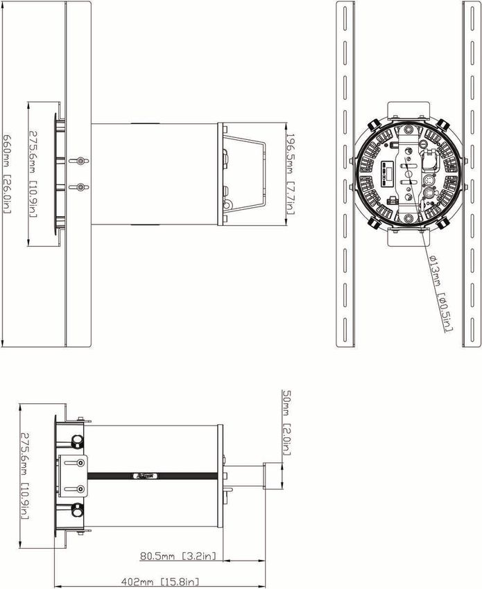
39DIMENSIONAL DRAWINGS – Pendant Bracket Attached (Not to Scale)
Specifications and improvements in the design of this unit and this manual are subject to change without notice.
40DIMENSIONAL DRAWINGS – Yoke Bracket Attached (Not to Scale)
Specifications and improvements in the design of this unit and this manual are subject to change without notice.
41DIMENSIONAL DRAWINGS – Recessed Ceiling Kit Attached (Not to Scale)
Specifications and improvements in the design of this unit and this manual are subject to change without notice.
42DIMENSIONAL DRAWINGS – Half Snoot Attached (Not to Scale)
Specifications and improvements in the design of this unit and this manual are subject to change without notice.
43DIMENSIONAL DRAWINGS – Full Snoot Attached (Not to Scale)
Specifications and improvements in the design of this unit and this manual are subject to change without notice.
44OPTIONAL ACCESSORIES
SKU (USA) SKU (EU) ITEM
FPL50 1237000228 Fuze Pendant Lens 50°
FPL40 1237000243 Fuze Pendant Lens 40°
FPL25 1237000229 Fuze Pendant Lens 25°
FPCMK 1237000244 Fuze Pendant Ceiling Mount Kit
FPYMK 1237000245 Fuze Pendant Yoke Mount Kit
FPHS 1237000246 Fuze Pendant Half Snoot
FPFS 1237000247 Fuze Pendant Full Snoot
FCC STATEMENT
This device complies with Part 15 of the FCC Rules. Operation is subject to the following two conditions: (1) this device
may not cause harmful interference, and (2) this device must accept any interference received, including interference that
may cause undesired operation.
FCC RADIO FREQUENCY INTERFERENCE WARNINGS & INSTRUCTIONS
This product has been tested and found to comply with the limits as per Part 15 of the FCC Rules. These limits are
designed to provide reasonable protection against harmful interference in a residential installation. This device uses and
can radiate radio frequency energy and, if not installed and used in accordance with the included instructions, may
cause harmful interference to radio communications. However, there is no guarantee that interference will not occur in a
particular installation. If this device does cause harmful interference to radio or television reception, which can be
determined by turning the device off and on, the user is encouraged to try to correct the interference by one or more of
the following methods:
• Reorient or relocate the device.
• Increase the separation between the device and the receiver.
• Connect the device to an electrical outlet on a circuit different from which the radio receiver is connected.
• Consult the dealer or an experienced radio/TV technician for help.
Europe Energy Saving Notice
Energy Saving Matters (EuP 2009/125/EC)
Saving electric energy is a key to help protecting the environment. Please turn off all electrical products when they are
not in use. To avoid power consumption in idle mode, disconnect all electrical equipment from power when not in use. Thank
you
45USA# FUZ260 EU# 1237000225 UPC# 810008260869 ITF-14# 10810008260866
You can also read