KTV 3/KTV 4 automatic revolving doors - Intelligent system solutions for individual requirements - dormakaba
←
→
Page content transcription
If your browser does not render page correctly, please read the page content below

KTV 3/KTV 4
automatic revolving doors

                            Intelligent system
                            solutions
                            for individual
                            requirements
dormakaba   KTV 3 / KTV 4

            Our commitment to a sustainable future
            One of our core values is being environmentally conscious. dormakaba’s goal is
            to make quality products that are produced in an energy- and resource-saving
            manner, use a high proportion of recyclables and have a long product life.
            At the product level, the sustainability of buildings is calculated using the
            Environmental Product Declaration (EPD) based on overall life cycle assessments.
            The complete EPD is available at www.dormakaba.com.

2
Introduction

Contents

                             Introduction                                       05
                             KTV revolving doors: Perfect design and function   06

                             Configuration options
                             System dimensions                                  08
                             Turnstile versions                                 09
                             Locks and anti-intruder protection                 10
                             Door wings, drum walls and night shield            11
                             Upper and lower ceiling assembly                   12
                             Surfaces, coatings and floor coverings             13
                             Direct drive, function module, operating modes     14

                             Planning
                             Throughflow capacity in theory and practice        16
                             Detailed dimensions                                18
                             Floor ring and building ground connection          20
                             Façades and building connections                   22
                             Safety equipment and functional elements           24
                             Air curtain system                                 26
                             Electrical connection                              28
                             KTV equipment and combinations at a glance         30

Note on product illustrations in the brochure
The product illustrations in the brochure are exemplary representations
showing the current state of development. Depending on the version,
the illustrations may differ from the actual products.

                                                                                            3
dormakaba   KTV 3 / KTV 4

4
Introduction

First impressions count. A building is
entered for the first time via the main
entrance. That is why its visual
appearance, feel and ease of use are
essential components. Undisturbed traffic
flow, an improved indoor climate, noise
attenuation as well as high levels of
security and reliability are crucial
functional requirements. KTV revolving
doors perfectly combine design and
function with the designated architecture.
Designed according to your requirements
and manufactured for sophisticated
entrance areas.

                                                 5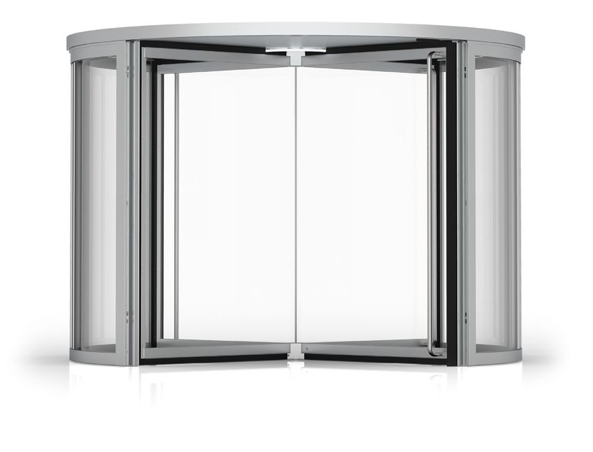
dormakaba                            KTV 3 / KTV 4

KTV revolving doors
The perfect combination of design
and function

KTV revolving doors from dormakaba are characterised          Advantages at a glance:
by their shallow ceiling assembly – only 100 mm – with an     • Harmonious design with concealed operating
integrated LED light ring. Despite the small dimensions, it     elements, sensors and LED light ring
is possible to combine the doors with a concealed electro-    • Fits perfectly into predetermined architecture,
mechanical locking device and additional night shield. The      especially mullion-transom façades
low-wear KT FLEX Direct drive unit is capable of handling     • Easy access to all drive components
high visitor frequencies and is at once durable and             despite shallow 100-mm ceiling structure
economical. Each system is planned and manufactured           • Low-wear, low-maintenance and low-noise
according to individual customer specifications and offers      direct drive
multifarious equipment options.                               • Individually adjustable size, operating mode
                                                                and function
                                                              • For customised integrated door systems from a
                                                                single source; can be combined with many other
                                                                dormakaba products, including the door automation,
                                                                preventive fire protection, escape route solutions
                                                                or access control ranges

6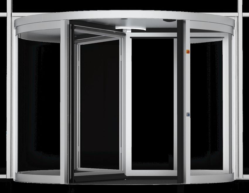
Introduction

                             02

01

100 mm. Unique and elegant.
Cost-effective and versatile.
Direct drive in shallow ceiling assembly
The electro-magnetic KT FLEX Direct drive unit is low-
noise, wear-resistant and low-maintenance. The brush-
less, gearless drive block allows for a ceiling assembly with
a minimal height of only 100 mm. The shallow design thus
fits elegantly into the architecture. The operating mode
determines the turnstile drive – manual, power assisted
or fully automatic – as well as the rotation speed.

Improved building climate control
After usage, the revolving doors rotate the door wing to
the rest position. A double row of sealing brushes on the
door wings improves the building climate even at high                                                                               03
wind loads. Thanks to the individually adjustable façade
closures, the system blends harmoniously into predeter-
mined building structures.

Anti-intruder protection to class RC2
Locking the turnstile prevents unauthorised access. The
optional night shield also increases anti-intruder protec-
tion. It is formed of one or two sliding panels which seal
the outer entrance to the system. A version up to resis-
tance class RC2 in accordance with EN 1627 is available.

                                                                Illustrations show an example of a 4-wing KTV 4 revolving
                                                                door with a fine-framed turnstile and an external night shield.
                                                                01 Ceiling assembly cross section
                                                                02 Direct drive and LED light ring
                                                                03 Door system with closed, external night shield

         Individual planning service                                       Quick and easy installation
         Each door system represents an individual and                     Prefabricated components mean the KTV
         integral part of the architecture. In view of                     revolving door can be installed quickly, easily
         diverse challenges, we offer you flexible options                 and smoothly. Further, no welding needs to be
         for KTV revolving doors that will solve even the                  performed on the floor ring. Ideal for specific
         most demanding tasks.                                             processes in new buildings and for refurbishment
                                                                           projects.

                                                                                                                                    7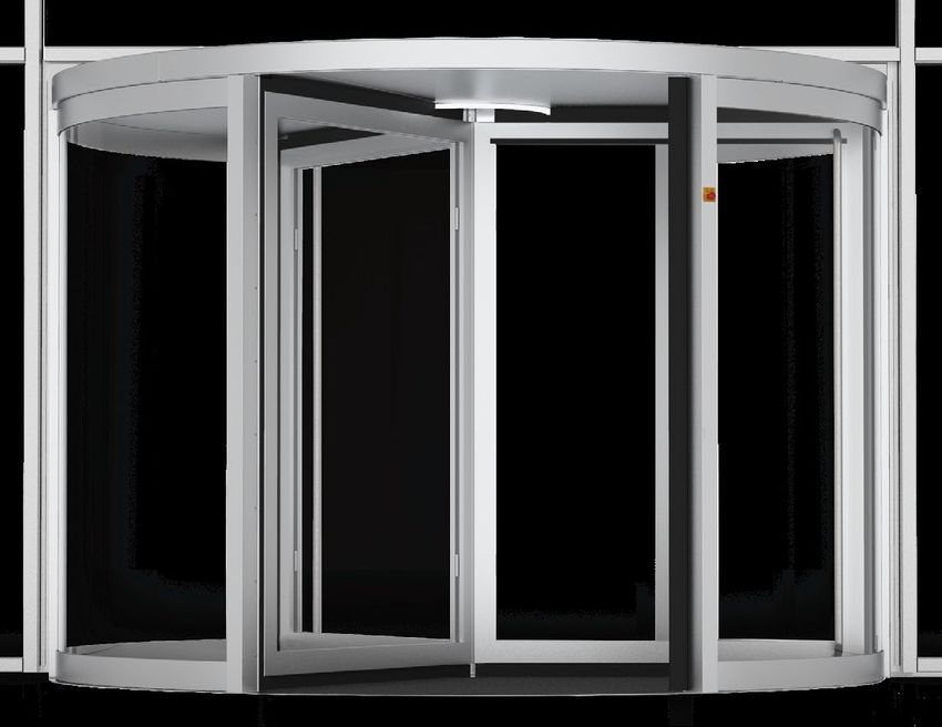
dormakaba                                   KTV 3 / KTV 4

Variety of KTV combinations
System dimensions and versions at
a glance

                                             01      2,000 to max. 3,800 mm                                      03 02

                                                                                                                 ≥ 100 mm

                                                                                                                            2,100 to max. 4,000 mm

The illustration shows an example outer view of a
3-wing KTV 3 revolving door with circumferentially
                                                            Variable dimensions for greater flexibility
framed wings.
                                                            The possible dimensions of a KTV revolving door depend on the
                                                            number and design of the door wings as well as the selected surface
                                                            finish. Detailed information regarding the design can be found in the
                                                            planning section of this brochure.

                                                            System dimensions
                                                            01 Internal diameter       W = 2,000 to max. 3,800 mm
                                                            02 Clear passage height    LH = 2,100 to max. 4,000 mm
                                                            03 Canopy height           CH ≥ 100 to max. 1,000 mm

8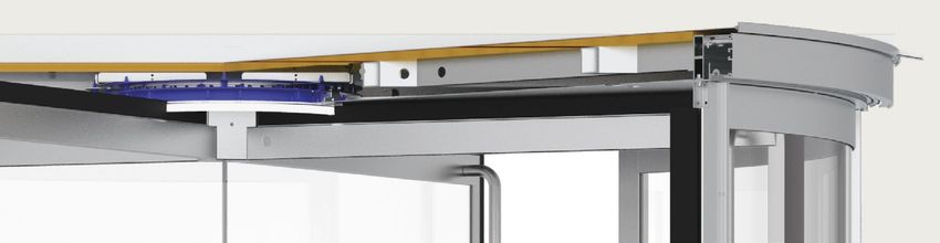
Configuration options

                              01

                              02                              03

                                                                           4-wing revolving door KTV 4
                                                                           01 100 mm canopy height
                                                                           02 Circumferentially framed door wings
                                                                           03 Drum wall

Turnstile versions

3- or 4-wing turnstile
                                                    °09                      60°     60°
                                                                                     °06                        90°
                                                                                                                90°
The KTV turnstile can be equipped with three or four door wings.
The advantage of the 3-wing door is that it provides more space in
the individual segments. The lower weight also reduces the effort
needed to enter manual and power-assisted doors. In addition, with
3-wing doors, higher clear passage heights are practicable, which            60°
                                                                             60°     60°
                                                                                     60°                            90°
                                                                                                                    90°   90°
                                                                                                                          90°
makes particularly streamlined door designs possible.
4-wing doors offer wider entrance and exit areas to facilitate
simultaneous entering and exiting of the building. With a higher
number of seals toward the posts, such doors also provide better
protection against draughts, noise and external climatic influences
when in rest position.

Transport opening
This function serves as a clear passage for bulky objects in order to
temporarily increase the throughflow capacity and for continuous
ventilation in corresponding weather conditions. A tool can be used
to loosen and collapse one or – in the case of KTV 4 – two door wings
of the turnstile.

Bookfold/escape route opening
If a defined force is exceeded, the door wings become collapsible
in both directions. This means the building can be exited rapidly
through both sides of the door, regardless of the rotation direction.
Depending on the country and local regulations, a system equipped
with collapsible wings may also be suitable for use in escape routes
and emergency exits.

Fine-framed turnstile
To achieve a particularly transparent appearance, a fine-framed, rigid
door wing may be used. Reinforced 12-mm toughened safety glass
(TSG) makes it possible to dispense with disruptive profiles in the
central door axis. The door is locked via a manual floor locking device.

                                                                                                                                9
dormakaba KTV 3 / KTV 4
01
02
°09 60° °06 90°
03 04 05
60° 90°
°09 °06
4-wing door system KTV 4
01 White melamine dust cover
02 100 mm canopy height
03 Circumferentially framed door wing
04 External night shield in
semi-closed position
05 Drum wall
Locking devices and night-shields
°09 60° °06 90°
Manual locking
The turnstile is latched against unauthorised entry by a rod lock
system concealed in the door wing. With a fine-framed turnstile,
a floor locking device is used.
Electro-mechanical locking
After changing the program switch, the door wings are automatically
positioned and closed: an electro-mechanical locking device installed
in the ceiling assembly engages a solid tab on the upper edge of the
door wing and locks the turnstile. The door may be released for
individual entry using the night/bank function. Sensors or push
buttons prevent unintentionally trapping of someone.
Manual or automatic night shield
A night shield is ideal for keeping out uninvited guests, leaves or
clogging. Once the revolving door has been powered off, operation
and locking are performed manually or automatically via an electro-
mechanical night shield. Doors with a night shield can be equipped
with suitable components, e.g. special types of glass and locking
devices, to comply with resistance class RC2 in accordance with
EN 1627.
Internal night shield
• Door system can be offset off-centre to the façade axis
• Manual night shield (canopy height CH min. 200 mm) and
automatic night shield (canopy height CH min. 300 mm)
External night shield
• Manual night shield (canopy height CH min. 100 mm)
• Anti-intruder protection to resistance class RC2
• Control elements must be installed in proximity to the passage area
10Chapter Title Configuration
Section
options
Title
01
02
03 04 05
4-wing door system KTV 4
01 White melamine dust cover
02 100 mm canopy height
03 Fine-framed door wings without
centre column with vertical bar handles
04 External night shield in
open position
05 Drum wall
Door wings, drum walls and night shields
Configure all elements of a KTV door system according to your
individual and technical requirements.
Door wing
The 3- and 4-wing versions are equipped as standard with 6-mm
toughened safety glass (TSG). The profiles of the circumferentially
framed door wings use the "Twin-Brush" double brush system, which
means the transitions to the drum wall, upper ceiling and floor are
significantly better sealed than with simple brush sealing systems.
Optional extras:
• Collapsible wing (transport or bookfold/escape route opening)
• Glazing with toughened safety glass (TSG) or laminated safety
glass with different glass thicknesses
• Burglary-resistant glazing in accordance with class P4A,
insulating glass or low-iron clear glass (extra clear)
• Additional mid-rails as fender or decorative
design element
• Manual or automatic locking Catchword escape route
• Short handles or vertical or horizontal cross bars for In some countries, revolving doors with
manual and power-assisted revolving doors collapsible door wings (bookfold) are
suitable for use in escape routes and
emergency exits under certain conditions.
Drum walls and night shield In other countries, this may be ruled out
The drum walls and night shield wings are manufactured from categorically. The usability of the system
aluminium profiles and are equipped as standard with 8.76 mm thick must be clarified with and approved by the
relevant authorities prior to operation.
panes of laminated safety glass.
Optional extras: Catchword night/bank function
• Burglary-resistant glazing in accordance with class P4A, The locked door can be released via an
insulating glass or low-iron clear glass (extra clear) electronic access system, e.g. a card reader,
to allow access to the building. Typical
• Additional mid-rails as fender or decorative design element scenarios are night access to hotels or
• Opaque panel infill in system-coordinated finish, 18 mm thick, the self-service area of banks.
aluminium sheet with internal, insulating styrodur core.
11dormakaba KTV 3 / KTV 4
01 04
02
03 05
View from inside: 4-wing KTV 4 door system View from outside: 4-wing KTV 4 door system
01 Upper ceiling with optional air curtain 04 Upper ceiling with rain-proof metal sheet on top
02 Optional raised canopy height 500 mm 05 Fine-framed door wings
03 Circumferentially framed door wings
Upper and lower ceiling structure
The 100 mm canopy available with all drive types means LED light ring for steady illumination
an underfloor drive unit that is vulnerable to malfunction The round LED light ring means all systems equipped with
is no longer required. All types of turnstiles, electro- the KT FLEX Direct drive system (KTV M with speed
mechanical locking of the door wings, an external manual limiter, KTV P, KTV S and KTV A) have a modern lighting
night shield with burglary- resistance class RC2 as well as system. Unlike with conventional LED spotlights, which
other options can therefore be implemented. are temporarily concealed depending on the position of
If desired, the system is also available with a canopy up to the door wings, permanent overall illumination of the
a height of 1,000 mm. If the canopy is raised, it is possible entire system is possible. The dirty edges that inevitably
to raise the upper ceiling of the system to the same form on conventional spot lights over a long period of
height so that the door closes flush with the top edge. operation do not develop. The light ring is dimmable and
the light colour adjustable between warm white and cold
Upper ceiling white.
The standard model has a dust cover with sturdy, white
melamine-coated multi-layer plates.
Optional extras:
• Decorative sheet metal in system-coordinated finish
• Rain-proof metal sheet cover
• Preparation for on-site sealing with foil
or bituminous sheeting
• Canopy height up to 1,000 mm
Lower ceiling
The standard model consists of multi-layer plates with
white melamine coating, which are divided into eight even
segments. Internal system components thus require
minimal maintenance effort.
Option:
• Lower ceiling segments made of sheet-metal elements
in system-coordinated finish
12Configuration options
06
07
08
09 10 11
View from inside: 3-wing KTV 3 door system Surfaces
06 Upper ceiling with decorative sheet metal on top 09 Surface coating in accordance with RAL
07 Circumferentially framed door wing 10 Surface aluminium anodized E6/C0 (standard)
08 Optional floor mat 11 Surface INOX stainless steel
Surfaces, coatings and floor coverings
Profile and sheet-metal lagging Floor covering
The standard model of the profile and cover surfaces The system can be installed on existing floors, which is
consists of powder coating in individually selectable RAL advantageous for retrofitting or renovation. In new
colour tones. Colour powders from all common powder construction projects, a stainless steel floor ring is usually
manufacturers are available. Where appropriate, DB or set and casted in the screed. The sophisticated fastening
NCS colours can also be powder coated. system makes anchoring the component in the subfloor
fast and easy – without additional welding and with
Optional extras: precise alignment to the required height level. The casting
• Anodised finishes in accordance with EURAS colour panels supplied as standard facilitate the professional
grades casting of the floor rings in the screed. In addition, a floor
• Special colours according to specifications mat can be inserted into the floor ring as a cleaning zone.
• Stainless steel cladding in satin finish or polished
surface quality (INOX) Optional extras:
• Increased protection due to particularly resistant • Floor mat with textile or rubber insert
coating structure, for example at locations near the • Clamping flange for on-site foil sealing
coast or near a swimming pool (at centre axis or circumferentially outside),
• Alternatively, the use of particularly corrosion-protected also conforming to DIN 18195 Part 5
stainless steel plates is also possible • Floor sheets or foil guide plates
• Stainless steel floor pan with drainage connection
13dormakaba KTV 3 / KTV 4
02
01
01 3-wing KTV revolving door with control elements
02 P, S and A function modules
03 Active safety sensors integrated in the canopy
(full-energy operation)
04 Program switch
05 Handicap push button
06 Emergency stop switch
One direct drive, three functional modules, four operating modes:
from manual to servo-assisted to fully-automatic.
Except for the purely manual version without speed 2. KTV P revolving door with automatic positioning
limiter, all KTV revolving doors are equipped with the control (function module P/low-energy)
KT FLEX Direct drive system. The operating mode is The low-energy drive unit with automatic positioning
determined by the inserted P, S or A function module, is recommended for entrance areas with a reception
which can be subsequently replaced at any time. or lobby, if these are not particularly large or heavily
Depending on the module, additional safety sensors frequented. After manual usage, the drive system rotates
and switching elements may be required. the door wings back to the starting position, which
ensures optimal positioning of the brush seals on the
1. Manual revolving door with speed limiter posts and an attractive appearance in the home position.
(no function module) An active safety sensor system is not required. The speed
In moderate traffic, light and small revolving doors limiter is included with this drive type.
are easy to operate manually. The turnstile is then only
accelerated and guided manually. Additional safety Operating modes adjustable via program switch:
sensors are not required. The KT FLEX Direct drive system • Automatic 1: Manual starting and acceleration of the
acts exclusively as speed limiter. The speed at which the turnstile; the door automatically rotates to home
limiter starts as well as the strength of the resistance position (door closed) after each usage.
are adjustable. • Automatic 2: The door rotates continuously at check-
speed; acceleration to walking speed is performed
manually.
• Inactive/Summer: The door wings can be moved freely
(e.g. for cleaning purposes). If the door is equipped with
a bookfold turnstile or transport wings, these can be
opened (e.g. as a transport opening or for continuous
ventilation).
• Off: The door rotates to the home position and can
be locked or, in the case of an electro-mechanical door
wing lock, the door wings lock automatically. The
system lighting is disabled with a time delay in this
mode.
14Configuration options
03
04 05 06
3. KTV S revolving door with servomatic 4. KTV A automatic revolving door
(S/low-energy function module) (function module A/full-energy)
In addition to simple positioning of the door wings in the For high pedestrian traffic as well as a heavy turnstile,
home position, this low-energy drive offers added conve- the drive optimizes daily operation with fully-automatic
nience functions. An active safety sensor system is not convenience functions. Depending on the local require-
required. The speed limiter is included with this drive type. ments, additional, active safety sensors are required
(see safety equipment on Page 25).
Operating modes adjustable via program switch:
• Automatic 1: Motion sensors start the rotation of the Operating modes adjustable via program switch:
door wings at check-speed. Acceleration to walking • Automatic 1: Motion sensors start the rotation of the
speed is performed manually. After each usage, the door wings at walking speed. After each usage, the door
door automatically returns to the home position (door automatically returns to the home position (door
closed). closed).
• Automatic 2: The door turns continuously at check- • Automatic 2: The door turns continuously at check-
speed; acceleration to walking speed is performed speed; acceleration to walking speed occurs
manually. automatically when a motion sensor is triggered.
• Summer: Optional collapsible door wings can be • Summer: Optional collapsible door wings can be
manually folded to the side, e.g. as transport opening or manually folded to the side, e.g. as transport opening
for continuous ventilation. or for continuous ventilation.
• Off: The door rotates to the home position and can be • Off: The door rotates to the home position and can be
locked or, in the case of an electro-mechanical door locked or, in the case of an electro-mechanical door
wing lock, the door wings automatically lock or switch wing lock, the door wings automatically lock or switch
to night/bank function. to night/bank function. The rotation speed can option-
ally be temporarily slowed in automatic mode by a
"handicap button”. The duration and speed of decrease
are adjustable.
15dormakaba KTV 3 / KTV 4
System planning
Traffic capacities
in theory and practice
LW
LW LW LW
LW LW LW
LW LW
D
D D D
D D D
D D
Theoretical passage capacity of an automatic revolving door
Persons per minute per direction, KTV A (full-energy)
DØ KTV 3 KTV 4
The maximum capacity indicates how many
3-wing 4-wing
people per minute can pass through the
2,000 22 29 revolving doors in one direction during a time
2,200 20 27 window when the highest number of people
2,400 18 24 are expected (for example: start or end of
Größe
GrößeGröße
der
derKabine
Kabine
der Kabine shift, lunch break), assuming that the traffic
>>Passen
Passen
> Passen
eins,
eins,zwei
zwei
eins,oder
oder
zweimehr
mehr
oder Personen
mehr
Personen
Personen
hinein?
hinein? 2,600
hinein? 34 23
flow is constant and undisturbed at all times
>>Wieviele
Wieviele
> Wieviele
Kabinenwechsel
Kabinenwechsel
Kabinenwechsel
sind
sindpro
pro
sind
Minute
Minute
pro Minute
möglich?
möglich?
möglich?
2,800 31 21 and that all sections are always filled with
Durchgangsweite
Durchgangsweite
Durchgangsweite
LW
LW LW 3,000 29 39 the maximum possible number of people.
>>Kann
Kann> ein
Kann
eingleichzeitiger
gleichzeitiger
ein gleichzeitiger
Personenwechsel
Personenwechsel
Personenwechsel
erfolgen?
erfolgen?
erfolgen?
Oder
Oderwird
Oder
wirdes
es
wird
„Leerfahrten“
„Leerfahrten“
es „Leerfahrten“
geben?
geben?geben?
3,200 41 36
Rotationsgeschwindigkeit
Rotationsgeschwindigkeit
Rotationsgeschwindigkeit 3,400 38 34
>>Die
Diemax.
>
max.
DieRotationsgeschwindigkeit
Rotationsgeschwindigkeit
max. Rotationsgeschwindigkeit
wird
wirdan an
wird
der
deran
Außenkante
Außenkante
der Außenkante
des
desDrehflügels
Drehflügels
des Drehflügels
gemessen.
gemessen.
gemessen.
3,600 36 32
Die
DieUmdrehungen
Umdrehungen
Die Umdrehungen
pro
proMinute
Minute
pro Minute
der
derKabine
Kabine
der Kabine
ist
istdurch
durch
ist durch
die
diemax.
max.
diezulässige
zulässige
max. zulässige
Rotationsgeschwindigkeit
Rotationsgeschwindigkeit
Rotationsgeschwindigkeit
begrenzt.
begrenzt.
begrenzt.
3,800 46 46
16Planning
The proper system dimensions and, if necessary, the 2. Influencing factor: Size of the compartment space
number of systems to be installed in parallel may be • How large should/can the system diameter (D) be?
inferred from the expected number of people. The initial • Is a 3- or 4-wing turnstile preferred?
question is how many people may enter or exit the A larger diameter results in a larger compartment space.
building in a short period of time. A 3-wing door with the same diameter also offers more
space here. In the "passage capacity" table, it is assumed
In the "passage capacity" table, an automatic revolving that more people will fit into the compartment if the
door (full-energy) is used as an example. The values compartment space is larger.
display the theoretical maximum values under the In practice, however, often only one person enters the
assumption that the door is operated optimally at all compartment, which is why the maximum capacity is
times. This means that it rotates permanently at the rarely reached. The 3-wing door is recommended if more
maximum permissible speed, is not slowed down or compartment space is required for transporting luggage
stopped and all compartments are occupied in both or bulky items. The 4-wing door is recommended for
directions with the maximum possible number of persons. increased people flows, especially when accessed in both
In reality, there will be significant deviations due to various directions at the same time. It also provides better
factors. Clarify your specific application in consultation protection against environmental influences and wind
with us. ingress.
1. Influencing factor: User 3. Influencing factor: Rotation or peripheralspeed
• How much space does an individual user need in • Should the system be operated fully automatically?
the compartment? • Is a purely manual or power-assisted operation desired?
• Are people with luggage, walkers, shopping carts The maximum possible rotation speed of the system and
or strollers expected? thus also the passage capacity depend on several factors.
• Is use by children, elderly, frail or mobility-impaired Normative specifications for permissible peripheral
individuals to be calculated? speeds and forces must be observed. This might mean
• Can or will two or more people use a compartment that a larger door has a lower theoretical passage
at the same time? capacity than a slightly smaller door. Only when the
The usage profile specifies the dimensions for the com- compartments provide enough space for another person
partment space and the circulating speed: a revolving does the capacity increase. In manual or semi-automatic
door for elderly people with a walker and accompanying operation (low-energy with function module P or S),
person is designed differently to an office building with higher or lower capacities can be achieved depending
peak usage at the start of a working day. on the setting of the speed limiter.
Barrier-free design Automatic revolving doors are particularly convenient:
In accordance with German Industrial Standard DIN the installed safeguarding devices regulate the speed and
18040, revolving doors are not barrier-free. Nevertheless, automatically slow down or stop the system if necessary.
convenient use of automatic revolving doors is also Manual acceleration of the system is not required but
possible for people with reduced mobility or persons in also not allowed.
wheelchairs if the system type and diameter are designed
to comply with the requirements and the door is equipped Revolving doors with low-energy drives (KTV P and KTV S)
with buttons to temporarily reduce the rotation speed. must be manually accelerated to the required entry
For people in wheelchairs, the use of 3-wing doors with a speed. Standard-compliant protection of the system is
diameter of at least 3.4 m is recommended. The system essentially carried out by passive safeguarding devices
diameter must be correspondingly larger in order to (impact protection strips and limitation of the drive
accommodate an accompanying person. power). In practice, this can even result in a steadier flow
of people and thus a higher passage capacity than with
a fully automatic system.
17dormakaba KTV 3 / KTV 4
Detailed dimensions
C
KTV 3 3-wing door
SH SH
C
C
SH
C
The table shows the possible system dimensions. Any intermediate size is possible.
SH
D Inside diameter 2,000 2,200 2,400 2,600 2,800 3,000 3,200 3,400 3,600 3,800
B Outside diameter
LH LH
H HH H
01 Without night shield 2,096 2,296 2,496 2,696 2,896 3,096 3,296 3,496 3,696 3,896
02 External night shield 2,262 2,462 2,662 2,862 3,062 3,262 3,462 3,662 3,862 4,062
LHLH
03 Internal night shield 2,216 2,416 2,616 2,816 3,016 3,216 3,416 3,616 3,816 4,016
LW Clear passage width 940 1,040 1,140 1,240 1,340 1,440 1,540 1,640 1,740 1,840
LW (poss. escape route width) 895 995 1,095 1,195 1,295 1,395 1,495 1,595 1,695 1,795
D LH Technically possible system height depending on the door wing equipment
LW
LW TSG 6 mm 4,000 4,000 4,000 3,800 3,400 3,200 3,000 2,900 2,700 2,600
LW
D
D TSG 6 mm (INOX) 4,000 3,900 3,900 3,700 3,300 3,000 2,800 2,700 2,500 2,300
D
TSG 8 mm 4,000 3,900 3,900 3,700 3,300 3,000 2,800 2,700 2,500 2,300
Fine-framed TSG 12 mm 3,900 3,500 3,200 3,000 2,700 2,600
Fine-framed TSG 12 mm
01 3,300 3,000 2,700 2,500 2,300 2,100
(INOX)
SH Canopy height Freely selectable between 100 and 1,000 mm. Depending on the
technical design, the minimum height varies:
• Internal night shield min. 200 mm
• Automatic night shield min. 300 mm
• Surface mounted air curtain min. 400 mm
Minimum façade opening height = clear passage height + canopy height + min. 40 mm
B Minimum façade opening width = B + min. 80 mm
B
B
B
02
Technically possible system heights LH (clear passage height) depending on inside diameter D.
System height LH (clear passage height)
4000
B 3800
B 3600
B
B
3400
03
3200
3000
2800
2600 TSG 12 mm TSG 6 mm
2400
TSG 8 mm
2200 TSG 6 mm (INOX)
TSG 12 mm (INOX)
2000 inside diameter D
B
B 2000 2200 2400 2600 2800 3000 3200 3400 3600 3800
B
B
Possible range for systems with resistance class RC2
18Dimensions Planning
C
KTV 4 4-wing door
SH SH
C
C
SH
C
The table shows the possible system dimensions. Any intermediate size is possible.
SH
D Inside diameter 2,000 2,200 2,400 2,600 2,800 3,000 3,200 3,400 3,600 3,800
B Outside diameter
LH LH
H HH H
01 Without night shield 2,096 2,296 2,496 2,696 2,896 3,096 3,296 3,496 3,696 3,896
02 External night shield 2,262 2,462 2,662 2,862 3,062 3,262 3,462 3,662 3,862 4,062
LHLH
03 Internal night shield 2,216 2,416 2,616 2,816 3,016 3,216 3,416 3,616 3,816 4,016
LW Clear passage width 1,364 1,505 1,647 1,788 1,930 2,071 2,213 2,354 2,496 2,637
LW (poss. escape route width) 895 995 1,095 1,195 1,295 1,395 1,495 1,595 1,695 1,795
D LH Technically possible system height depending on the door wing equipment
LW
LW TSG 6 mm 4,000 4,000 4,000 3,800 3,400 3,200 3,000 2,900 2,700 2,600
LW
D
D TSG 6 mm (INOX) 3,600 3,400 3,100 2,900 2,800 2,600 2,500 2,300 2,200 2,100
D
TSG 8 mm 3,900 3,600 3,300 3,000 2,800 2,600 2,500 2,300 2,200 2,100
Fine-framed TSG 12 mm 3,500 3,200 2,900 2,700 2,500 2,300
Fine-framed TSG 12 mm
01 3,300 3,000 2,700 2,500 2,300 2,100
(INOX)
SH Canopy height Freely selectable between 100 and 1,000 mm. Depending on the
technical design, the minimum height varies:
• Internal night shield min. 200 mm
• Automatic night shield min. 300 mm
• Surface mounted air curtain min. 400 mm
Minimum façade opening height = clear passage height + canopy height + min. 40 mm
B Minimum façade opening width = B + min. 80 mm
B
B
B
02
Technically possible system heights LH (clear passage height) depending on inside diameter D.
System height LH (clear passage height)
4000
B 3800
B 3600
B
B
3400
03
3200
3000
2800
2600 TSG 6 mm
2400
TSG 12 mm
2200 TSG 8 mm
TSG 12 mm (INOX) TSG 6 mm (INOX)
2000 inside diameter D
B
B 2000 2200 2400 2600 2800 3000 3200 3400 3600 3800
B
B
Possible range for systems with resistance class RC2
19dormakaba KTV 3 / KTV 4
Floor ring and
ground connection
FF
OK
A
B
Ø 70
R=35
Ø35
Ø 35* Ø35
Ø 35*
FF
OK
01 02
* water drains with optional
floor pan
01 Foil calming flange and shroud in
centerline version
B
02 Foil claming flange shroud in 2
outer half circumferential version
D
03 Floor covering max. 30 mm 2
04 Screed
05 Unfinished floor R=35 OKFF
03
max. 30
Unfinished 80-250
01 04 floor RFB 02
05 > 50
A
01 02
Version with sealing layer at centerline Version with outer half circumferential sealing layer
20Detailed planning Planning
In new buildings and with inadequately finished floors, we 01
recommend the installation of a floor ring that has been
previously anchored in the unfinished floor and cast with
screed. This type of installation provides additional
options (for example: foil clamping flange, floor mat,
shroud, floor pan, etc.) and is optimally designed for
long-term, trouble-free operation of the system. For this
purpose, the unfinished floor in the area of the floor ring
must be designed as a single piece and extend at least
50 mm beyond the outer ring radius.
Alternatively, the door system may be installed directly on
the existing floor if it is sufficiently stable and level (max.
02
+/- 2 mm levelling difference over the entire system area).
Sealing and drainage of rainwater
03 03
To ensure sealing of the construction, a clamping flange
can be attached to the floor ring to install on-site
sheeting: either centrally on the façade level (01) or
circumferentially around the outer half of the floor ring 04
(02). This flange is available as a standard model or
a model according to DIN 18195 Part 5. Optionally, an
additional floor pan (06) with two DN35 water drains
can drain away rainwater that enters the drum during
driving rain. The position of the drains is freely selectable.
Floor covering inside the system
Entrance mats with a rubber or carpet inlay precisely
01
co-ordinated to the revolving door are available ex works.
On request, floor coverings or mats provided by others
may also be considered. The height must not exceed 02
30 mm and must be specified when ordering the floor
ring. Make sure that floors that have been added on-site 03
meet the prescribed requirements with regard to quality
(e.g. evenness and permissible rod spacings).
04
B
01 Façade connection profile
02 Z profile (on-site)
03 Foil clmaping flange
04 Sheeting (on-site)
06
Version with sealing layer at centerline with optional floor pan
21dormakaba KTV 3 / KTV 4
Façade and building
connections
Each revolving door is individually planned.
The connections to the façade and building are realised
in consultation with the building or façade planner. The
detailed drawings below display examples of revolving
01 doors centrally installed at the façade level.
01 Dust cover
02 Canopy
02
03 03 Rain-proof metal sheet on top with water spout
04 04 Metal panelling (or according to architects specification)
05 Façade connection profile
05
Side connections
Version without night
0
>4 shield
48
71
B
0 C
>4
B
min. 40 D
Version with internal
night shield
108
71
B
min. 40 D
Version with external
night shield
71
B
min. 40 D
22Detailed planning Planning
Ceiling connections and ceiling versions
Version with raised The upper ceiling is designed as a dust cover made
canopy of white melamine-coated chipboard, which can
optionally be supplemented with additional sheets
in a system-coordinated finish. It is also possible to
C design the upper ceiling as a rain-proof sheet-metal
ceiling with lateral water spouts. Alternatively, the
system can be prepared ex works for sealing with
(bituminous) sheeting. The sealing work must be
01 carried by others out as an on-site service.
02
0
>4
SH
01 Dust cover
H
02 Raised canopy
LH 03 Metal sheet on top or
rain-proof metal sheet on top
Version with dust cover
and decorative sheet-
metal lagging on the
outside
> 40
03
01
H SH
C
LH
Version with dust cover
and rain-proof
sheet-metal lagging
> 40
on the outside
0 03
>4 01
SH
H SH
LH
H
LH
FF
OK
23dormakaba KTV 3 / KTV 4
Safety equipment and
functional elements
Revolving door with KTV P positioning automatic or KTV S servomatic
(function module P or S /low-energy mode)
Depending on the operating
mode and function module,
different safety equipment is
required and additional functions
are possible. With a purely
manual door without a function 02
module, no safety equipment is
required, but speed limiter unit is
recommended. The necessary
safety equipment must be
clarified individually and in
advance in accordance with the 01 03
local requirements.
Operational safety in KTV-P KTV S
low-energy mode automatic servomatic
Safety equipment positioning
Revolving doors with positioning
automatic (KTV P) or servomatic 01 Impact protection strips on leading mullion inside/outside ● ●
(KTV S) are designed as a 02 Emergency stop switch inside ● ●
low-energy drive system. The outside O O
drive power and rotation speed Speed limiter (adjustable) ● ●
are reduced. Active safety
sensors are not required, the Functional equipment
opposing closing edges on the 03 Handles Push handles (350 mm) ● ●
leading mullion are secured by
Vertical/horizontal cross bars O O
impact protection strips. In
Starting trigger Manual push ● -
addition, the drive can be
stopped at all times using the Movement sensor - ●
emergency stop switch. Manual acceleration to walking speed ● ●
Program switch to select the operating mode ● ●
Locking device manual O O
electro-mechanical O O
● = standard equipment O = optional equipment - = not required/not possible
24Detailed planning Planning
KTV-A automatic revolving door
(function module A/full-energy mode)
Catchword emergency stop
07 01 switch
When the emergency
stop switch is triggered, the
05
door stops immediately. It
can then be manually
06 rotated in both directions.
Resetting the emergency
stop switch returns the door
to normal operating mode
02
04
08
03
KTV A Operational safety in
automatic full-energy mode
The revolving door is automati
Safety equipment EN 16005 Non-EU cally operated and, if necessary,
01 Canopy sensors on Laser ● slowed down or stopped. De-
leading mullion inside/outside Infrared ● pending on the size of the system
02 Safety bumpers on Impact protection strips ● and the requirements to be
leading mullion inside/outside Active contact strips ● fulfilled, various actuating and
03 Safety contact strips on wings horizontal, lower edge ● ● safety devices are used with the
04 Safety contact strips on wings, vertical, outer edge ● system:
05 Pre-detection sensors on wings inside diameter up to 3 mm O • Movement sensors, start
inside diameter > 3 mm ● O buttons, card readers
06 Emergency stop switch inside ● ●
• Handicap buttons, emergency
stop switch
outside O O
• Active safety contact strips,
Functional equipment passive impact protection strips
07 Internal/external movement sensors ● ● • Canopy safety sensors on the
08 Handicap button (slow rotation) inside/outside O O
opposing closing edges (posts)
• Pre-detection sensors on the
Program switch to select the operating mode ● ●
door wings
Locking device manual O O
electro-mechanical O O
● = standard equipment O = optional equipment
25dormakaba KTV 3 / KTV 4
Air curtain system
An air curtain acts as an air barrier that
minimizes heating and cooling costs. It is
available as a ceiling or free-standing vertical
version and is located on the inside door
opening.
As an alternative to the standard equipment
proposed ex works, a customized version may
be required and developed in close consulta-
tion with the technical planners and the
manufacturer of the air curtain, depending
on the individual application.
Functionality
Air curtain devices are either designed as a
hot water appliance for integration into the
existing heating circuit of the building, or with
electrically heated registers. The air is heated
in the heating registers. The air volume and
speed is controlled via an operating panel or
remote control or integrated into the building
management system. To keep the system
efficient, the registers are protected against
dust through air filters.
Ceiling design for horizontal air curtain
01 02
The appliance is surface mounted on the
reinforced upper ceiling, which increases the
canopy height to at least 400 mm, depending
on the power requirement. The blower duct is
located in front of the inner canopy. For
maintenance purposes (e.g. filter replace-
ment) sufficient working space should be
provided above the door system. 03
01 Air supply
02 Air curtain with dust filter and heating register
03 Blower duct 01
04 Supply/return line connection to
existing heating circuit (optional)
04
03
26Detailed planning Planning
Free-standing vertical version for vertical air
curtain
In the case of free-standing devices, the low
canopy height of the revolving door is re-
tained. A connection to a heating circuit can
be made via floor lines. Alternatively, electri-
cally heated appliances are also available in
this design. Standing devices are particularly
maintenance-friendly, as the components are
easily accessible. Depending on the power
requirement, two devices can also be com-
bined. The exact dimensions depend on the
power requirement.
01 Air supply
02 Air curtain with dust filter and heating register
03 Blower duct
01
02
03
27dormakaba KTV 3 / KTV 4
Electrical connection
01 05
Depending on the equipment, different cables for the Standard connections
power supply and control unit must be provided on site 01 Power supply for drive system 3 x 1.5 mm² / 220 V
for the electrical connection of the system. All cables Equipotential bonding min. 6 mm²
must be able to be routed into the ceiling; a sufficient
cable length must be taken into account. If the system is not to be controlled from the post, the
following cables must be provided on site:
02 Program switch 5 x 0.75 mm²
03 Emergency stop switch 2 x 0.75 mm²
04 Handicap button 2 x 0.75 mm² (optional)
Connections for optional on-site technical building
equipment
05 Dry contact
(status message) 2 x 0.75 mm² (optional)
28Planning
02 03 04
01 05
Connections for air curtain Uninterrupted power supply USV
The exact connections are documented during the The optional USV is dimensioned so that the system will
planning process. Depending on the version, a power remain operational for a certain time (several minutes)
supply, heating pipes (supply/return) for integration in the in the event of a power loss, independent of the mains
heating circuit of the building infrastructure as well as a voltage. During this time, the building can be left in order
control cable for connection to the building management to move the turnstile and any night shield to the locked
system are required. position.
29dormakaba KTV 3 / KTV 4
KTV equipment and
combinations at a glance
Number of door wings 3 (KTV 3) or 4 (KTV 4) Door wing
Diameter 2,000–3,800 mm Elegant circumferentially framed aluminium profile frame
Clear passage height 2,100–4,000 mm systems, safety glass panes (toughened safety glass,
Canopy height 100–1,000 mm laminated safety glass, P4A, clear glass), rigid or collapsi-
Total height 2,200–5,000 mm ble door wings (bookfold/break-out or transport opening),
"Twin-Brush” double layer brush sealing system.
Body Alternative: rigid fine-framed wings made of 12-mm
Aluminium profile frame system, filling with curved toughened safety glass, 3-sided with no visible profiles in
safety glass (laminated safety glass, toughened safety the door centre.
glass, P4A, clear glass) or sandwich metal panelling.
Surfaces
Ceiling assembly Powder-coated in RAL glossy or matt colour grades, NCS
Aluminium canopy profile with sheet-metal cladding in or DB, anodized tones according to EURAS colour grades,
system-coordinated finish; upper ceiling with dust protec- e.g. E6-C0/EV1.
tion cover, decorative metal sheet on top, rain-proof Alternative: stainless steel sheet metal cladding with
metal sheet on top or prepared for on-site sealing with brushed or polished finish, increased corrosion protection
(bituminous) sheeting; lower ceiling made of mela- or special surfaces.
mine-coated multi-layer plates or from sheet-metal
segments coated with Floor ring
system-coordinated finish. Stainless steel floor ring, can be fitted on site without
welding, optionally with clamping flange, shrout, floor
pan or entrance mat. Panels supplied ex works for
professional casting on the construction site.
Alternative: installation without floor ring on finished
floor.
30Planning
Drive system none KT FLEX Direct
Function module none none module P module S module A
positioning
Operating mode manual speed limiter automatic servomatic automatic
Start rotation manual manual manual automatic automatic
Acceleration to walking speed manual manual manual manual automatic
Speed limiter ● ● ●
Automatic speed control ●
Automatic positioning in rest position ● ● ●
Low-energy drive acc. to EN 16005 ● ●
Safety sensors acc. to EN 16005 ●
Emergency stop switch ● ● ●
Handicap button (slow rotation) O
Manual locking device for door wing O O O O O
Electro-mechanical locking device for
door wing O O O
Manual night shield (internal or external) O O O O O
Burglary-resistance class RC2 O O O O O
Automatic night shield O O O O O
Night/bank function O
Air curtain O O O O O
Locking status contacts O O O O O
Interface for door status signals O O O O
External interface (diagnostics and
parameter setting) ● ● ● ●
Vertical handles ● ● ● ●
Vertical or horizontal cross bars O O O O
LED recessed
Lighting spotlights LED light ring LED light ring LED light ring LED light ring
Certificates EN 16005 EN 16005 EN 16005
Proven durability (cycles) 2 million 2 million 2 million 2 million 2 million
● = standard equipment O = optional equipment - = not required/not possible * = dependent on the selected equipment
31Would you like to have a special feature that is not included
Your dormakaba partner:
as standard with our systems?
Contact us at: We’ll coordinate with our application technology
department to find a suitable solution.
Subject to technical modifications without notice
WN 05344751532, 12/20, KTV 3 / KTV 4, EN
dormakaba Deutschland GmbH
DORMA Platz 1
D-58256 Ennepetal
T +49 2333 793-0
info.de@dormakaba.com
www.dormakaba.de
dormakaba Austria GmbH
Door Control Automatic
Door Systems Ulrich-Bremi-Strasse 2
A-3130 Herzogenburg
T +43 2782 808-0
office.at@dormakaba.com
www.dormakaba.at
System Solutions Glass Systems
Access and Time
dormakaba Schweiz AG
Lerchentalstrasse 2 a
CH-9016 St. Gallen
T +41 848 85 86 87
Mechanical Service info.ch@dormakaba.com
Lock Systems www.dormakaba.chYou can also read