NON TECHNICAL SUMMARY (NTS) - ANTALYA METROPOLITAN MUNICIPALITY TRANSPORTATION SERVICES DEPARTMENT - European Investment Bank
←
→
Page content transcription
If your browser does not render page correctly, please read the page content below
ANTALYA METROPOLITAN MUNICIPALITY
     TRANSPORTATION SERVICES DEPARTMENT

ANTALYA 1st STAGE STREET TRAM PROJECT IN TURKEY
    NON TECHNICAL SUMMARY (NTS)

                   October 2006
                 Antalya – TURKEY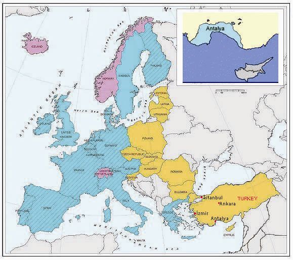
CONTENTS

1. INTRODUCTION
2. LINE SPECIFICATIONS
3. SPEED AND ROUND TRIP TIME
4. SERVICE HOURS AND FREQUENCY
5. GENERAL OPERATION OBJECTIVES AND SYSTEM REQUIREMENTS
6. VEHICLE CAPACITY
7. CAPACITY CALCULATIONS
8. STOP LOCATIONS AND DISTANCES
9. ELECTROMECHANICAL SYSTEMS
10. ELECTRIFACATION
11. CATENARY
12. VEHICLES
13. CLIMATIC CONDITIONS
14. NOISE LEVEL
15. SAFETY SYSTEMS
16. DEPOT AREA AND WORKSHOP BUILDING
17. FARE COLLECTION
16. SOIL INVESTIGATIONS
17. INFRASTRUCTURES
18. INVESTMENT TIMETABLE
19. ENVIROMENTAL IMPACTS OF THE PROJECT
20. CONCLUSION

                                  2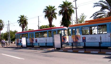
1. INTRODUCTION
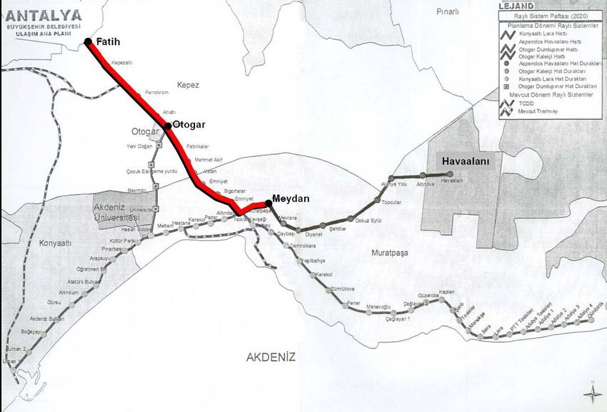
The purpose of this non technical summary report is to give an idea about Antalya 1st Stage Street
Tram Project in Turkey. The length of the 1st stage line between Fatih-Otogar (Intercity Bus
Terminal) and Meydan station is 11.13 km and alignment of the line is shown in Figure 2.
Figure 1. Location of Antalya city
2. LINE SPECIFICATIONS
The lines, introduced in the Antalya Transportation Master Plan (2005) as railway system corridors,
are shown below.
• Fatih – Otogar – Meydan Line – 1st Stage
• Otogar – Konyaaltı Line – 2nd Stage
• Konyaaltı – Lara Line – 3rd Stage
• Existing Tramway Line – 5 km
Fatih-Otogar-Meydan Street Tram Line is a double track tramway system having 16 stations and a
depot area, maintenance shops and yards. It is designed to satisfy passenger demands estimated
with Transportation Master Plan for year 2020.
3
The Street Tram Lines and peak-hour passenger demands in one direction, based on 2020 target
year, are listed below.

       a.) Kepez – Otogar – Airport Line    14,194 passengers/hour/direction
       b.) Otogar – Konyaaltı Line          12,543 passengers/hour/direction
       c.) Konyaaltı – Lara Line             8,035 passengers/hour/direction
       d.) Existing Tramway Line             7,561 passengers/hour/direction

Evaluation of these figures show that demand levels on Konyaaltı–Lara Line can be answered with
rubber tired public transport modes while passenger demands on the existing tramway line can be
satisfied by capacity expansions of the present system. This evaluation results with definition of two
corridors requiring rail system capacity by 2020 year with passenger demand levels.

The vehicle storage-maintenance-repair facility, also called as depot area, is located before the Fatih
stop on the opposite side of the Antalya Avenue. The dimensions and the geometry of the depot
area are determined to provide a capacity that shall cover not only the target year vehicle demand of
the proposed 1st Stage Railway System Line. Vehicle storage need resulting from the increase in
the total number of vehicles due to future extension of Antalya 1st Stage Railway System Line
towards Airport will be supplied by a vehicle storage facility to be designed at the end of the line.

           Figure 2. Location of Fatih- Meydan 1.Stage Street Tram Line Alignment

                                                  4
The proposed system has been planned to carry 7000 passengers per hour per direction with a
headway of 4.50 minutes for the year 2009, whereas in the year 2020, to reach a capacity of 12500
passengers per hour per direction with a headway of 2.50 minutes. A train used in the system
consists of either one or two vehicles with appropriate length of 42 m (maximum 45m). During
system operation, the maximum waiting time of a train is prescribed as 20 seconds. In the line
capacity calculations, peak-hour density of the standing passengers is estimated as 6
passengers/m2, provided that the full rate of the vehicles at peak hour is 95%.
3. SPEED AND ROUND TRIP TIME
Maximum theoretical operation speed on the main line is estimated as follow:
• Fatih – Otogar : 70km/hour
• Otogar – Muratpaşa : 50km/hour
• Muratpaşa – Doğu Garajı : 20km/hour
• Doğu Garajı – Meydan : 50km/hour
However, the design speed shall be reduced at those locations: vicinity of a stop, signalized highway
intersections, switches, narrow radius curves due to geometrical limitations, and programmed entry
and exit of the main line services. In the depot areas and storage facilities, the maximum operation
speed is planned as 20 km/hour. To calculate the commercial speed on a line, twice the distance
between two stops on that line is divided by the round trip time.
The definition of the round trip time is the duration needed for a vehicle departing from the start
point, heading towards the end of the line while stopping at all the intermediate points, after reaching
the destination making a trip back to the start point for a new trip. In the case of 1st Stage Street
Tram Line, the round trip time is the total time needed for a vehicle starting from Fatih stop, stopping
at all intermediate stops, reaching Meydan stop, returning to Fatih stop and reversing again to begin
a new trip from Fatih to Meydan. Departure Arrival Line Length between Fatih – Meydan is planned
as (2x11.13=) 22.26km. The commercial speed and the round trip time are calculated as 27 km/hour
and 48 minutes, respectively.
4. SERVICE HOURS AND FREQUENCY
The service schedule is given to derive a preliminary operating plan, annual car mileage, and
maintenance requirements. The actual operating plan will be prepared prior to start up operations
together with an integrated bus system operation plan.
• Minimum headway at peak hours shall;
Not shorter than 4.5 minutes for 2010 (14 trains per hour),
Not shorter than 2.5 minutes for 2020 (24 trains per hour).
• Maximum headway at off-peak hours shall;
not exceed 12 minutes for 2010 (5 trains per hour),
Not exceed 6 minutes for 2020 (10 trains per hour).
• Night service headway shall not exceed 12 minutes (5 trains per hour).
• For maintenance, the system will be shut down for 6 hours between 24:00-06:00.
5The schedule for weekday operations is as follows:
• Total operating day consists of 18 hours including start up and shut down between 06:00 and24:00.
• The morning peak service time is between 07:00 and 08:00.
• Off-peak service time is from 06:00 to 07:00 and from 08:00 to 17:00.
• The evening peak service time is between 17:00 and 20:00.
• The night service time is from 20:00 to 24:00.
5. GENERAL OPERATION OBJECTIVES AND SYSTEM REQUIREMENTS
In the design stage of the Antalya 1st Stage Railway System Line, all the determined operation
objectives and system supply necessities are intended tube covered. Therefore, it is crucial to have
good coordination between each component of the system and system as a whole. Moreover, in
order to provide system safety and service reliability in the most appropriate and economical way,
with the minimum operation-maintenance cost, superior system reliability, utility and reparability shall
be ensured.
6. VEHICLE CAPACITY
The vehicles shall conform to the capacity requirements shown on the table below. Not to limit the
vehicle alternatives, the vehicle length is selected as approximately 21 m. and 42 m. if a train
consists of single or double vehicles, respectively.
VEHICLE AND TRAINS
Vehicle Length (In a Double Vehicle Train) 21 m (Maximum 22,5m)
Vehicle Length (In a Single Vehicle Train) 42 m (Maximum 45m)
Vehicle Width 2.65 m
Number of Vehicles in a Train 2 2 (for 21m vehicle)
Number of Vehicles in a Train 1 1 (for 42m vehicle)
Maximum Speed 70 km/hour
Total Vehicle Passenger Capacity -6 pass./m2 275 (for 21m vehicle)
Total Vehicle Passenger Capacity -6 pass./m2 550 (for 42m vehicle)
Vehicle Average Acceleration 0.90 m/sec
Vehicle Average Deceleration 1.30 m/sec
Vehicle Traction Type Catenary (750 V DC)
Vehicle Capacities at Peak Hour 95%
67. CAPACITY CALCULATIONS
The properties of the Antalya 1st Stage Railway System is tabulated below :
TRACK AND RAIL
Track Type Two Tracks
Track Superstructure Type Direct Fixation (Partially) and Ballast (Partially)
Track Gauge 1435 mm
Rail Profile Direct Fixation RI 60 and Ballast S 49
Track Length 11, 1 km
PLATFORMS
Platform Length 45 m
Platform Height 26 cm
Platform Type Side
OPERATION ASSUMPTIONS
Average Standing Time at the Stations 20 sec
Maximum Operating Speed 20-50-70 km/hour
Number of Vehicles in a Train 1 (max. 45,0m), 2 (max. 22,5m)
Commercial Speed 27,00 km/hour
Minimum Operating Headway 270 sec
Vehicle Backup Ratio 10 %
Waiting Time 120 sec
Approximate Round Trip Time 48 min.
Average Standing Time at the Stations 20 sec
Maximum Operating Speed 20-50-70 km/hour
Number of Vehicles in a Train 1 (max. 45,0m), 2 (max. 22,5m)
Commercial Speed 27,00 km/hour
Minimum Operating Headway 150 sec
Vehicle Backup Ratio 10 %
Waiting Time 120 sec
Approximate Round Trip Time 48 min.
Vehicle Length Maximum 45,0 m (one vehicle), Maximum 22,5 m (two vehicles)
Vehicle Width 2,65 m
Maximum Speed 70 km/hour
Total Passenger Capacity per Vehicle - 6 pass./m2 550
Vehicle Average Acceleration 0,90 m/sec2
Vehicle Average Deceleration 1,30 m/sec2
Vehicle Traction Type Catenary (750 V DC)
Vehicle Capacity at Peak Hour 95 %
Beginning of the Line 0+000
Stop No: Stop Name Stop Type Station Km
1 Fatih at Grade 0+045,00
2 Kepezaltı at Grade 0+875,99
3 Ferrokrom at Grade 1+777,16
4 Ahatlı at Grade 2+469,66
5 Otogar at Grade 3+130,71
6 Makina Kimya at Grade 3+933,34
7 Dokuma at Grade 4+454,34
8 Vatan at Grade 5+366,48
9 Çallı at Grade 6+306,13
10 Sigorta at Grade 6+767,13
11 Emniyet at Grade 7+556,63
12 Muratpaşa at Grade 8+018,05
13 İsmetpaşa at Grade 8+491,55
14 Doğu Garajı at Grade 9+170,94
15 Burhanettin Onat at Grade 9+981,38
16 Meydan at Grade 10+924,27
End of the Line 11+098
78. STOP LOCATIONS AND DISTANCES
Maximum operating speed on the alignment is predicted as follows:
Location Distance Maximum Operating Speed
• Fatih – Otogar : 2.25km: 70km/hour
• Otogar – Muratpaşa : 3.75km: 50km/hour
• Muratpaşa – Doğu Garajı : 1.00km: 20km/hour
• Doğu Garajı – Meydan : 1.63km: 50km/hour
• Highway Cross. and Stops : 2.50km : 20km/hour
In this case, when the weighted average along the line is calculated, the maximum operating speed
becomes; LINE LENGTH: 11.13km: For an average maximum speed of 45km/hour
The following table summarizes the Round Trip time based on the average maximum speed, actual
values for system capacity calculations, system headway, and vehicle fleet requirements.
Commercial Speed : 27 km/h
Total Round Trip Time : 48 min
Total Passenger Capacity per Vehicle : 550 pass.
Full Rate : 95%
Vehicle maintenance-repair and backup Ratio : 10%
2010 year Max. Ridership : 7000 pass./hour
2010 year theoretical headway : 4,48 min
2010 year practical headway : 4,5 min
2010 year number of vehicles in the fleet : 11 vehicles
2020 year Max. Ridership : 12500 pass./hour
2020 year theoretical headway : 2,51 min
2020 year practical headway : 2,5 min
2020 year number of vehicles in the fleet : 21 vehicles
Due to the fact that the alignment is positioned at the highway centre refuge axis, all the stops are
designed with side platforms. However, the platforms are placed either symmetrically or
asymmetrically depending on the location properties of the stops. Antalya 1st Stage Railway System
line begins with a loop track located prior to the Fatih stop at the east side refuge area of the Antalya
Avenue. After the loop track, the route reaches the Fatih stop, which consists of symmetrically
positioned platforms. Fatih stop area is planned as a transfer
9. ELECTROMECHANICAL SYSTEMS
In scope of electromechanical systems the systems listed below will take part.
• Electrification
• Signalling
• Control and Communication
• Fare collection
• Catenary
810. ELECTRIFACATION
System reliability and operation availability will be provided by supplying the line on both ends from
the TEIAS power distribution network at 34.5 kV level. The system power requirement for train
operation with 150 sec. (2.5 min.). Headway is calculated as 14.5 MW on the preliminary load study.
Following the meetings with Akdeniz Power Distribution Company it is agreed that the power
requirement of the system will be provided from the TEIAS 154/34,5 kV Varsak Transformer
Substation. For power transmission to the both ends of the LRT line, it is planned to install
underground cables from Varsak Transformer Substation. Power supply system for traction and
auxiliary power requirements is designed to operate as two radial lines supplied from both ends
providing operation alternatives. Power supply system design is considered on;
• 34,5 kV, for traction power substation and depot/workshop auxiliary power supply,
• 750V DC for LRT line traction power distribution,
• 400/230V for L.V. distribution,
• 220V - 110V DC for control circuits, levels.
Power supply system, will transform, convert and distribute the power provided from the power
distribution company to the LRT system. The traction network distributes the traction at nominal 750
V DC, which is fed to the running vehicles via the overhead line system and transmitted to the
vehicles by means of pantographs. The running rails will provide the return path for the current to the
negative DC bus of the traction power substation. Auxiliary AC power will supply lighting, HVAC,
electrical machinery, equipment, control circuits in traction power substations and depot/workshop.
Auxiliary power to the train stops located close to the traction power substation will be provided from
the traction power substation L.V. busbars, to the others from the local distribution or transformer
substations of AEDAS (Local Distribution Company). An essential complementary system to achieve
high availability of the power supply system is the computerized SCADA system, which is designed
for remote control and supervision of the power supply system.
11. CATENARY
The purpose of overhead line system (Catenary system) is to transfer 750 V DA from substation
buildings to pantograph of vehicles. The primary pieces of catenary system is contact wires,
messenger wires, hanger pieces, hanger devices, separators, track isolators and tensioning tools.
Main track will be designed as one contact wire and two messenger wires and in order to hold the
contact wire parallel to the track, it will be hanged up by hanger droppers. Catenary system in depot
will be designed as contact wire supported by a cable.
12. VEHICLES
In determination of dimensions of vehicles that shall be used at railway system, it is aimed to suit the
estimated number of passengers and the passenger carrying capacity of vehicle. After researches,
estimated passenger carrying capacity shall be reached by operation of vehicles with a width of 2.65
m and by train with single vehicle with a length of 42 m (maximum 45 m) or train with double
vehicles (EMU) with a length of 21 m (maximum 22.5 m). In order to increase the competition
conditions and to buy the most suitable priced vehicle, train with single vehicle (maximum 45 m) and
train with double vehicle (maximum 22.5m x 2 = 45m) are given as alternatives of vehicles. In order
to operate the railway system with a principle of 20 sec. standstill at intermediate stops, enough
number and wideness of doors shall be provided. When boarding/alighting numbers examined in
respect of year 2020 which is the target year on Transportation Main Plan, it is seen that the
9maximum boarding/alighting number is at Muratpaşa stop based on intermediate stops. At this stop,
at peak time totally 4182 person is passing through the doors of the railway system vehicles. When
2.5 minutes of headway is taken into account, train with one vehicle with a length of 42m (maximum
45m) or train with two vehicles with a length of 21m (maximum 22,5m), it is planned to find the width
and number of door which shall provide the required capacity in 20 sec standstill time at stop
including peak time factor with a totally 225 passenger boarding/alighting circulation.
13. CLIMATIC CONDITIONS
Vehicles shall be designed suitable to climatic conditions of Antalya, between -10°C and +45°C
atmospheric heat, 70% average moisture level, 100% maximum moisture level and 140 km/hr wind
velocity.
14. NOISE LEVEL
0.9 m away from the side walls, noise level in vehicle shall not exceed 70dB(A) when doors and
windows are closed during standstill and all auxiliary equipments except HVAC are working, 80dB(A)
when moving with a speed of70km/hr with a AW3 passenger load and all auxiliary equipments
except HVAC are working.
15. SAFETY SYSTEMS
Safety systems are described in three headings as driver safety, passenger safety and fire
protection. Driver security shall be provided by deadman system. By pressing a pedal or button,
driver will start the driving process. The button is preferred to be combined with traction/break arm.
In case of death or loose consciousness of driver, by releasing the button vehicle will start to
breaking. In order to shorten the breaking distance sand shall be sprayed between wheel and rail
automatically. Emergency break shall exist in passenger division. Emergency break arms shall be
placed at appropriate places in passenger division. In case of emergency situation in passenger
division, emergency break arm shall be pulled by passengers and vehicle will start breaking. In this
system, in order to shorten the breaking distance sand shall be sprayed between wheel and rail
automatically. For fire protection, all materials used in vehicle shall be resistant to fire and shall not
produce toxic gases. Materials shall be adequate to NFPA specification. As Antalya face with sea
climate, used materials shall be resistant to corrosion. While dimensioning the roof isolators, weather
conditions shall be taken into account.
16. DEPOT AREA AND WORKSHOP BUILDING
All the required operating process for the railway system will be done in the depot and workshop
facilities. The design of the railway system in the depot area can accommodate initially a fleet of 11
vehicles. However, considering the fact that the vehicles of the second Stage railway system in the
Fatih-Otogar-Adliye-Liman line will use the same depot area, general location plan enables to
enlarge the capacity up to 40 vehicles. In an extreme situation, total parking capacity can reach
approximately 50 vehicles provided that the tracks in and around the workshop, car wash, and
vehicle bottom wash buildings are used. Between the tracks, adequate area is left for vehicle
monitoring and field cleaning. Departure and arrival of the vehicles to the depot, workshop, and
washing buildings are designed to be performed with the least manoeuvre possible while not
impeding other manoeuvres in the vicinity. In the depot area, a circular track is formed to provide
effective use of railway track without influencing the main feeding tracks. The duties around the
10parking tracks will contain only the driver entrance and exit to the driver’s cabinet and safety checks
in daily basis prior to service. Service tracks are designed to perform these duties adequately.
Parking tracks are planned such that an electricity blackout will cause only limited effect on the
vehicle movement in the area. Safety and trespasser prevention will be provided by a guarding fence
around the perimeter of the depot area. Moreover, a guard house is added at the entrance of the
area. Buildings and facilities in the depot area are described in the following sections.
17. FARE COLLECTION
The Antalya mass transportation electronic ticket system is considered as a kind of electronic fare
collection system, which enables effective operation of urban mass transportation within the
municipality zone (various bus and railway system services) and have the passengers benefiting
from the transfer discounts with one ticket between the services and operators. The anticipated
system for Antalya railway system will be initially used within the railway system. However, in the
future, it will also be used to collect fares of the other operating public mass transportation systems
(municipality and private buses). In addition to this, if desired, this system would provide electronic
payment processes with widespread use of the payments for car parking fares. Passengers will
enter to the platforms after passing the turnstiles at the platform entrance, which separate controlled
and free zones. At the stops, it is expected that the passengers coming to the platforms disorderly
between the headways will use the turnstiles, whereas the passengers getting out of the railway
system vehicle will immediately leave the platforms by passing the winged doors. The mentioned
winged doors will enable the disabled passengers with wheeled chair to reach the platforms.
16. SOIL INVESTIGATIONS
The soil profile in the project area basically consists of travertine unit overlain by the made ground
with varying thickness. This formation is brown, thin to moderately bedded, locally massive and
thickly bedded with frequent solution cavities and spongy texture. 37 boreholes were executed long
the route and at the depot site in order to identify the lithological, physical and mechanical
properties, boundaries, extensions, thickness of soil and rock units and to determine the
groundwater level.
17. INFRASTRUCTURES
At infrastructure designation works, existing and planned potable water, wastewater, rainwater,
telecommunication and power lines are planned to determine the location from documentation taken
from related organization and in-situ observations in the alignment corridor. In case of coinciding of
existing infrastructure network that is obtained from infrastructure designation works with railway
system line and structures, firstly infrastructures locations shall be preserved and produce general
and local solutions by additional structures when needed. Infrastructure system which is coinciding
with railway system line and structures and must relocated, is planned to be permanently or
temporarily relocated according to related organization suggestions, directives and approvals.
Infrastructure lines which are planned to be permanently relocated will be replaced to its original
place at the end of construction. Also it is planned to examine current infrastructure lines and take
precautions against any damage on the railway system when a failure take place. While planning the
relocation of infrastructures, related organization’s standards are used. By this it is planned to
control, care and repair the infrastructure lines without any interruption at operation of railway
system.
1118. INVESTMENT TIMETABLE
Antalya 1. Stage Railway system is expected to be completed in 2008 and first half of 2009 and
taken into operation in 2009.
19. ENVIROMENTAL IMPACTS OF THE PROJECT
19.1. Utilization of Natural Resources (Land Use, Water Use, Energy Use, etc.)
Land Use: Because the system is designed as a street tramway and the highway traffic is running
parallel to the railway system, right or left turns on the highway can cause severe risk on the railway
operation safety. Therefore, the railway system is planned to run on the centre refuge axis between
Otogar and Meydan stops and on the right side refuge with respect to the route direction (north east
direction) with a width in the range of 10-15 m between Fatih and Otogar stops. The fill and cut
facilities performed during the construction phase of the railway system project, which was designed
within the existing road corridor, will generally be composed of levelling and grading works. The
excavations that may be generated from these types of Works shall be disposed according to the
rules and regulations of the “Excavation Soil, Construction and Debris Waste Control Regulation
(18.03.2004 dated and 25406 numbered Official Gazette).
Water Use; Water will only be used for drinking and service water purposes by the personnel who
will be working during the construction phase. During the construction phase, a team of 300 capita
will be employed. The daily water demand is calculated as 45 m3/day with the assumption of a
150L/day water consumption per capita. The water will be supplied from the water network of the
municipality or will be brought by water tanks.
Energy Use: For the construction phase, energy demand will be supplied from the network of the
municipality or by a generator.
Other: The alignment was designed within the existing road corridor. Therefore, during the
construction phase, only discrete number of trees can be moved from the refuge. There are no other
issues to mention in this section.
19.2. Waste Production Quantity (solid, liquid, gas, etc) and Chemical, Physical and
Biological Characteristics of the Wastes
19.2.1. Characteristics, Quantity and Disposal Methods of the Solid Wastes Generated
During the Construction and Operational Phases
Construction Phase: During the construction phase, inorganic demolition wastes and domestic
solid wastes will be generated. The hut at the construction site will be placed at a central location
which has infrastructure means and logistics support. The number of personnel is planned to be 300
capita. According to the 2002 Municipality Solid Waste Results published by the State Institute of
Statistics (SIS) on date of 28.12.2004, the quantity of annual average solid waste produced per
capita is specified 1.34 kg/day, in Turkey. Quantity of domestic solid waste production rate in the
construction site will probably be less than the above stated value, but in order to evaluate the worst
conditions, that value was used to calculate the solid waste quantity. The amount of domestic solid
waste was calculated as: 300 capita x 1.34 kg/capita/day = 402 kg. The solid wastes generated
within the construction site shall be stored in the waste containers and shall be collected by the
Municipality. Collection, storage, recycling and disposal of these solid wastes shall be carried out
12according to the Solid Waste Control Regulation (14.03.1991 dated and 20814 numbered Official
Gazette). The fill and cut facilities performed during the construction phase of the railway system
project will generally be composed of levelling and grading works. The excavated soil that may be
generated from these types of works shall be disposed according to the rules and regulations of the
“Excavation Soil, Construction and Debris Waste Control Regulation (18.03.2004 dated and 25406
numbered Official Gazette). No types of hazardous wastes, defined as per the hazardous Wastes
Control Regulation (27.08.1995 dated and 22387 numbered Official Gazette), will be generated
during the construction phase. The rules and regulations of the Waste Oil Control Regulation
(21.01.2004 dated and 25353 numbered Official Gazette) will be carried out related with the waste
oils generated from the construction vehicles. All the above specified laws and regulations shall be
complied for the quarries to be utilized for material supply for the construction of the Railway
System.
Operational Phase: The solid waste that is expected to be generated during the operational phase
will consist of wastes from the maintenance and repair activities of the railway line and the domestic
waste from the activities of the personnel. The wastes to be generated and information about them
was listed below, and these wastes shall be disposed according to the rules and regulations of the
“Excavation Soil, Construction and Debris Waste Control Regulation (18.03.2004 dated and 25406
numbered Official Gazette):
Ballast screening: It is estimated that 0, 1 m³ waste will be produced per 1 meter of screened ballast.
This ballast screening is performed every five years. Superstructure replacement: Superstructure
replacement facilities were performed every 30 years and the waste generated is concrete sleepers.
Infrastructure replacement: The waste generated due to the infrastructure replacement facilities is
rail. The domestic solid waste amount produced during the operational phase was calculated as; 246
capita x 1.34 kg/capita/day = 330 kg. The solid wastes shall be stored in the waste containers and
shall be collected by the Municipality. Collection, storage, recycling and disposal of these solid
wastes shall be carried out according to the Solid Waste Control Regulation (14.03.1991 dated and
20814 numbered Official Gazette). No types of solid wastes will be produced during the trip of the
tramway. The package and other similar wastes to be generated at the stops shall be stored in the
garbage containers and collected by the Municipality. Collection, storage, recycling and disposal of
these solid wastes shall be carried out according to the Package and Package Wastes Control
Regulation (published on 30.07.2004 dated and 25538 numbered Official Gazette and become valid
since 01.01.2005).
A hazardous waste storage building was designed to store the hazardous and explosive wastes like
paint, solvent, oil, etc which may be generated during the operational phase. This structure will be a
simple shed type and shall be fenced and locked. It is located to be easily accessible from the road
in the storage area and far away from the other main buildings. The hazardous and explosive wastes
generated during the operational phase will be stored in this “Hazardous Waste Storage” building
and the requirements will be fulfilled according to the Hazardous Waste Control Regulation
(27.08.1995 dated and 22387 numbered Official Gazette).
19.2.2. Characteristics, Quantity and Disposal Methods of the Liquid Wastes
Generated During the Construction and Operational Phases
Construction Phase: There will not be any industrial waste water generation during the
construction phase as the water will only be used for concrete preparation and this water will
completely be hold within the material. There will be domestic waste water generating according to
the personnel working in the site during the construction phase. The number of personnel will be 300
capita and therefore the volume of waste water produced is calculated as 45 m3 based on the
13assumptions of 150 L/day/capita water consumption, all of this water utilized will become waste
water, and all of the personnel will accommodate in the construction site. The water usage and
therefore waste water generation volumes will be much less than the above stated values as the
personnel employed in the site will be from the vicinity. The hut at the construction site will be placed
at a central location which has infrastructure means and logistics support. Under the condition that
the waste water lines from the hut cannot be connected to the network of the municipality, then an
impermeable type septic tank shall be constructed and the waste water from the septic tank shall be
collected and disposed to the specified locations by the sewage trucks of the Municipality. The septic
tank shall conform to the rules specified in the Regulation Concerning Septic Tanks in Areas Where
Sewer Channels cannot be Constructed (13.03.1971 dated and 13783 numbered Official Gazette).
During construction phase, there will be no need for dust creating processes such as pleating and
grinding. Besides, sand and gravel will not be stored on site in excessive amounts. Necessary
amounts will be transferred to the site as needed. For this reason, no designated storage area is
required on the site and there will not be any dust emissions due to storage. Transportation of
construction material may generate insignificant amounts of dust. Cement will be stored in special
bags in order to prevent dust creation. The construction and excavation material which may be
potential sources of dust emissions will be carried mainly by trucks. The trucks will be covered in
order to prevent the dispersion of the particulate matter. All vehicles will comply with the relevant
speed limits and the truck drivers will pay utmost attention while using stabilized roads and/or
temporary roads. In order to decrease dust emissions, necessary mitigation measures will be
complied with (e.g., application of water spraying where necessary). It is not expected any dust
emissions during the operational phase of the Railway System.
19.3. Environmental Noise Generated During the Construction and Operational
Phases and Preventive Measures
Construction Phase: Construction of the proposed railway will include the following noise-
generating activities; utilization of the construction equipment and machinery during excavation,
utilization of the construction vehicles for transport and utilization of site vehicles. The Leq values of
construction machinery are defined in the Regulation on Environmental Noise Levels of the
Construction Machinery (published in the Official Gazette dated January 1, 2003 and numbered
25001). Noise levels versus distances are calculated using Leq values. In the calculations, the
numbers of machinery that will be used at the same time are considered.
Operational Phase: In Article 22 of the RENAM, provisions in which railway vehicles have to obey
are stated. According to this, the health of the passengers and workers and the level that needs to
be set are given to the responsibility of he Ministry of Transportation. Article 22 of the RENAM is
provided below:
For the settlements not to be effected by the railway activities the following measures shall be taken
where there exist 30.000 train traffic annually, and the population density, area characteristics and
number of complaints shall be taken into consideration;
1. Noise measurements for all the vehicles shall be implemented,
2. Silencers shall be employed at the trains for noise control,
3. Composite material breaks shall be utilized instead of cast iron,
4. Disc type breaks shall be utilized,
5. Necessary measures shall be taken regarding the structure of the machine,
6. The wheels of the wagons and locomotive shall be smoothed, greased, and other preventive
measures shall be taken,
147. The tracks shall be periodically rehabilitated, plastic wedges shall be utilized, rails shall be
welded, appropriate curves shall be employed, the shoulders shall be covered with sound proof
materials, the elevation of the railway shall be arranged according to the environment,
8. Application of appropriate sound insulation measures at the problematic areas, according to the
related ISO and TSE standards and insulation calculations.
9. To employ effective and applicable techniques for noise screening measures in accordance with
the TSE Standards at the banks of the roads.
Regulation on Environmental Noise Assessment and Management shall be assured within the scope
of the project. Additionally, the contingency planning for emergencies shall be carried out as stated
below:
Vehicles and equipments for emergencies shall be identified and kept at a separate place. Among
these equipments, pickaxe and shovels, head masks, protective goggles, gloves, various pumps,
non-explosive electric pumps, radios and similar equipments shall be found.
The intervention of the heavy vehicles shall be planned prior and the parking arrangements of
these shall be done accordingly.
Emergency Action Plan shall consist of lists of the emergency teams, locations of the safety
equipments and vehicles, emergency exit and related procedures. Furthermore, the emergency
contact numbers shall also be within this plan.
Emergency Action plan shall continuously revise and the inspection and maintenance of all the
related equipments shall be performed periodically. The key personnel shall be trained in these
matters.
The nearest security unit (police or gendarme) and fire brigade unit shall immediately be notified.
19.4. Precautions to be Taken Against the Possible Environmental Impacts of the
Project
In order to mitigate the negative impacts of the railway system on the environment, the measures to
be taken were listed below:
Periodic measurement of the exhaust emissions of the construction vehicles and
rehabilitation/renewal of these vehicles shall be done when necessary.
In order the noise generated during the construction phase not to impact the environment
unfavourably, the working hours shall be imitated to the daytime.
Personal protective equipments (like helmets, earflaps, etc) shall be provided for the workers and
all the necessary precautions shall be taken in accordance with the Article 22 of Regulation on
Occupational Health and Safety (published in the Official Gazette dated 11.01.1974 and numbered
14765).
Periodic noise measurements shall be performed in order to determine the generated noise levels.
The periodic maintenance of the vehicles shall be performed and it shall be assured that the limit
values of the emissions and noise as per related regulations are never exceeded.
Waste waters shall be collected in the septic tanks if necessary. These septic tanks at the
construction sites shall be in accordance with the Regulation Concerning Septic Tanks in Areas
Where Sewer Channels Cannot be Constructed (13.03.1971 dated and 13783 numbered Official
Gazette).
1519.4.1. Land Usage and Quality (Agricultural Area, Forestry Area, Planned Area,
Water Surface, etc.)
Alignment is located along Kepez (Fatih) – Otogar – Meydan corridor and the entire alignment is
designed as street tramway at grade. Alignment does not pass through any agricultural area,
forestry area or water surface.
19.4.2. Planned Areas, Urban Design Arrangements
While designing the alignment route and determining the locations of the railway stops, existing
transportation routes and new projects and arrangements are taken into consideration. These
projects include the urban design projects and highway arrangements realized by the Greater
Municipality of Antalya, plus the highway intersection planning realized by General Directorate of
Highways. These plans and projects are listed below:
Kepez entrance cloverleaf junction planning
Kale Kapısı Section Ali Cetinkaya Street pedestrian region planning
Ali Cetinkaya Street Sobacılar Bazaar project
Ali Cetinkaya Street Convention Center project
Meydan Junction highway arrangement
Eski Meydan Junction highway arrangement
It is intended that the railway system line and stops will be in accordance with other urban design
projects, which will take place in near future.
19.4.3. Existing Infrastructures
At infrastructure designation works, existing and planned potable water, wastewater, rainwater,
telecommunication and power lines have been planned to determine the location from
documentation taken from related organization and in-situ observations in the alignment corridor. In
case of coinciding of existing infrastructure network that is obtained from infrastructure designation
works with railway system line and structures, firstly infrastructures locations shall be preserved and
produce general and local solutions by additional structures when needed. Infrastructure system
which is coinciding with railway system line and structures and must relocated, is planned to be
permanently or temporarily relocated according to related organization suggestions, directives and
approvals. Infrastructure lines which are planned to be permanently relocated will be replaced to its
original place at the end of construction. Also it is planned to examine current infrastructure lines and
take precautions against any damage on the railway system when a failure take place. While
planning the relocation of infrastructures, related organization’s standards are used. By this it is
planned to control, care and repair the infrastructure lines without any interruption at operation of
railway system.
20. CONCLUSION
Antalya 1st Stage Railway System Line is consisted of the 11.13 km long Kepez (Fatih)– Otogar –
Meydan portion of the Kepez – Otogar – Airport railway line of the Antalya Transportation Master
Plan. System will connect the North corridor of the city to the City Centre. Extensive evaluation of the
alignment alternatives, including the subjects such as passenger demands, ease of access for the
passengers to the railway system or other means of transportation, reaching high operating speeds,
the use of land in the most economical way, etc., reached the conclusion of selecting the most
feasible alignment.
16Benefits of the project are; reduction in accidents, travel time savings, decrease in fuel consumption,
highway maintenance and repair cost savings, reduction in air pollution and noise level.
Implementation of the project results with reduction in urban highway passenger (and vehicle)
kilometres and increase in rail passenger kilometres. This effect of the project diverting trips from
highway modes to rail systems results with reduction in accidents. Additionally, implementation of
the Project create reductions in travel times thus time savings. Usage of private transportation
vehicles (automobile), as well as rubber tired public transport modes (buses) will decline with
implementation of the rail project. Increase of passengers and passenger kilometres on the rail
system causes decrease in fuel consumption of motorized highway vehicles. Travel demands on
highway network will decline as a result of rail system operations which will create savings from the
reduced construction costs for new roads and existing road expansions otherwise without the rail
system would be needed. Reductions of trips and passenger kilometres on the urban highway
system, as a result of the urban rail services create highway maintenance and repair cost savings.
The project will help to achieve improved utilization of Antalya’s insufficient transport infrastructure,
reduce pressures for converting urban land to roads, junctions and car parks, support urban
development along the objectives and strategies of land use and development master plan.
Decreasing highway vehicle kilometres as a result of the rail system operation lead to significant
reductions of transport related air pollution. Reduction in highway traffic volumes will also help to
decrease transport related noise levels in the city. Increased number of trains due to higher rail
transit service levels will result with higher noise levels in the rail corridor, but these increases will be
negligible compared to overall noise reductions in the general urban environment.
Railway system alignment has been designed on the existing road route. Through the alignment,
there is not any Wetlands, Coasts, Mountainous and Forestry Areas, Agricultural Areas, National
Parks, Special Protection Areas, Densely Populated Areas, Historical, Cultural, Archaeological and
Other Similar Areas, Erosion Areas, Landslide Areas, Afforestated Areas, Potential Areas for
Erosion and Afforestation and Aquifers to be Protected as per 167 numbered Under Ground Waters
Law.
17You can also read