ISTANBUL TECHNICAL UNIVERSITY ROBOSUB 2021 TECHNICAL DESIGN REPORT - ROBONATION
←
→
Page content transcription
If your browser does not render page correctly, please read the page content below
Istanbul Technical University RoboSub 2021
                    Technical Design Report
S. Yazici, T. Arslan, Z. Uyar, I. Bahadir, I. Sarac, E. Kartal, M. T. Ozdenoglu, E. Cirakman, A. E. Karadag,
                               C. R. Yildizay, S. C. Kirgoz, Y. Polat, D. S. Bal

   Abstract—The vehicle named Turquoise, which we designed           minimal during the design and development process due
as ITU AUV Team, has emerged as a result of long studies             to the limited time.
because of both financial inadequacy and lack of knowledge.
Our vehicle, which could not participate in the RoboSub 2020
due to cancellation of the physical competition, gained a new          A camera was placed facing downward to detect path
look with the changes we made this year. Mechanical studies          markers to localize the next mission. The detection is
focused on reducing vehicle weight and increasing the strength       performed with OpenCV by applying an image color
of the vehicle. In electrical studies, previously designed cards     restoring method, color filtering, thresholding and contour
have been improved and focused on the operation of the               detection. This enables the vehicle to obtain a head-
vehicle for a longer period of time. In software studies, previous
software were improved and restructured for better debugging         ing angle to the mission. To save weight and prevent
and portability as well as efficiency.                               complexity, a Raspberry Pi camera used because of its
                                                                     dimensions, which enabled us to place the camera in the
                   I. Competition Strategy                           watertight enclosure. However, this required extra camera
                                                                     calibrations, as the image is lensed through the acrylic
   Although there are frequent restrictions in Turkey, due
                                                                     enclosure. Considering the fact that outside placement re-
to the coronavirus, team members have tried to continue
                                                                     quired an extra watertight enclosure, our team has decided
their preparations for the competition with social media
                                                                     machining such parts would take more effort compared to
platform such as Discord and Zoom. The Hull Design video
                                                                     solving this problem by using camera calibration with a
was specially shot within the scope of the permissions
                                                                     camera placed inside the main enclosure.
obtained from ITU. Since the limitations within the scope
of the competition were not clearly evident, the tasks given
                                                                       For the Make The Grade mission, a forward looking
were made according to the limitations of the previous
                                                                     camera is used with our trained YOLO model for a tommy
period.
                                                                     gun and a badge. Similar Guidance & Navigation methods
   Team members accomplished the tasks given below and
                                                                     were performed for this mission, enabling the vehicle to
took their videos.
                                                                     complete the mission without extra tools & steps. Due to
   • Start Gate                                                      lower complexity on this mission, our team implemented
   • Path                                                            the Choose Your Side functionality, and thus enabled the
   • Make The Grade                                                  vehicle to aim for the correct target and hit it.
   • Collecting
   • Survive The Shootout                                              Considering the requirements of the Collecting mission
   • Cash or Smash                                                   for full points award, our team has decided to not to lift
   The team plans on completing the start gate mission               the cover, therefore focus on dropping to the appropriate
without penalty. To accomplish this task, a vehicle with             section. Again, similar algorithms were used with the
appropriate dimensions is important. Our team paid                   bottom camera. Instead of lifting the cover, our team will
attention to these details on the process of hull design.            use their effort and this competition time, for the Survive
The box shaped frame design enables to use of the volume             The Shootout mission, and therefore has spent efforts on
effectively. Our team kept in mind that any parts or                 developing acoustic signal processing system and torpedo
tools places outside of the box shaped frame, might cause            launch system.
problems in the start gate mission as those parts might
hit the gate. Also, this provides a safe enclosure for all              A torpedo launch system is designed with low complex-
actuators and sensors such as DVL, just in case. To                  ity design ideas. Our team have had different approaches
perform a barrel roll for stylish movement and extra                 for launch system before, using electromagnetic forces.
points, the difference of center of buoyancy and center of           But due to complexity of electromagnetic launch system,
mass needed to be reduced in order to reduce the required            and also after inspecting many other teams’ reports
torque while rolling. This required some modifications on            and designs, our team has concluded on the pressurized
the vehicle, and therefore some effort. These efforts kept           pneumatic launch system for this mission.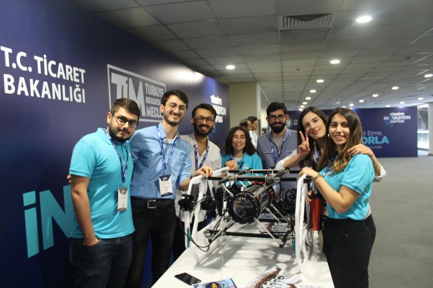
Istanbul Technical University Autonomous Underwater Vehicle

                   II. Design Creativity                              big aluminium cylinder bought and manufactured on
A. Mechanical                                                         a CNC machine. Thanks to aluminium the bulkhead
                                                                      is lighter than it seems.
   Our vehicle is 764mm long and 616mm wide and consists
of three parts; tubes, bulkhead and chasis. Each part
carries different kind of materials and equipments. To
make our vehicle lighter, covers are emptied by carving
in every suitable place and the bulkhead is largely empty
from the inside.

                                                                                Fig. 3. Bulkhead Between Tubes

                                                                  •   Chasis: Every part of the vehicle is somehow con-
                                                                      nected to chasis. Chasis is the skeleton of the system.
                                                                      What makes chasis a thing is sigma profiles. Sigma
                                                                      profiles are connecting each other and together they
                                                                      make the chasis. Sigma profiles are very light and
           Fig. 1. Turquoise From Upper Front View
                                                                      strong enough to carry more than AUV needs. Also,
                                                                      their shape makes us to use them as puzzle and
  •   Tubes: The tubes acrylic cylinders and are used for             assemble anything on them with little effort.
      covering our electronics completely. Each tube has a
      diameter of 172mm and are 298mm long. Tubes are             1) Mission Tools:
      connected to the bulkheads flanges with o-rings and         •   Marker Dropper: Marker dropper is a tool for launch-
      make electronics completely safe from water.                    ing markers out of AUV. It works with gravity and
                                                                      a solenoid valve. Markers are conserved in droppers
                                                                      holding and when solenoid activated markers fall off
                                                                      themselves.

        Fig. 2. One Of The Tubes With Electronics In It

  •   Bulkhead: The bulkhead is made of aluminium and
      in the shape of an octagonal cylinder. Four faces
      of the bulkhead have penetrator holes for letting
      cables in and out. Each of these four faces has 8
      holes and enables 32 entries in total. Bulkhead has
      openings on two sides and these openings are covered
      with flange. There are o-ring seats on these flanges,                   Fig. 4. One Of The Marker Droppers
      which makes our vehicle waterproof when tubes are
      connected to flanges and compressing o-rings. It was        •   Torpedo Launcher: To launch our torpedo we have a
      essential to making bulkhead one solid material so a            pneumatic system. Launcher is located in the front of

                                                              2
Istanbul Technical University Autonomous Underwater Vehicle

      the vehicle and looking forwards. When compressed            batteries. Each battery have an average voltage of 3.6V
      air pushes the piston torpedo launches off.                  and a capacity of 3000mAh. The configuration of these
                                                                   batteries is 4S9P (4 series 9 parallel) and a total of 36
                                                                   cells battery pack has 26100mAh capacity, 14.4V voltage
                                                                   and 375Wh energy. Considering the power requirement of
                                                                   the vehicle’s eight engines and other electronic circuits, an
                                                                   11AWG cable is used to satisfy the power consumption of
                                                                   approximately 20W in stagnant operation, approximately
                                                                   70-80W in continuous operation and up to 500W in instant
                                                                   operation.For an average power consumption of 80W in
                                                                   continuous operation, this battery pack runs the vehicle
                                                                   for approximately 210 minutes (3.5 hours).

                    Fig. 5. Torpedo Launcher

  •   Manipulator: Our manipulator is also works with
      pneumatic system and located in the front of the
      vehicle as well. It’s working principle with torpedo
      launcher is substantially same.

                                                                                 Fig. 7. Power Distribution Diagram

                                                                      A Battery Management System (BMS) circuit in the
                                                                   battery pack ensures the charging safety of lithium-ion
                                                                   batteries, and a temperature sensor on this circuit provides
                                                                   security against heating problems. Moreover, the power
                                                                   inputs taken from the battery pack are protected against
                                                                   possible short circuits and overcurrents with the help of
                                                                   fuses on the PCB’s.
                                                                        b) Sensors: An Inertial Measurement Unit 1 (IMU)
                Fig. 6. Pneumatic System Diagram                   is used to determine angle of rotation, rate of rotation and
                                                                   linear acceleration.The selected inertia measurement unit
B. Electrical                                                      is shown in Figure 8.
   The design of the electrical system aims to be both
supervised and allowed the microprocessors to communi-
cate with the various sensors and motors on the vehicle,
furthermore be regulated the power distribution within
the vehicle.
     a) Power Distribution: Components in the vehicle
can operate with input power at different voltages. There-               Fig. 8. XSens Mti-G-710 Inertia Measurement Unit
fore , a power distribution system was created. There is a
high power requirement in the AUV because the underwa-                It was decided to use the pressure sensor 2 , considering
ter vehicles must have high mobility. For this , the vehicle       its small dimensions and high sensitivity in order to
is powered by a battery pack which specially designed               1 shop.xsens.com

by team members. This battery pack contains lithium-ion             2 bluerobotics.com

                                                               3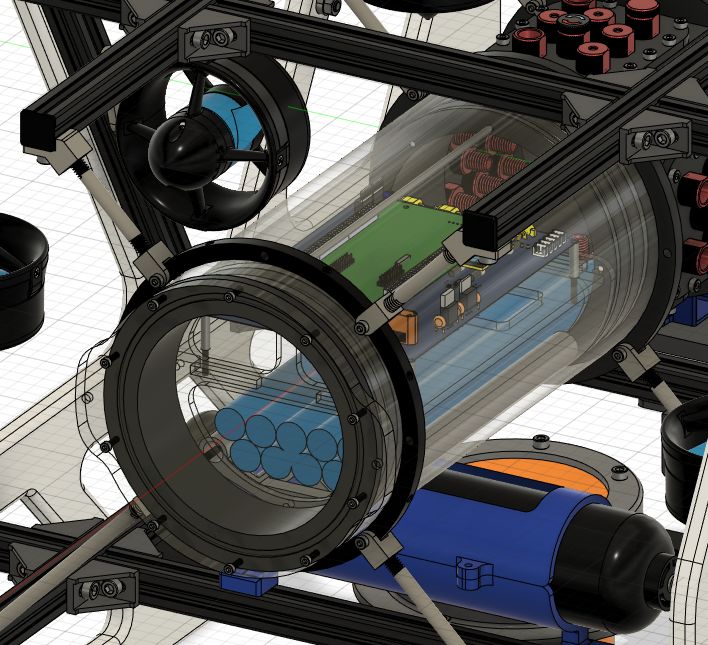
Istanbul Technical University Autonomous Underwater Vehicle

stabilize the depth of the vehicle during the missions. Even              c) Motherboard: To operate all actuators and obtain
though the depth can be measured with the help of the                data from all sensors, a motherboard is designed. The
pressure sensor, the mission might fail if the altitude of the       motherboard consists of 8 Electronic Speed Controllers
vehicle (distance to the ground) is not measured precisely.          (ESC), the power distribution infrastructure, STM32F4
In this context, due to its cost and small volume, 2 Ping            type microcontroller and multiple connectors for sensor
Sonar 3 were used and the distance to the ground could               connections. Also, a current sensor is placed on the power
be determined horizontally and vertically. It is important           line of each ESC to obtain the current draw of each
to know the location of the vehicle during the execution             thruster. This enables the microcontroller to estimate
of the tasks. A Doppler Velocity Log 4 (DVL), which has              the thrust or to implement some safety features. The
a high operating frequency range and complies with the               motherboard has been designed to reduce the complexity
weight and size restrictions of the competition, was used            of cables by aiming for ease of use. There are 8 Electronic
in order to determine the position of the vehicle relative           Speed Controllers (ESC) on the motherboard, 4 of which
to the (x, y) axes. The selected DVL is shown in Figure              are on the bottom layer of the board where the vehicle’s
9.                                                                   engines are controlled and 4 are on the top layer of the
                                                                     board. ESCs are mounted in their designated places on
                                                                     the motherboard and the connecting cables are shortened
                                                                     as much as possible, thus avoiding cable clutter and saving
                                                                     space. There is a microcontroller from the STM32F4
                                                                     family on the board. It is connected to the relevant
                                                                     headers from the selected communication pins of this
                                                                     microcontroller. Communication with the sensors to be
                                                                     used is provided through these headers.

                Fig. 9. Navquest 600 Micro DVL

3 hydrophones will be used for the acoustic detection of
the signal emitting pinger. A hydrophone is an underwater
microphone obtained by covering a piezzo element with a
waterproof material. In the selection of the hydrophone,
a hydrophone5 model, which stands out with its high
sensitivity, small dimensions, and simplification of the
amplification stage in the acoustic processing circuit de-
signed with an amplifier circuit, was chosen. The selected
hydrophone is shown in figure 10.                                                      Fig. 11. Motherboard 3D View

                                                                        The purpose of the embedded software on the moth-
                                                                     erboard is to control all electronic inputs and outputs
                                                                     (I/O) on the vehicle and to receive data from the sen-
                                                                     sors. Also, the software performs some safety measures
                                                                     by monitoring the critical system components such as
                                                                     battery or thrusters, and taking action when needed.
                                                                     This is primarily to prevent any damages to humans or
                                                                     environment in case of a catastrophic failure. Apart from
                                                                     a physical kill-switch that disconnects the battery from
              Fig. 10. Aquarian H2C Hydrophone                       the vehicle components, the embedded software can also
                                                                     decide to power down the vehicle in case of an emergency.
It is aimed to perform image processing tasks through a                 The embedded software also creates an interface layer
front-facing camera in the vehicle. For this reason, a Low-          for the high level software to control vehicle or to collect
Light FHD USB Camera was preferred because it has an                 sensor data by use of Rosserial6 . This enables all features
adjustable lens and has a wide viewing angle, making it              of the motherboard to be accessible on the ROS network.
easier to detect tasks.                                              Thanks to this RTOS based embedded software, all such
 3 bluerobotics.com
                                                                     features can be prioritized and scheduled in the task
 4 link-quest.com
 5 aquarianaudio.com                                                  6 wiki.ros.org

                                                                 4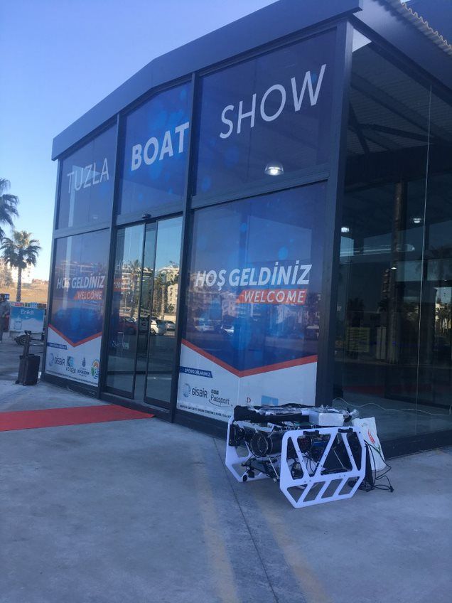
Istanbul Technical University Autonomous Underwater Vehicle

                                                                                       State      Description
scheduler, to offer improved efficiency and a modular                                   px        Position x
system.                                                                                 py        Position y
     d) Acoustic Signal Processing Board: To detect the                                 pz        Position z
                                                                                                Quaternion w
azimuth of a sound wave, an acoustic signal processing                                  qw
                                                                                        qx       Quaternion x
board was designed. Due to the shape and limited space                                  qy       Quaternion y
of the hydrophone housing, PCB split into 2 sections as                                 qz       Quaternion z
                                                                                                  Velocity x
lower section and upper section. The main task of the                                   vx
                                                                                        vy        Velocity y
Acoustic Signal Processing Board is azimuth detection                                   vz        Velocity z
by use of phase difference of the signals emerging from                                 wx     Angular Rate x
                                                                                               Angular Rate y
3 identical hydrophones. For superior anchorage of the                                  wy
                                                                                        wz     Angular Rate z
signal emerging from the pinger, Sixth Order Chebyshev                                        TABLE I
Band-Pass filter is used on the lower PCB section to                               Model Predictive Controller States
permit signals to be passed in the range of 31.28kHz-
61.73kHz. The signals are then passed through a digital
programmable differential amplifier and a buffer amplifier,
sequentially. The filtered signals are routed to the ADC
inputs of a STM32H7 type microcontroller which can                  task, is to perform the task as soon as possible and to
sample the signal with 16-bit resolution and 3.6MHz                 continue the task by making accurate decisions in the
sample rate.                                                        face of possible problems.

                                                                         c) Simulation: To observe and quickly test the mis-
                                                                    sion algorithms, object detection, and hydrodynamic /
                                                                    hydrostatic effects on the Turquoise; a simulation using the
                                                                    uuv_simulator [2] package was developed. The simulation
                                                                    is Gazebo based and ROS compatible for easy to use
                                                                    modularity. Thanks to this simulation, the testing phase
                                                                    of the algorithms, and therefore process of production and
                                                                    development of the algorithms has been accelerated.

      Fig. 12. Acoustic Signal Processing Board 3D View

WAVES [1] (Weighted Average of Signal Subspaces) al-
gorithm is implemented in the microcontroller with C
programming language to calculate the azimuth angle of
an incoming ping.
C. Software
     a) Control Navigation: To control the vehicle in all 6
axes, at first multiple PID controllers were used. But after
switching to a Model Predictive Controller a cost based                    Fig. 13. Simulation of Robosub Test Environment
tuning was implied. This outperformed the previous best
tuned PID controllers and also gave the opportunity to
control the vehicle with a reference state trajectory, rather         In order for the simulation to be realistic, the vehicle
than static reference.                                              features and parameters were taken from Autodesk Fusion
  The model was designed and implemented on MPC with                360 (CAD Software), Ansys (CFD analysis software) and
13 states which are described in Table I.                           some real-world test results. Also, all sensors on the vehicle
     b) State Machine: The flow of the missions is oper-            (IMU, Magnetometer, Depth/Pressure Sensors and Ping
ated by state machines. A state machine is a behavior               Sonars), cameras and thrusters have been modeled in the
model that comprises a finite number of states. According           simulation by their parameters. In addition, a kinematic
to the present state and a given data, the machine enforms          and dynamic model equations in ”Underwater Vehicle
state transitions and produces outputs. The goal of finite          Dynamic Modeling” [3] were taken as reference in the
state machines, which are designed one by one for each              mathematical modeling of Turquoise.

                                                                5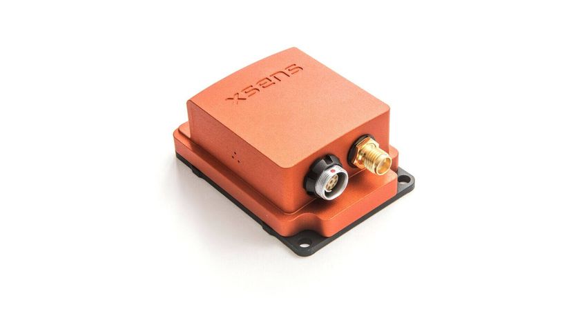
Istanbul Technical University Autonomous Underwater Vehicle

    Fig. 14. Example of Some Mission Objects in Simulation

                                                                              Fig. 16. Clarified Gate After Image Processing
   Additonally, a software called ”Fake Battery System”
was developed to predict energy consumption in the BMS
simulation environment, which is mentioned in the field of                            III. Experimental Results
electronics. By separating the static and dynamic forces              •   In order to keep the vehicle stable at a certain depth,
on the vehicle, the estimation algorithm was developed                    the algorithm written by our team was rearranged and
based on the power per 1 millisecond. A virtual battery                   the vehicle was stabilized. Thanks to this algorithm,
management system, which detects the energy consumed                      the collision of the vehicle with any place during close
and the remaining energy from the battery, was obtained.                  passes, possible reverse movements during torpedo
                                                                          shots were prevented, and it was determined in
                                                                          the experiments that it accomplished its tasks by
                                                                          consuming less energy than before.

Fig. 15. 3D Visualization of Turquoise on RViz With Topic Names

                                                                                        Fig. 17. Real World Test
     d) Computer Vision: Computer vision covers an
important part of the competition. Our main priority has              •   In pandemic conditions, where it was difficult for
been to achieve the most accurate and desired results                     the whole team to come together and go to the real
in a minimum time. First of all, a classical approach                     world test, the simulation made a great contribution.
using OpenCV [4] has been developed to detecting objects                  Specially, the ability of testing the image processing
with color correction, masking, getting borders and center.               algorithms and competition strategy in simulation has
Secondly, the data set is prepared and the collected data                 accelerated the team.
is replicated by data augmentation. Then, these collected             •   Our data set, which is masked and edited with
data sets were examined in different algorithms with                      image processing, is expanded with data augmen-
speed and accuracy criteria. It has been determined that                  tation. YOLOv4 and Faster R-CNN algorithms are
YOLOv4 [5] has priority in real-time detection and speed.                 trained with the expanded dataset. As a result of the
It has been observed that the accuracy rate is high as                    tests, the accuracy rate of YOLOv4 is between 95-
well as the detection speed. Our other option is Faster R-                99 percent and the accuracy rate of faster R-CNN
CNN [6]. This algorithm is both supported by TensorFlow                   is between 97.0-99.5 percent .In addition to detecting
Object Detection API [7] and is the fastest in training.                  objects, centres of objects are also detected. Although
Moreover, it was thought to work on different filters to                  physical tests could not be done adequately due to the
eliminate some mistakes while detecting. For instance,                    pandemic, many tests are carried out on simulation
Kalman Filter [8].                                                        and computer.

                                                                  6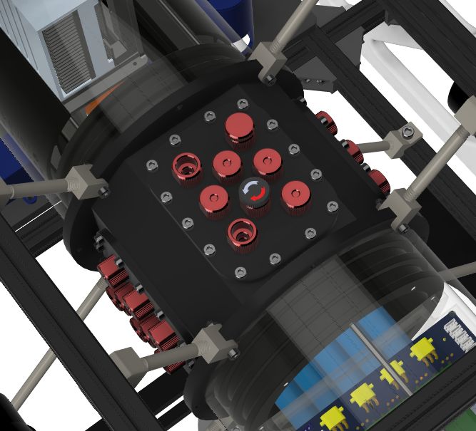
Istanbul Technical University Autonomous Underwater Vehicle

  •   Stability tests frequently done on Turquoise as new                rection finding,” IEEE Trans. Signal Process., vol. 49,
      materials added and olds removed. These tests were                 pp. 2179–2191, 2001.
      done in the circulation tanks and olympic pools in           [2]   M. M. M. Manhães, S. A. Scherer, M. Voss, L. R.
      our campus. During these tests it is observed that                 Douat, and T. Rauschenbach, “UUV simulator:
      vehicles stability continously changing with every                 A gazebo-based package for underwater interven-
      thing done on equipments. Trim of the vehicle have                 tion and multi-robot simulation,” in OCEANS 2016
      fixed everytime with added weights or buoyant foams.               MTS/IEEE Monterey, IEEE, Sep. 2016. doi: 10.1109/
  •   Turquoise used to have 6 thrusters and couldn’t done               oceans.2016.7761080. [Online]. Available: https://doi.
      all of the 6 DOF motions. To make Turquoise more                   org/10.1109%2Foceans.2016.7761080.
      mobile, 2 more thrusters have been added to the              [3]   S. Gomes, C. Moraes, P. Drews-Jr, T. Moreira, and
      design. These extra 2 thruster were located in the                 A. Tavares, “Underwater vehicle dynamic modeling,”
      Y direction and let the Turquoise make sway motion.                Jan. 2005.
  •   During the Acoustic Signal Processing Board ex-              [4]   G. Bradski, “The OpenCV Library,” Dr. Dobb’s
      periments, the copper paths of PCB were not kept                   Journal of Software Tools, 2000.
      equal for each hydrophone data, thus unwanted phase          [5]   A. Bochkovskiy, C.-Y. Wang, and H.-Y. M. Liao,
      angles emerged.The copper paths are adjusted equally               Yolov4: Optimal speed and accuracy of object de-
      in order to prevent this situation and unwanted phase              tection, 2020. arXiv: 2004.10934 [cs.CV].
      angles are prevented.                                        [6]   L. Zhang, L. Lin, X. Liang, and K. He, “Is faster r-cnn
  •   Since the voltage follower was not placed in the                   doing well for pedestrian detection?” In Computer
      voltage divider circuit, 1.65V DC voltage received was             Vision – ECCV 2016, B. Leibe, J. Matas, N. Sebe,
      not stable. After the situation was noticed, a voltage             and M. Welling, Eds., Cham: Springer International
      follower was placed in the circuit and stability was               Publishing, 2016, pp. 443–457, isbn: 978-3-319-46475-
      ensured.                                                           6.
  •   Hydrophones were directly connected to 5V DC                 [7]   P. Mustamo, Object detection in sports: Tensorflow
      voltage and were grounded in common. For this                      object detection api case study, P. Mustamo, Ed.,
      reason, unwanted noise has occurred and damaged the                2018. [Online]. Available: http://jultika.oulu.fi/files/
      received data. Later, a separate DC/DC Converter                   nbnfioulu-201802081173.pdf.
      was used for each hydrophone and the grounding was           [8]   S.-K. Weng, C.-M. Kuo, and S.-K. Tu, “Video object
      made separately for each hydrophone to correct this                tracking using adaptive kalman filter,” Journal of
      situation. In this way,noise is prevented.                         Visual Communication and Image Representation,
  •   During the placement of the cables in the vehicle,the              vol. 17, no. 6, pp. 1190–1208, 2006, issn: 1047-3203.
      distance between the cables which draw high current                doi: https : / / doi . org / 10 . 1016 / j . jvcir . 2006 . 03 . 004.
      and the cables which transmit the sensor data were                 [Online]. Available: https://www.sciencedirect.com/
      became very close and the data which emerge in                     science/article/pii/S1047320306000113.
      sensors damaged. The cables that draw high current
      were coated with aluminum in order to prevent this
      situation.
                      Acknowledgment
   ITU AUV Team would like to thank, the team’s
faculty advisor Bilge Tutak, due to their encouraging,
devoting support during this period. The team would
like to thank the ITU Faculty of Naval Architecture and
Marine Sciences for the study space and opportunities
they have provided. The team would also like to thank
Vatan Aksoy Tezer for his guidance and assistance from
the very beginning, and also thank to Sencer Yazıcı for
his willing leadership. The team is grateful for all of
aid and polite donations that improve AUV’s features
from Altium, Autodesk, ITU, Tekhnelogos. The biggest
appreciation goes to every member who has worked hard
to improve the AUV so far.
                         References
[1] E. D. D. Claudio and R. Parisi, “Waves: Weighted
    average of signal subspaces for robust wideband di-

                                                               7
Istanbul Technical University Autonomous Underwater Vehicle

                                                            TABLE II
                                                       Component Specifications

 Component                      Vendor                  Model/Type                        Specs   Cost(if new)   Status
 Buoyancy Control               -                       -                                 -       -              -
 Frame                          -                       Aluminium Sigma Profiles          -       25$            installed
 Waterproof Housing             BlueRobotics            Cast Acrylic Tube 6”              link    98$            installed
 Waterproof Connectors          BlueRobotics            Penetrator                        -       0              installed
 Thrusters                      BlueRobotics            T100                              link    169$           installed
 Motor Control                  BlueRobotics            Basic ESC                         link    27$            installed
 High Level Control             ITU AUV Team            Model Predictive Controller       -       -              -
 Actuators                      ITU AUV Team            Torpedo & Bin Dropper             -       -              installed
 Propellers                     Built-in w/Thrusters    -                                 -       -              installed
 Battery                        Sony                    US18650VTC6 Custom Pack           link    250$           installed
 Converter                      Analog Devices          LTC3780                           link    16$            installed
 Regulator                      -                       -                                 -       -              -
 CPU                            Nvidia                  Jetson Xavier                     link    750$           installed
 Internal Comm Network          TP-Link                 TL-SF1005D                        link    7$             installed
 External Comm Interface        BlueRobotics            Fathom X                          link    159$           installed
 Compass                        Built-in w/IMU          -                                 -       -              installed
 Inertial Measurement Unit      XSens                   MTi-G-710                         link    4500$          installed
 (IMU)
 Doppler     Velocity    Log    Navquest                600 Micro                         link    10500$         installed
 (DVL)
 Vision                         Sony                    IMX219 (Raspberry Pi Camera v2)   link    50$            installed
 Stereo Vision                  StereoLabs              ZED                               link    350$           installed
 Acoustics                      Aquarian Audio          H2C Hydrophones                   link    120$           installed
 Sonars                         BlueRobotics            Ping Sonar                        link    279$           installed
 Pressure Sensor                BlueRobotics            Bar30                             link    72$            installed
 Light(s)                       BlueRobotics            Lumen SubSea Light v2             link    119$           installed
 Mainpulator                    -                       -                                 -       -              installed
 Algorithms: vision             YOLOv3                  -                                 -       -              installed
 Algorithms: acoustics          WAVES                   -                                 -       -              installed
 Algorithms:     localization   robot_localization &    -                                 -       -              installed
 and mapping                    ORB-SLAM
 Algorithms: autonomy           ITU AUV Team            -                                 -       -              installed
 Open source software           OpenCV & ROS &          -                                 -       -              installed
                                FreeRTOS
 Team Size (number of peo-      39                      -                                 -       -              installed
 ple)
 Expertise ratio (hardware      H: 20, S: 19            -                                 -       -              installed
 vs. software)
 Testing time: simulation       300-350h                -                                 -       -              installed
 Testing time: in-water         150h                    -                                 -       -              installed
 Inter-vehicle communica-       -                       -                                 -       -              installed
 tion
 Programming Language(s)        C & C++ & Python        -                                 -       -              installed

                                                                    8
Istanbul Technical University Autonomous Underwater Vehicle
Appendix B: Outreach Activities
As the ITU AUV Team, we are aware of the importance
of transferring knowledge to future generations, and we
have participated in many activities to interact with
STEM students and Robotics interests. In the last two
years, 2020 Boat Show, Inovatim and as ITU Project
teams, we had the opportunity to meet with Robotics-
related students from Beşiktaş Anatolian High School.
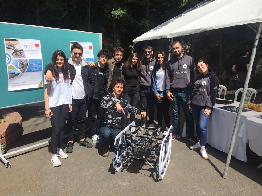
Fig. 19. Our Team in Inovatim
In the 2020 Boat Show, we came together with lots
of underwater admirers and had a chance to meet them.
From the first minute, we were greeted enthusiastically. destroyed the stereotypes in the minds of many students
Our stand has aroused great interest in people as came to who want to become engineers and have shown new areas
our stand and examined the vehicle and asked questions. in engineering for them.
For both us and the participants, it was one of the most
productive activities. We had the opportunity to meet a
lot of new people and exchange information, thanks to
this event. In conclusion, with more networks we were
provided, it was easier to access the sponsors we needed
for our vehicle.
Fig. 20. Our Stand in Beşiktaş Anatolian High School
Fig. 18. Photograph From Boat Show
We also took a part in Inovatim’s activity, Innovation
Week in 2019. Inovatim, which is a subsidiary of the
Turkish Exporters Assembly, tries to instill innovation in
young people and to develop innovation studies in Turkey.
Thanks to Inovatim, we had a chance to open our stand
at this event. We had the opportunity to chat on many
topics, from what materials other teams use to how the
team works. Thus, we had the chance to look not only
from our own point of view but also from other aspects.
We topped this event off with the award we received by
participating in a competition within the event.
Other than our generation, for inspiring the future
STEM students the best way to introduce the underwater
world is by meeting with the high schools. In this matter,
we went to the Beşiktaş Anatolian High School and met
with lots of students. We think that we have attracted
many students about the submarine engines, from the
slightly interested to the very interested, furthermore, we
invited them to our school. We have shown that we have
9
You can also read