Digital Twin for Anti-lock Braking System in Virtual Reality
←
→
Page content transcription
If your browser does not render page correctly, please read the page content below
TALLINN UNIVERSITY OF TECHNOLOGY
 School of Information Technologies

 Maksym Kosiuk 194206IASM

Digital Twin for Anti-lock Braking System in
 Virtual Reality

 Master's thesis

 Supervisors: Aleksei Tepljakov
 Ph.D.
 Saleh Ragheb Saleh Alsaleh
 M.Sc.

 Tallinn 2021

TALLINNA TEHNIKAÜLIKOOL
 Infotehnoloogia teaduskond

 Maksym Kosiuk 194206IASM

ABS-pidurisüsteemi digitaalse kaksiku
 kasutamine virtuaalreaalsuses

 Magistritöö

 Juhendaja: Aleksei Tepljakov
 Ph.D.
 Saleh Ragheb Saleh Alsaleh
 M.Sc.

 Tallinn 2021
Author’s declaration of originality

I confirm that I am the sole author of this thesis. The materials of other works that are
used here are referenced. The work has not been submitted elsewhere and has not been
presented for examination.

Author: Maksym Kosiuk

05.05.2021

 3
Abstract

Anti-Lock Braking system is a system that monitors and controls wheels while slipping
or during braking of vehicle. It helps to improve stopping distance and provide an
additional control on vehicles. Digital twin is a digital copy of a desired object that
behaves as a real object and it is modelled on a computer (in case of this study, in Unreal
Engine software). Virtual Reality is an environment that simulates another experience on
personal computers. It is supposed to be a different representation of the world and it
could be used for different purposes (for example, simulations that are similar to real
world conditions). This work discusses the potential use of Anti-Lock Braking system as
a digital twin using virtual reality. This field of study is not well investigated and needs
more attention. The possibility to interact with the virtual world and affect the real
environment creates new interesting challenges that look inspiring. Anti-Lock Braking
system is not an exception. This thesis will show what is done so far in the mentioned
field and what steps could be made in order to create such virtual environment using
digital twin of Anti-Lock Braking system, Virtual Reality, and physical Anti-Lock
Braking system itself. In the end, reader will understand the main concept of digital twin
of Anti-Lock Braking system in Virtual Reality application in Unreal Engine 4
environment. Overall, there are achievements. Matlab model was created and it interacts
with Unreal Engine using UDP protocol. A digital copy of Anti-Lock Braking system
was created in Unreal Engine 4 and it moves almost synchronously with real Anti-Lock
Braking system. At last, characteristics of digital twin of ABS were applied to wheels on
a virtual car.

 The VR-based application is developed by a team of 2 students. However, the
progress is divided into 2 parts. One of them is dealing with hardware-in-the-loop, another
– simulation only in UE4. This thesis describes the second side of the project: simulation
only in UE4. The project was forked, so it is not the same, but it has similarities with
another one that is used by another student. The contributions in this case are a little bit
different.

 Thesis is completed in English and it contains 53 pages, 5 chapters, 3 tables, and
30 figures.

 4
List of abbreviations and terms

VR Virtual Reality
ABS Anti-lock Braking System
UDP User Datagram Protocol
UE4 Unreal Engine 4
ECU Electronic Control Unit
PID Proportional-Integral-Derivative
3D 3-Dimentsional
LED Light-Emitting Diode
IR Infra-red
RAM Random Access Memory
CPU Central Processor Unit
GPU Graphics Processing Unit
USB Universal Serial Bus
PC Personal Computer
RPM Rotations Per Minute
FPS Frame Per Second
HDMI High Definition Multimedia Interface

 5
Contents

1 Introduction ................................................................................................................. 10
 1.1 Literature review................................................................................................... 12
 1.2 ABS overview....................................................................................................... 14
 1.2.1 Description .................................................................................................... 14
 1.2.2 Physical model............................................................................................... 16
 1.2.3 Mathematical model ...................................................................................... 17
 1.3 Software used in the development ........................................................................ 22
 1.3.1 Matlab as a supportive environment.............................................................. 22
 1.3.2 Unreal Engine 4 as a virtual environment ..................................................... 22
 1.4 Definition of VR ................................................................................................... 23
 1.5 Hardware and equipment used in the development .............................................. 23
 1.5.1 Oculus Rift VR headset ................................................................................. 24
 1.5.2 Steering wheel Logitech G29 ........................................................................ 25
 1.6 Problem ................................................................................................................. 26
 1.7 Purpose ................................................................................................................. 26
 1.8 Goal ...................................................................................................................... 27
 1.9 Motivation ............................................................................................................ 27
2 System design and development.................................................................................. 28
 2.1 Development approaches ...................................................................................... 28
 2.2 System design ....................................................................................................... 29
 2.3 Car model in Unreal Engine 4 .............................................................................. 31
 2.3.1 Acceleration of the vehicle ............................................................................ 32
 2.3.2 Brake control of the vehicle .......................................................................... 33
 2.3.3 Reversing gear ............................................................................................... 35
 2.4 Model of ABS in Unreal Engine 4 ....................................................................... 35
 2.4.1 Wheel distance measurement ........................................................................ 35
 2.4.2 Wheel speed measurement ............................................................................ 36
 2.4.3 Travel distance measurement ........................................................................ 37
 2.4.4 Vehicle speed measurement .......................................................................... 38
 2.4.5 Slip coefficient calculation ............................................................................ 39
 2.4.6 Controller block ............................................................................................. 40

 6
2.5 Graphs in UE4 ...................................................................................................... 40
 2.5.1 Acceleration input graph ............................................................................... 41
 2.5.2 Brakes state graph.......................................................................................... 42
 2.5.3 Wheel velocity graph ..................................................................................... 43
 2.5.4 Car’s engine velocity graph ........................................................................... 44
 2.5.5 Travel distance graph .................................................................................... 45
 2.5.6 Slip coefficient graph .................................................................................... 46
 2.5.7 Wheel speed graph ........................................................................................ 47
 2.5.8 Car speed graph ............................................................................................. 48
 2.6 Analysis of the results........................................................................................... 49
3 Summary...................................................................................................................... 50
4 Discussion and Future Work ....................................................................................... 51
5 References ................................................................................................................... 52

 7
List of figures

Figure 1. ABS system components ................................................................................ 14
Figure 2. Inteco ABS ...................................................................................................... 16
Figure 3. Schematic diagram of ABS ............................................................................. 17
Figure 4. Auxiliary diagram of moments of forces in ABS model ................................ 19
Figure 5. Oculus Rift set ................................................................................................. 25
Figure 6. Steering wheel and playseat Logitech G29 ..................................................... 26
Figure 7. Main menu of the application ......................................................................... 29
Figure 8. System diagram of connections ...................................................................... 30
Figure 9. Steering wheel logic section in Blueprint ....................................................... 30
Figure 10. Decision diagram for Steering Wheel logic .................................................. 31
Figure 11. The model of a car......................................................................................... 32
Figure 12. Whole visual logic of “Gas input” section in Blueprints .............................. 33
Figure 13. Decision diagram for Acceleration of the vehicle wheels ............................ 33
Figure 14. Whole visual logic of “Brake input” section................................................. 34
Figure 15. Decision diagram for Brake control of the vehicle ....................................... 34
Figure 16. Logic for reserving gear of the car ................................................................ 35
Figure 17. Whole visual logic of calculating passed distance by the fourth wheel ........ 36
Figure 18. Whole visual logic of calculating speed of the fourth wheel ........................ 37
Figure 19. Whole visual logic of calculating distance of the vehicle ............................. 38
Figure 20. Whole visual logic of calculating speed of the vehicle ................................. 39
Figure 21. Whole visual logic of calculating slip coefficient ......................................... 39
Figure 22. Graph selection menu .................................................................................... 41
Figure 23. Acceleration input graph sample from the application ................................. 42
Figure 24. Brakes state graph sample from the application ........................................... 43
Figure 25. Wheel’s velocity graph sample from the application .................................... 44
Figure 26. Car’s engine velocity graph sample from the application ............................. 45
Figure 27. Car distance graph sample from the application ........................................... 46
Figure 28. Slip coefficient graph sample from the application ...................................... 47
Figure 29. Wheel speed graph sample from the application .......................................... 48
Figure 30. Car speed graph sample from the application ............................................... 49

 8
List of tables

Table 1. Parameters of the model ................................................................................... 17
Table 2. Model coefficients values ................................................................................. 21
Table 3. Computers’ characteristics ............................................................................... 24

 9
1 Introduction

 Anti-lock braking system (ABS) is designed for controlling and monitoring wheel
slip when a vehicle starts braking. It is an electronic vehicle safety system that helps to
improve stopping distance. As brakes are applied to the car, the wheel speed begins to
decrease. A decrease in vehicle speed does not necessarily lead to a decrease in wheel
velocity. The non-correspondence between the speed of a wheel and the speed of the
vehicle is called slip. Its magnitude is represented in formula (1).

 − ∙
 = ∙ 100 (1)

Where,
 – Vehicle Speed
 – Radius of wheel
 – Angular speed of wheel

 For the development, ABS from Inteco is used. It is not perfect in terms of
hardware and calibrations, but it is considered to be a good object for the beginning.
Worth to mention that it was used before by other researchers. Therefore, the obtained
results from the model could be not satisfactory in terms of efficiency.

 The topic of digital twin is not new, but interesting in many perspectives. It is
important concept in various industries. Generally, digital twin is a digital representation
of a physical object. It could simulate the same functionality as the real object. However,
there are needs to display real actions of the real object or, even, control it through digital
twin. Usually, sensors are used in order to have a communication between digital twin
and object. Additionally, digital twin could be a separate instance with its own
characteristics. However, the final goal in the current investigation to achieve is to make
it similar or, ideally, the same as a real object that could work independently. In summary,
digital twin can be described as a physical asset’s virtual representation that could be
accessed through simulators and data for real-time prediction, controlling, optimization,
improved decision making, and monitoring [2].

 10
ABS from Inteco is going to be used for creating a digital twin. At the end, it
should be the same or similar to the real object in terms of characteristics and
functionality.

 Usually, Virtual Reality (VR) is defined in terms of technological hardware that
generates the dimensions of experience in an interactive or para-reality environment that
provides various degrees of vividness and interactivity. VR headset wearers use either
tethered or wireless controls with built-in sensors to track hand movements in order to
generate input for simulation. For HTC Vive-like devices (e.g., Sony PlayStation VR,
Oculus Rift, and Oculus Touch), wearers keep two controllers and use VR simulation
keys, thumbsticks, and triggers to register actions. Wearers are also able to see their hands
through the headset on the show [3].

 In case of this thesis, the final goal is creating a virtual environment where a user
can test ABS and see how it works in basic and advanced terms. Unreal Engine, driving
steering wheel Logitech G29, and Oculus VR headset are used in order to create a virtual
environment. The final goal is to create a simulation in Unreal Engine with a car that have
simulated ABS on its wheels. This final simulation should be controlled using Logitech
G29 and/or Oculus Rift VR headset.

 11
1.1 Literature review

 In this section, the literature (mainly from IEEE Xplore and ResearchGate) is
reviewed from the point of usefulness. There are many conference papers found, however
they are not considered as solid sources. Some of them can be considered as ways for the
further development, but they are not robust. However, some of the conference papers are
listed here since they are closely related to the current topic.

 When it comes to the definitions of digital twin and virtual reality domains, they
are excellently described in [2] and [3] respectively. These sources are used for the
explanation in Section 1. Also virtual reality domain is explained in [14] in very detailed
manner. These sources could be a good starting point if there is a need to understand the
essence of the topic fully.

 In general, there were little researches in the study field related to digital twin of
ABS. There was a good attempt to push forward a topic related to efficiency of ABS and
a there was a proposal to use a simulation test and virtual reality technology in order to
improve it [4]. This is closely related to the topic of the investigated research. It is not
fairly new (2012), but its results could be useful for further developments. For instance,
there are some interesting and useful results that could be used in the development. The
connection between virtual environment and physical mode was described in a good
manner including mathematical formulas. However, LabVIEW was used here as a
communication channel between physical and virtual environment. This work is great to
use in further development since it follows almost the same goal: creating a safe
environment for learning ABS. But the “virtual reality” is presented here as 3D
application which makes the reading of the article a little bit confusing from the modern
point of view. Considering the usefulness of the article in the current stage, it is valuable
source for developing hardware-in-the-loop applications. However, the scope of the thesis
is the simulation part of ABS and the source was valuable at the beginning of the
development.

 It would be weird, but it is the only document that can be found regarding
developing ABS on virtual reality domain. Next sources describe mathematical models
of controllers which are, actually, pretty good when it comes to developing simulation of
ABS in UE4.

 12
One more research that came at the same year as previous article describes how
to make a fuzzy control on Matlab which is considered as a main instrument for
communication with ABS directly [5]. This document concludes that fuzzy control is
worth to be further developed. It could be considered as an additional brunch for further
developments in the research, but, since it is a conference paper, it is not considered as a
solid source. It proposes methods that could be efficient and reduce braking distance
additionally comparing to basic controllers.

 When it comes to control strategy of ABS, there is an article that is worth for
mentioning. It proposes to use control method for single wheel that is based on Lyapunov
stability theory [6]. The method is supposed to be used for maximizing tire-road friction
and minimizing yaw moment of a commercial vehicle. Comparing to the previous source,
it proposes an efficient controller, and it has detailed mathematical model for it. The
mathematical model in this is computed using Matlab environment. This mechatronics’
article from journal could be a robust source for upgrading the current project in UE4
simulation. It is worth to emphasize that it is appliable on one wheel, but later the model
could be applied on other wheels too. Since this article describes control strategy for
commercial vehicles, it is absolutely gold.

 However, the scope of this project is to apply ABS on all the wheels. There is a
very good source related to it. It discusses the use of ABS on each wheel separately and
how effective PID controller can be applied [18]. The theory is based on wheel slip
control and it is explained using Matlab environment. It would be a great source for
applying controllers in UE4 in the future. This is relatively fresh source from 2020 and
its results are satisfactory. This source can be used in order to proceed with the current
topic.

 Unfortunately, there were no researches about digital twin of ABS and connection
of ABS with virtual reality headsets. In addition, the attempts to implement ABS on UE4
were not found. All the developments in the thesis are based on the findings from each
document in the references list and on the developments from other students.

 13
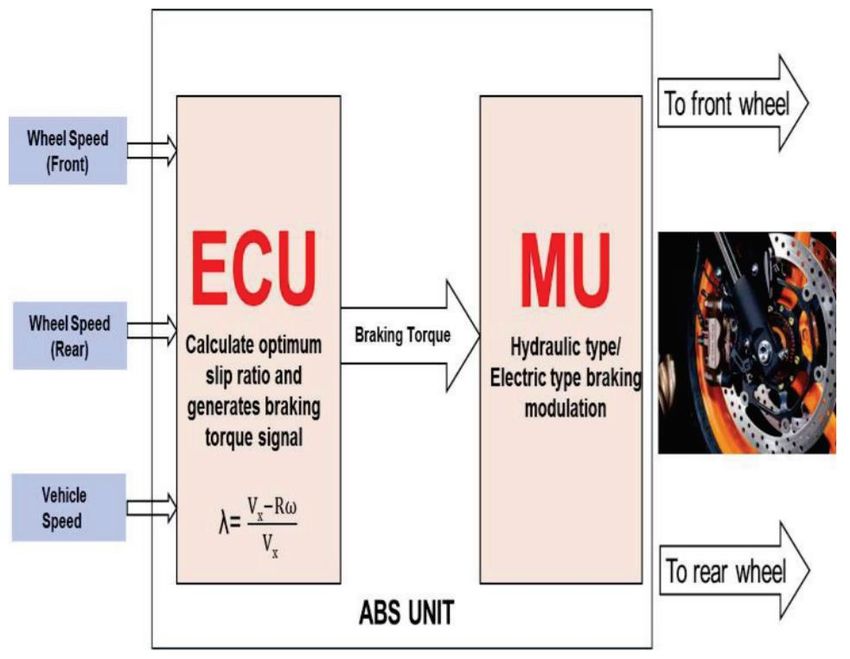
1.2 ABS overview

 This section provides an overview of ABS and its existing models that are kindly
provided by Inteco. It describes the system itself and its limitations. Mathematical models
are not fully described in the thesis and full reference can be found here [13].

1.2.1 Description

Usually, the ABS system is composed of subsystems:

 • Wheel Speed Sensor
 • Electronic Control Unit (ECU)
 • Hydraulic Pressure Modulator
Other inputs such as roll angle sensor, gyroscope sensors, acceleration sensors are used
in the advanced ABS system to realize advanced features such as HSA (Hill start assist),
Curve traction control, cornering ABS, lateral stability control, etc [1].

 Figure 1. ABS system components
 Wheel Speed Sensor: In the case of two ABS channels two wheel sensors are used,
i.e. the front wheel and the rear wheel. This wheel sensor continuously tracks the speed
of the wheel and senses the rapid deceleration of the vehicle. These sensors are mounted
near a spinning disk or, in some situations, toothed rings are used for electromagnetic or
Hall-effect pulse pickups and are mounted directly on the rotating components of the
wheel hubs. In certain ABS cases, the speed of the vehicle is determined from the speed
 14
of the wheel using an estimation algorithm such as Kaman's filtering, observer design, etc [1]. Electronic control unit (ECU): It is clear from Figure 1 that the performance of the wheel speed sensors is supplied as an input to the ECU, which then calculates the slip ratio and produces an optimum braking torque to prevent the wheel from being locked. Operations such as slip comparison and velocity estimation are carried out in ECU. The output signal produced is given to the hydraulic pressure modulator [1]. Hydraulic Pressure modulator: Hydraulic Pressure Modulator is an electrohydraulic pressure modulation system, i.e. minimizing, retaining and building pressure. It consists of electromagnetic solenoid valves, pump motor, pressure sensors and accumulators. The ECU output signal actuates the solenoid valves and the engine to achieve intended resistance while the pressure sensor measures the pressure within the calipers [1]. The above is a general description of ABS. Inteco ABS is used and the main characteristics and features listed below [13]. Key features: • Double-wheel laboratory model of ABS equipped with powerful flat DC motor; • Two high-resolution measuring encoders; • Full integration with MATLAB / Simulink. Operation in real-time in Windows XP/W7 32bit; • Complete model of the car-road relations; • Library of pre-programmed braking control algorithms familiarize the user with ABS technique in a fast way; • Rapid prototyping of real-time control algorithms. No C-code programming; • Ideal illustration of nonlinear control algorithms. Key benefits: • Enables to provide laboratory tests of the antilock braking system in the car velocity range from 0 to 50 km/h; • Accelerates implementation of new slip control algorithms; • Demonstrates the slip control under different road conditions. 15
Figure 2. Inteco ABS

1.2.2 Physical model

 Physical model of ABS consists of two wheels. Upper one, which is made of
plastic, represents car wheel whereas lower wheel, which is made of iron, represents road
wheel. Additionally, the model contains of PWM derived motor which accelerates road
wheel and, by contact, car wheel. Braking is done by switching off the motor and
activating braking disk that is on car wheel. Road wheel is much heavier to represent
moment of inertia of road wheel.

 16
Figure 3. Schematic diagram of ABS [13]

1.2.3 Mathematical model

 This section discusses the mathematical model of laboratory ABS. This
mathematical model is given since it is a part of the project. For instance, slip coefficient
calculations are used in the UE4 project. However, it is given for an understanding that
Inteco laboratory model has its own limitations that is not appliable in UE4, but they
explain why the mathematical model of this model is different from the model that is
given in UE4. Additionally, it is a part of hardware-in-the-loop project part that is done
by another student.

 Before giving explanation about the model, it is worth to define the parameters
first [13]. In addition, further explanations and discussion in this chapter are based on the
following sources: [11], [13].

 Table 1. Parameters of the model
 Name Description Units
 1 Angular velocity of the upper wheel rad/s
 2 Angular velocity of the lower wheel rad/s
 1 Braking torque Nm
 1 Radius of the upper wheel m
 2 Radius of the lower wheel m
 1 Moment of inertia of the upper wheel kgm2

 17
 2 Moment of inertia of the lower wheel kgm2
 1 Viscous friction coefficient of the upper wheel kgm2/s
 2 Viscous friction coefficient of the lower wheel kgm2/s
 Total force generated by the upper wheel and pressing on the lower N
 wheel
 ( ) Friction coefficient between the wheels
 Slip – the relative difference of the wheels velocities
 10 Static friction of the upper wheel Nm
 20 Static friction of the lower wheel Nm
 Gravitational and shock absorber torques acting on the balance lever Nm
 Distance between the contact point of the wheels and the rotational m
 axis of the balance lever
 Angle between the normal in the contact point and the line L °
 Control of the brake

 Two wheels are described using Newton’s second law for rotational motion (2).

 ∑ = ̈ (2)

 Using auxiliary diagram of ABS in Figure 3, the motion equation for the upper
wheel can be described using equation (3).

 1 ̇ 1 = 1 − 1 1 − 1 10 − 1 1 (3)

 The motion equation for the lower wheel can be described using equation (4).

 2 ̇ 2 = − 2 − 2 2 − 2 20 (4)

 18
Figure 4. Auxiliary diagram of moments of forces in ABS model [13]

 Auxiliary variables, introduced in formulas (5), (6), and (7), are used to
distinguish the direction of rotation of wheels.

 = ( 2 2 − 1 1 ) (5)

 1 = ( 1 ) (6)

 2 = ( 2 ) (7)

 Slip coefficient is defined in formula (8) as relative difference of the wheels
velocities.

 19
 2 2 − 1 1
 ; 2 2 ≥ 1 1 , 1 > 0, 2 >0
 2 2
 1 1 − 2 2
 ; 2 2 < 1 1 , 1 > 0, 2 >0
 1 1
 2 2 − 1 1
 = ; 2 2 < 1 1 , 1 < 0, 2 0, 2 < 0

 Next equations in formulas (9), (10), and (11) are describing nonlinear state
model. It is done to simplify the model since if the parameters above are substituted then
the model becomes too complicated.

 ̇ 1 = ( )( 11 1 + 12 ) + 13 1 + 14 + ( 15 ( ) + 16 ) 1 1 (9)

 ̇ 2 = ( )( 21 1 + 22 ) + 23 2 + 24 + 25 ( ) 1 1 (10)

 ̇1 = 31 ( ( ) − 1 ) (11)

 Model coefficients that are mentioned here such as 11 are listed in Error!
Reference source not found.. They are used to simplify the model. They are calculated
using formulas (12), (13), (14), (15), (16), (17), (18), (19), (20), (21), and (22).

 1 1
 11 = (12)
 1

 ( 1 10 + ) 1
 12 = (13)
 1

 1
 13 = − (14)
 1

 1 10
 14 = − (15)
 1

 1
 15 = (16)
 1

 20
1
 16 = − (17)
 1

 2 1
 21 = − (18)
 2

 ( 1 10 + ) 2
 22 = − (19)
 1

 2
 23 = − (20)
 2

 2 20
 24 = − (21)
 2

 2
 25 = − (22)
 2

 S and functions are defined in formulas (23) and (24) which were obtained from
formulas (9), (10), and (11).

 ( )
 ( ) = (23)
 ( − ( ) )
 4
 ( ) =
 + 3 3 + 2 2 + 1 (24)
 +
 Following coefficient values in Error! Reference source not found. are used in
default in mathematical model following recommendations from Inteco.

 Table 2. Model coefficients values
 11 = 0.00158605757097 12 = 2.593351896228796e + 002

 21 = 13 = 0.01594027709515 14 = 0.39850692737875

 15 = 13.21714642472868 16 = 132.8356424595848

 21 = 0.000464008124048 22 = 75.86965129086435

 23 = 0.00878803265242 24 = 3.63238682966840

 25 = 3.86673436706636 31 = 20.37

 21
 1 = 0.04240011450454 2 = 0.00000000029375

 3 = 0.03508217905067 4 = 0.40662691102315

 = 0.00025724985785 = 2.09945271667129

 Please, take note that this mathematical model describes the behaviour of 2 wheels
where, in fact, it helps to observe the behaviour of ABS on one-wheel vehicle only. So, it
was suitable to use at the beginning for observation how ABS works.

1.3 Software used in the development

 This section provides an overview of software that is used in the development of
thesis. There are 2 main instruments listed here. Visual Studio is not listed since visual
programming (Blueprint) in UE4 was used instead of coding.

1.3.1 Matlab as a supportive environment

Matlab is a programming and mathematical tool which was developed to support
scientific researches. It was developed in 1984 and it is still supported until these days
[14]. The main languages here are C and C++. There is also possibility here to use
Simulink as a visual programming which makes life easier for researchers. On the project
its usage is valuable when it comes to real-time communication with the ABS Inteco
laboratory stand. The Simulink model is kindly provided by Inteco and it is a good
supportive tool for understanding all the interfaces that are connected. Of course, the
provided models are not ideal, but the drivers made life easier for the project participants.
Worth to mention that UDP communication channel could be used here which is a great
possibility to communicate with UE4 in order to create hardware-in-the-loop model. This
part is done by another participant, but the author of the document participated into
development of the controller and logic.

1.3.2 Unreal Engine 4 as a virtual environment

 Unreal Engine is a software tool that is used for real-time 3D creativity. It is
developed by Epic Games company and first time it was used for developing games since
it is a game engine [8]. However, after passing some time, the tool has started to be
interesting for scientific researches [9]. Since it is flexible and easy to use even for
 22
complete beginners, it is a good software for developing projects based on VR. The main
programming language here is C++, but there is a possibility to use “Blueprints” (visual
scripting system). Oculus Rift VR headset is used along with Unreal Engine and it is a
good and stable combination for debugging and developing [10]. For communication
between UE4 and Matlab, UDP (User Datagram Protocol) is used. It makes possible to
do real-time operations between digital twin and the real object. It is worth to mention
that it is possible to simulate physics and mathematical calculations in UE4 for every
object and achieve immediate results. This tool is the primary one in the development and
all the final achievements obtained here. The progress and results will be elaborated more
in Section 2.

1.4 Definition of VR

 Virtual Reality is a simulated experience of reality in hardware devices that differs
from the real world. However, it is more accurate to say that VR is an experience of
presence in the Virtual Environment as it is described in [15]. So, in the thesis VR and
Virtual Environment are simulated through software and hardware packages which make
a feeling that the world is different and there is a possibility to interact with it. From the
source, „Interactivity is defined as the extent to which users can participate in modifying
the form and content of a mediated environment in real time.” Consequently, „Interaction
is defined as the action with which users can participate in modifying the form and content
of a mediated environment in real time.”.

1.5 Hardware and equipment used in the development

 This section describes used equipment in the project. The equipment was kindly
provided by TalTech representatives for the development. In addition, there are 2 personal
computers used with following characteristics:

 23
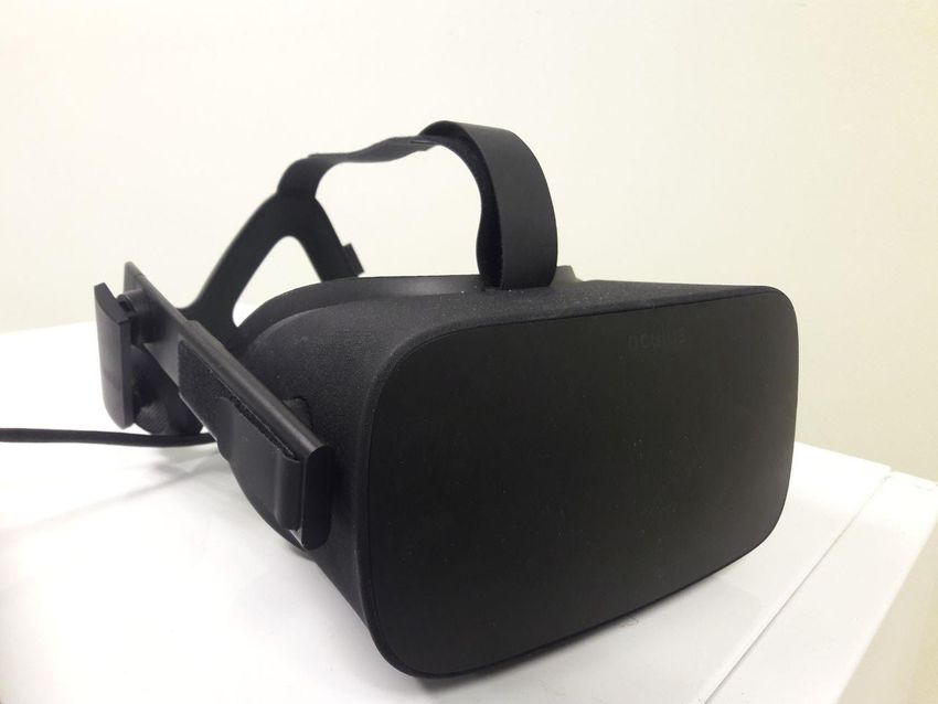
Table 3. Computers’ characteristics

 Computer number 1 2

 CPU Intel(R) Core(TM) i7- Intel(R) Core(TM) i7-
 6700K CPU @ 4.00GHz 7700 CPU @ 3.60GHz
 4.00 GHz 3.60GHz

 GPU NVIDIA GeForce GTX Intel (R) HD Graphics
 980 Ti 630

 Purpose of using -Developing applications -Developing applications
 on UE4 in Matlab;
 -Real-time
 communication with
 ABS.

 RAM, GB 32 16

 HDD memory, GB 2000 -

 SDD memory, GB 500 250

1.5.1 Oculus Rift VR headset

 Oculus Rift is a device that is used for interacting with Virtual Environment. It is
a soft and comfortable headset with custom optics inside and headphones. Optics are used
to create immersive 3D environment. Touch controllers are used as trackers for hands.
These controllers are tracked by IR LEDs (that looks like cameras) that should be
calibrated by the user. Since it is an old version of headset that is used in this project, the
IR LEDs are separate instances from VR headset and should be placed in front of the
place that is going to be used [16].

 24
Figure 5. Oculus Rift set

1.5.2 Steering wheel Logitech G29

 Playseat and Steering wheel Logitech G29 is a device that is used to simulate the
experience of driving at home conditions without risks if there is a wish to drive hard. For
the project development, this tool is considered to be absolutely necessary since it helps
the user to feel the connection with the simulated environment. The device is fairly
simple. It has a set of buttons, pedals, and steering wheel that could rotate by 900 degrees.
Additionally, there is a force feedback on the steering wheel. Dual-motor force feedback
creates a feeling that there is a tire slip [17].

 25
Figure 6. Steering wheel and playseat Logitech G29

1.6 Problem

 As it is stated at the beginning, ABS is used widely in different vehicles such as
cars, planes, or motorcycles. It is an important part since it provides an additional control
to the vehicles and improves the performance overall. Of course, there are simulations
that are already developed and could be useful for trainings and investigations. However,
it does not provide a full experience of driving still. There is a need to develop an
application that could be better than predecessors. There is no VR application still for
experiencing ABS behaviour in cars or motorcycles.

1.7 Purpose

 The purpose of the thesis is to suggest a different approach to the problem.
Fortunately, there are many possibilities these days for the improvement. For instance, in
this project Steering Wheel, pedals, and VR headset are used as equipment for
experiencing dangerous scenarios. There is an obvious difference here comparing to

 26
traditional approaches using on-screen 3D applications only. Since VR technologies grow
fast these days, it is worth to try to develop such application and try a different approach
which could lead to further developments in this field. In addition, it would be interesting
for researches who are interested in mechanics side. So, there is additional purpose to
develop such an application where it is easy to observe ABS behaviour and develop
feasible controller.

1.8 Goal

 The main objective of the thesis is to create a virtual environment where it is easy
to observe ABS behaviour and results. Additionally, there should be a possibility to
develop controllers for ABS for improving the performance of vehicles in the future.
Another goal is to have a extend ABS tests on several wheels. With the Inteco ABS
laboratory stand, it is possible to test the system as on one-wheel vehicle. The goal is to
have a possibility to have an environment and vehicles where it is possible to apply ABS
on several wheels and they should behave independently.

1.9 Motivation

 There are several aspects that lead to such project. There are too few researches
in the field of ABS in virtual environment. However, there is a personal interest involved
here to create a digital twin of ABS in UE4 since it is relatively new experience for the
author. The virtual environment could be useful for the beginners to understand why ABS
exists since there are many people who are not familiar with such concept. These findings
could be useful also for game and simulation developers who wish to improve the
performance of their simulated vehicles in virtual environments. It will also help to have
extreme driving experience without hurting anybody. It is especially important for
Northern countries and lands where it is necessary to know such concept for vehicles in
practice. For instance, ice road is the case where using ABS is necessary if not a must.
Therefore, the application could be a good option for the people who want to get familiar
with ABS not involving themselves into dangerous situations. The gained experience
would help to understand the possibilities of controlling the car during slippage and see
the obvious benefits instead of using simple wheel’s locking.

 27
2 System design and development

 This chapter discusses about the system design and the achievements that are
obtained during the development. There will be discussed different approaches and stages
of the development and how the results are achieved.

2.1 Development approaches

 The development of the project has been set back by some discoveries made and
corresponding uncertainties during the research phase, until a clearer goal was established
in the end of February 2021. Therefore, there are 2 main approaches that were agreed in
the team:

 1. Develop a hardware-in-the-loop system with digital twin in UE4. It basically
 means that there should be a VR application in UE4 that could interact with
 Logitech G29 and an application in Matlab (through UPD communication
 channel) that interacts in real-time manner with Inteco ABS laboratory stand.
 In that way, the user can experience the real behaviour of ABS and he could
 hear it himself how it works.

 2. Develop a digital twin of ABS and apply characteristics of mathematical
 model of it on the car’s wheels in UE4. It means that there is no
 communication with real ABS and it should work fully in UE4 only. The
 digital twin should have a mathematical model and this system should be
 possible to apply on each wheel.

 This thesis is about the second approach. The second team member followed the
first approach and contributed heavily in developing the physics of the car in UE4.

 It is worth to mention that Matlab Simulink model has limitations. As it is
mentioned earlier, the laboratory stand has been considered to be investigated as it is one-
wheel vehicle with ABS on it. In the project of the second team member, it is applied on
a car fully and, besides it is four-wheel vehicle, it follows the behaviour of laboratory
stand. However, the author of the document participated in developing the model as well
and it is mentioned in the next sections in the document.

 28
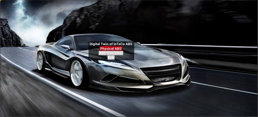
2.2 System design

 There is only one VR application (game) in UE4 that is designed for the user.
There is a “main menu” scene where user chooses the right mode of the game. In case of
this thesis, it should be “ABS simulator” (Figure 7).

 Figure 7. Main menu of the application
 Then there is a transition to the scene with car. The user should be equipped with
VR headset already and sit on in front of Steering Wheel on Logitech G29 equipment.
Using pedals, user can accelerate a vehicle and press the brake. The Steering Wheel of
Logitech G29 rotates the Steering Wheel in the game exactly in the same way.

 UE4 communicates with Logitech G29 through USB interface. With VR headset
it uses USB and HDMI interfaces (Figure 8).

 29
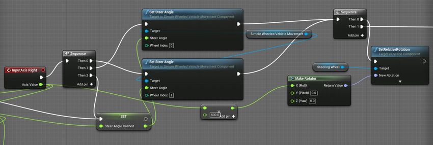
Figure 8. System diagram of connections
 The used control buttons and pedals are assigned in UE4 project. Steering wheel
logic is done using Blueprints (Figure 9). Input data, that comes from Logitech G29
Steering Wheel when wheel is turned, is in range from -1 to 1. If the value is 1, then the
wheel is fully turned on the left. If the value is -1, then it is fully turned on the right. This
number is multiplied by 500 in order to transform it into the degree range. It can be used
then for rotators which can turn the wheels in the simulator in the right rotation position.
UE4 tracks the position of the steering wheel in real-time manner.

 Figure 9. Steering wheel logic section in Blueprint

 30
Figure 10. Decision diagram for Steering Wheel logic

2.3 Car model in Unreal Engine 4

 Before proceeding with the logic, first of all the model of the car should be created.
The model was borrowed from another thesis that is done in TalTech [12]. This vehicle
is accelerated by four wheels at the same time. Each wheel has an ABS logic applied.
When the user brakes, all 4 wheels brake at the same time.

 31
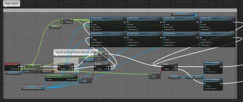
Figure 11. The model of a car
 The logic of it is done in Blueprint called “SimpleWheeledVehicleBP” and the
controls are divided into different sections.

2.3.1 Acceleration of the vehicle

 Acceleration of a vehicle is described in the section called “Gas input”. It takes
the actual value of the pedal from 0 to 1 depending on the pressing force on the gas pedal
on Logitech G29. It is multiplied by “drive torque” variable that equals 1000 in the
project. Drive torque applies on each wheel on the car and the vehicle starts moving.
However, there is limitation and “broken” logic here regarding engine rotation speed. For
some reasons, UE4 does not count engine as an instance properly, but it could be revised
and fixed by adding additional coefficients or fixing the logic.

 32
Figure 12. Whole visual logic of “Gas input” section in Blueprints

 Figure 13. Decision diagram for Acceleration of the vehicle wheels

2.3.2 Brake control of the vehicle

 This is the most important part of the project and, fairly, the most complicated one
because of the connection with ABS logic. It is described in the block called “Brake
input”. The signal comes in the same way as an acceleration input with the same range:
from 0 to 1. “Brake Torque” variable controls the force of braking and it equals 1500 in
the project. This force is applied on each wheel of the vehicle when the braking process
begins. Since it is connected with ABS logic, it is applied when certain conditions are
true depending on the controller that is described in the Section 2.4. The data from the
fourth wheel is transferred to “BP_CarLevelGraphs” Blueprint for building a graph.
 33
Figure 14. Whole visual logic of “Brake input” section

Figure 15. Decision diagram for Brake control of the vehicle

 34
2.3.3 Reversing gear

 If the user wants to change the direction of the movement of the vehicle, he can
press the assigned button for this. Right now it is assigned on keyboard button R, but later
it could be changed to the button or, even, the gear of Logitech equipment.

 Figure 16. Logic for reserving gear of the car

2.4 Model of ABS in Unreal Engine 4

 This section describes how the ABS logic is constructed and how mathematical
model from Inteco is applied in UE4. There are several parts that need to work together
and they will be reviewed step by step.

 Time per tick, that is mentioned in the subsections, equals 0.012 seconds roughly.
This value depends on the performance of PC and how many frames per second in the
game.

2.4.1 Wheel distance measurement

 All the four wheels have the same logic in calculating the distance that they
passed, but there will be taken only one of it for reviewing the logic. The fourth wheel
will be revied in this and next sections regarding the calculations and math modelling.

 For calculating the passed distance in meters, there is a formula (25) used.

 = ∙ ∙ 1000 (25)
 360

 Where
 S – distance passed, m;
 35
L – length of the wheel, km;
 n – number of rotations.

 Length of the wheel can be calculated in the following way in formula (26).

 = ∙ 2 (26)

 Where
 r – radius of the wheel.

 There are also macros used called “Alert Value Change Tracker”. It tracks if the
incoming value is changed. If the new value comes and it is different from previous one,
then old value is decreased by new value. Since it is used on four wheels, UE4,
surprisingly, increases the time per tick and, because of that, the resulting value needs to
be divided by 4.

 Figure 17. Whole visual logic of calculating passed distance by the fourth wheel

2.4.2 Wheel speed measurement

 The speed of the wheel is calculated in the following way in formula (27).

 1
 = ∙ ∙ (27)
 360

 36
Where
 v – speed of the wheel, m/s;
 n – number of rotations;
 L – length of the wheel, m;
 – time per tick, s.

 Please note that, for the same reason as it is described in the previous section 2.4.1,
there should be used the number 4 instead of 1 in converting to seconds.

 Figure 18. Whole visual logic of calculating speed of the fourth wheel

2.4.3 Travel distance measurement

 Vehicle speed calculation starts with getting speed of the vehicle in Unreal Engine
units. Following the documentation, 1 unit in UE4 equals 1 centimetre. The same macro
is used here and it is described in 2.4.1. If the value is changed, the new value is multiplied
by frame rate. Then it is converted to meters and sent to “BP_CarLevelGraphs” Blueprint
for building a graph. The value will be used in the next section 2.4.4.

 37
Figure 19. Whole visual logic of calculating distance of the vehicle

2.4.4 Vehicle speed measurement

 The speed of the vehicle is measured in the following way. The resulting value
from previous section 2.4.3 comes in centimetres/frame rate. It needs to be converted into
meters/second. In order to do that, the following formula (28) needs to be used.

 1
 1 = 2 ∙ 1000 ∙ (28)

 Where
 1 – vehicle speed, m/s;
 2 – vehicle speed from the incoming value from previous section 2.4.3,
 centimetres per time per tick;
 – time per tick, s.

 The resulting value is transferred to to “BP_CarLevelGraphs” Blueprint for
building a graph.

 38
Figure 20. Whole visual logic of calculating speed of the vehicle

2.4.5 Slip coefficient calculation

 Slip coefficient is calculated in the following way. Vehicle speed is decreased by
wheel speed. Then the resulting value is divided by wheel speed. Please, take a note that
slip coefficient is different for each wheel during the braking since it is calculated for
each wheel separately.

 Figure 21. Whole visual logic of calculating slip coefficient

 39
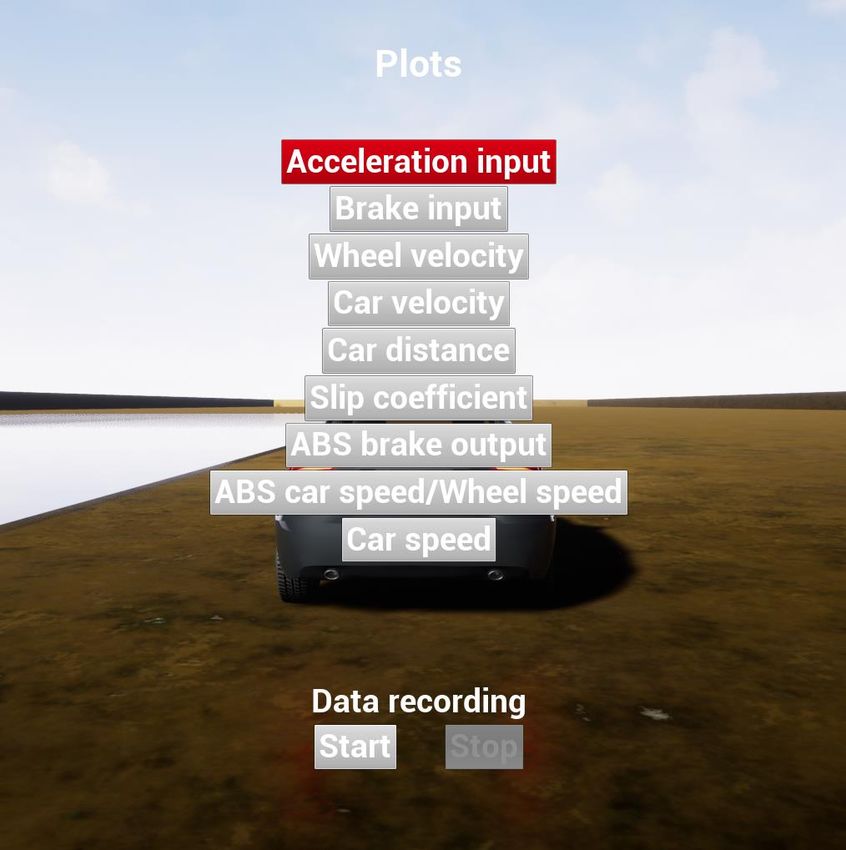
2.4.6 Controller block

 The controller here is very simple and not very well developed, but it is, basically,
a simple trigger that acts as a relay. If slip value is less then higher trigger value (in case
of the thesis project, it is 0.3) and more than lower trigger value (it is -0.3), then it allows
to lock the wheel. When the value goes beyond the limit, then it disables the possibility
to lock the wheel. Each wheel behaves in a unique way depending on the road (surface)
conditions.

2.5 Graphs in UE4

 This section describes how the graphs is drawn in UE4 project.

 All the logic regarding graphs is done in “BP_CarLevelGraphs” Blueprint. At the
moment, the feature can be used with keyboard and mouse only. Later it can be improved
by adding such controls to the buttons on Steering Wheel on Logitech G29. Graph
selection menu can be called by pressing button “P” on keyboard and if the vehicle is
fully stopped. To start drawing charts, “Start” button needs to be pressed and recording
begins. When the ride on the vehicle is finished, data recording needs to be stopped by
pressing “Stop” button. For observing the results, particular graph can be selected if user
is interested in one of the characteristics. There are, overall, 8 graphs available for
observing except ABS brake output (it is supposed to be used in case if Simulink model
that is connected to real ABS laboratory stand communicates with UE4 project which is
not in the scope of this thesis project part).

 All the graphs are drawn in green colour in general. However, when brakes are
applied, the line turns into red colour. It is done for highlighting the braking process and
make it easier for the reader to understand how ABS works. Graphs in the next sections
are done with the same ride except slip graph in Section 2.5.6.

 40
Figure 22. Graph selection menu

2.5.1 Acceleration input graph

 Acceleration graph is build based on the input from the gas pedal. From the graph
below, it can be clearly seen how the user pressed the gas pedal and how much force he
applied on it. As it was described in Section 2.3.1, acceleration range is from 0 to 1. Time
is measured on X-axis in seconds and acceleration input value on Y-axis.

 41
Figure 23. Acceleration input graph sample from the application

2.5.2 Brakes state graph

 Brakes state graph is build based on the state from the brakes of the fourth wheel.
From the graph below, it can be seen how ABS releases the brakes from time to time for
giving a control on the vehicle for the user. As it was described in Section 2.3.2, brake
state could be 0 or 1. Time is measured on X-axis in seconds and brakes state value on
Y-axis.

 42
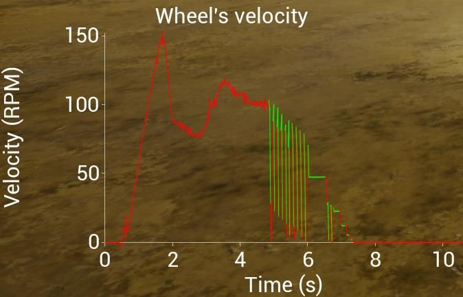
Figure 24. Brakes state graph sample from the application

2.5.3 Wheel velocity graph

 The graph is built based on values from variable “Wheel RPM” that is inside the
block “Wheel speed measurement test (fourth wheel)” in “SimpleWheeledVehicleBP”
blueprint (check section 2.4.2 for more information). Time is measured on X-axis in
seconds and wheel’s velocity value (rotations per minute) on Y-axis.

 43
Figure 25. Wheel’s velocity graph sample from the application

2.5.4 Car’s engine velocity graph

 The graph is built based on values from function “Get Engine Rotation Speed”
from “SimpleWheeledVehicleBP” blueprint. The function is UE4 based. The data seems
not quite right and the limitations are discussed in section 2.3.1. Time is measured on X-
axis in seconds and car’s engine velocity value (rotations per minute) on Y-axis.

 44
Figure 26. Car’s engine velocity graph sample from the application

2.5.5 Travel distance graph

 The graph is built based on values from variable “Vehicle Distance Meters Sim”
that is inside the block “Vehicle distance measurement test (as a whole)” in
“SimpleWheeledVehicleBP” blueprint (check section 2.4.3 for more information). Time
is measured on X-axis in seconds and car distance value (meters) on Y-axis.

 45
Figure 27. Car distance graph sample from the application

2.5.6 Slip coefficient graph

 The graph is built based on values from variable “Slip Coef Sim” that is inside the
block “Slip coefficient” in “SimpleWheeledVehicleBP” blueprint (check section 2.4.5 for
more information). The range of the value is from -1 to 1. Time is measured on X-axis in
seconds and coefficient value on Y-axis.

 46
Figure 28. Slip coefficient graph sample from the application

2.5.7 Wheel speed graph

 The graph is built based on values from variable “Wheel Velocity Meters Sim”
that is inside the block “Wheel speed measurement test (fourth wheel)” in
“SimpleWheeledVehicleBP” blueprint (check section 2.4.2 for more information). Time
is measured on X-axis in seconds and wheel speed value (meters per second) on Y-axis.

 47
Figure 29. Wheel speed graph sample from the application

2.5.8 Car speed graph

 The graph is built based on values from variable “Actual Car Speed” in
“SimpleWheeledVehicleBP” blueprint. It is calculated in the following way: value from
function “Get Forward Speed” is multiplied by 0.036. The resulting value is written in
variable “Actual Car Speed”. Time is measured on X-axis in seconds and car speed value
(kilometres per hour) on Y-axis.

 48
Figure 30. Car speed graph sample from the application

2.6 Analysis of the results

 The application is not ideal, but the goal is reached and there is an environment
and system to work with. The most important achievement is the possibility to apply ABS
on any wheel and it does not matter which vehicle is going to be taken and how many
wheels on it. Thanks to the developments of the vehicle that were done by another student,
it was easier to focus on developing logic for controlling braking process and simulating
ABS.

 Event tick that is used in the project is similar to “fundamental step size” in
Matlab. But Event tick time is dependent on frame rate. For instance, if there are 30 FPS,
then 1 frame lasts roughly 0.03333 seconds (1 frame / 30 seconds = ~0.03333). The “delta
time” value is based on the frame rate and reader should be aware of it while working
with UE4.

 49
3 Summary

 There are two different approaches that are tried to be managed by a team:
hardware-in-the-loop based and full UE4 simulation approaches. There is a trial in the
thesis to do modelling in UE4 without using Matlab and there are achievements in this
case. Firstly, right now it is possible to use ABS on the wheels separately instead of using
the physics of one wheel only. Secondly, there is a possibility to try different road
conditions and surfaces. Observing results in that way is much easier and the development
of an effective ABS controller could be more efficient for the future research.

 The goal of the thesis is reached, but with some limitations. Due to the time
limitation, it is hard to make the project perfect. There is lack of experience in applying
additional physics. The laboratory stand has some issues with sensors from time to time
and, sometimes, the issues could be unsolvable and the only solution could be just waiting
and restarting PC. That makes observing tougher while exhaustive tests and the team
wasted a lot of time because of it.

 The developed application is VR-based. User should use PC, Oculus Rift VR
headset, and Steering Wheel Logitech G29 in order to receive full driving experience.
ABS system is applied on each wheel separately. The vehicle is four-wheel drive car
which means every wheel is accelerated.

 In summary, the result of the thesis is a prototype platform that was developed for
studying the effects of applying the ABS system in driving. Initial tests show that the
system has a good potential for contributing to understanding in improving driving safety
from the perspective of maintaining vehicle controllability when there is sufficient slip
between the wheels of the vehicle and the driving surface using the ABS system. The
driving experience is delivered through a realistic VR environment. This would provide
a good opportunity for investigating the behaviour of drivers in difficult road conditions
[12]. The information for behaviour analysis should be collected by running relevant
experiments which is the next logical step for this research and development effort. For
instance, different surface types or roads could be tried, and the results could be
compared. The application is developed in UE4 meaning that the results are observable
and it is a good possibility for future researchers to develop an ABS controller in virtual
environment.
 50
4 Discussion and Future Work

 There are some issues related to measuring rotation speed of an engine of the
vehicle. It does not work as intended since author has tried to find a solution to control
all the wheels separately. It could be fixed easily by adding coefficients, but it needs to
be investigated.

 In addition, the controller block is not very well developed. Now, it is just a relay
that triggers if the slip value reaches the limits. It can be replaced by proportional-
derivative or proportional-integral-derivative controller in the future to improve the
performance of ABS.

 There is definitely the possibility to add more surfaces for the tests and develop
scenes with different dangerous situations. It would add more user experience and it will
increase the meaning of using ABS instead of hard locking the wheels.

 Of course, four-wheel vehicle is not the limit here. ABS can be developed for
other vehicles such as motorcycles, planes etc. In this thesis all the four wheels have ABS,
but it can be applied on any wheel and disabling ABS on one of the wheels will lead to a
different experience.

 Mechanical side of the vehicle is not very well investigated and it could be
calibrated through UE4 features such as Blueprints. The whole project is developed using
Blueprints, but there is a possibility to improve physics or logic through coding using
C++. So, developing the libraries for the project, instead of using macros or constructors
in Blueprint, would be a way to go.

 51
5 References

[1] H. R. More and A. A. &. W. A. V. Digrase, “Linear PID control technique for
 single wheel ABS (anti-lock braking system) of motorcycle,” in 2017 2nd
 International Conference for Convergence in Technology (I2CT), 2017.
[2] A. Rasheed and O. &. K. T. San, “Digital Twin: Values, Challenges and Enablers
 From a Modeling Perspective,” vol. 8, pp. 21980--22012, 2020.
[3] J. Tham, A. H. Duin, L. Gee, N. Ernst and B. &. M. M. Abdelqader,
 “Understanding Virtual Reality: Presence, Embodiment, and Professional
 Practice,” vol. 61, pp. 178-195, 2018.
[4] Z. &. Y. Z. Taixiong, “Development of hardware-in-loop and virtual reality co-
 simulation platform for automotive anti-lock braking system,” in IET
 International Conference on Information Science and Control Engineering 2012
 (ICISCE 2012), 2012.
[5] S. &. W. H. Xu, “The research and analysis of the efficiency of automobile ABS
 brake based on fuzzy control,” in 2012 2nd International Conference on
 Consumer Electronics, Communications and Networks (CECNet), 2012.
[6] Z. &. X. G. Wei, “An ABS Control Strategy for Commercial Vehicle,” vol. 20,
 pp. 384-392, 2015.
[7] Inteco, “ABS Antilock Braking System,” Inteco, 1999-2021. [Online]. Available:
 http://www.inteco.com.pl/products/abs-antilock-braking-system/. [Accessed 5
 May 2021].
[8] Epic Games, “Unreal Engine,” Epic Games, 2004-2021. [Online]. Available:
 https://www.unrealengine.com/en-US/. [Accessed 5 May 2021].
[9] L. Ye and C. &. C. J. Feng, “When Green Screen Meets Panoramic Videos: An
 Interesting Video Combination Framework for Virtual Studio and Cellphone
 Applications,” vol. 8, pp. 2337-2347, 2020.
[10] Epic Games, “Oculus Rift Quick Start,” Epic Games, 2004-2021. [Online].
 Available: https://docs.unrealengine.com/en-
 US/SharingAndReleasing/XRDevelopment/VR/OculusVR/OculusRift/QuickStar
 t/index.html. [Accessed 5 May 2021].
[11] O. Ille, ABS System Control, Tallinn: Control lab, 2014.
[12] Chaudry and A. Jawad, Human Behaviour in VR: Special Automotive Based
 Environment, Tallinn: TalTech, 2020.
[13] Inteco, ABS The laboratory Anti-lock Braking System User's Manual, Tallinn:
 Control Lab.
[14] MathWorks, “MATLAB,” MathWorks, 1994-2021. [Online]. Available:
 https://www.mathworks.com/products/matlab.html. [Accessed 5 May 2021].
[15] J. Steuer, “Defining virtual reality: Dimensions determining telepresence,”
 Journal of communication, vol. 42, pp. 73-93, 1992.
[16] Oculus, “Oculus Rift,” Facebook, [Online]. Available:
 https://www.oculus.com/rift/. [Accessed 5 May 2021].

 52
You can also read