2019 2020 Team Description Paper RFC Cambridge
←
→
Page content transcription
If your browser does not render page correctly, please read the page content below
2019 - 2020 Team Description Paper
                    RFC Cambridge

      Kendall Zhu, Coleman Hooper, John Keszler, and Katrina Gonzalez

        Harvard University, Cambridge MA 02138 hurcofficial@gmail.com

       Abstract. This paper overviews the main systems of RFC Cambridge,
       a small-sized league (SSL) team intending to participate in RoboCup
       2020 in Bordeaux, France. Since our previous TDP in 2016, the team
       has undergone a rebuilding period due to a significant decrease in the
       number of team members. Many of the designs described in this paper
       were motivated by these constraints, so we hope they can be useful for
       smaller or new teams trying to enter the SSL. Mechanically, we have
       shifted to a simpler chassis design with a modified kicker configuration
       to support larger brushed motors. For the electrical system, we have
       switched to an ARM MCU based system (Teensy) as well as upgrading
       our kicking circuitry with feedback control and safety systems. Finally,
       we have rewritten a simple arduino-based firmware layer from scratch,
       and rebuilt our software code base in Python to facilitate on boarding
       and accessibility for new members.

1     Mechanical System

1.1   General Overview

Personnel constraints over the last few years have pushed us to simplify our
mechanical systems, particularly by introducing brushed motors to our robot
design. Despite lower performance specs, brushed motors alleviate control diffi-
culties (particularly direction-switching) that the team was struggling to over-
come with brushless motors. We hope this may be useful to newer teams who
would prefer easier and less expensive motors to begin with.

1.2   Chassis and Motors

Since competing in 2016, we switched from using brushless motors to brushed
20.4:1 Pololu metal gearmotors. We found that the motors that we had been
using previously often broke after very little use due to internal gear stripping.
Due to the previous design using external gears, we also had problems with gear
slippage, which were solved by switching to direct drive. We also switched to
using brushed motors as the driving circuitry was significantly easier to imple-
ment as our old brushless motor system faulted out frequently which did not
allow for fast, instantaneous direction changes, but our new brushed motors do
2       Kendall Zhu, Coleman Hooper, John Keszler, and Katrina Gonzalez

allow us to change the direction quickly. The change to brushed motors signif-
icantly lowered the barrier to entry for our team to make a functioning robot
and we recommend any new team to consider brushed motors before switching
to brushless.
    Since we switched the motors used, we also needed to adjust the chassis in
order to accommodate the now longer motors, as well as the larger omniwheels
that attach to them. We fabricated the two chassis plates out of 1/4 inch acrylic
that we laser cut. We chose acrylic as it allows rapid prototyping of different
designs, while also being durable enough when 1/4” is used. We used generic
hex standoffs between the two chassis plates to allow for enough vertical spacing
to accommodate our components. Again, using various combinations of standoffs
to modulate the height of the chassis allowed us to create a flexible design that
we could change easily just by adding or removing a few standoffs or washers.
The motors themselves are placed on the bottom plate to give the robot a low
center of mass.
    This season, we also intend to re-thermoform our helmets in order to better
accommodate any size changes between different iterations of our chassis. We
opted for thermoforming, since our team is relatively new, and would currently
like to stay flexible to accommodate changing designs.

Fig. 1. Onshape rendering of chassis and motors, as well as kicker and basic dribbler.

1.3   Kicker

Our current kicker uses a solenoid, with a 3D printed extension made of PLA.
We have found that printing the extension piece with maximum infill makes it
durable enough to run for extended periods of time without replacement. Since
we are using brushed motors, we face a very tight size constraint between the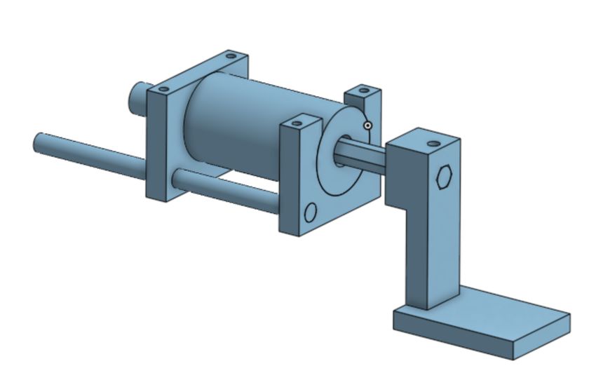
2019 - 2020 Team Description Paper RFC Cambridge             3

two chassis plates on the robot. Therefore, we attached our kicker to the top
plate rather than the bottom. The dribbler is located in front of the kicker.

Fig. 2. Current kicker design. The solenoid is attached to the top plate with screws on
the top. The extension piece that makes contact is printed using PLA with maximum
infill for durability.

    In the longer term, we hope to accommodate for chip-kicking as many suc-
cessful teams have done. We plan to experiment to use a linear stepper motor
such or slider-crank mechanism to modulate the height at which the kicker con-
tacts the ball. This along with a wedge-shaped kicker, may allow us to contact
the ball at different heights to control the type of kick. Many teams have im-
plemented successful chip-kickers through using two dedicated solenoids; with
our current design, we do not have the space in order to insert another solenoid
[Bis+13].

1.4   Dribbler
We are currently experimenting two dribbler designs - one with spiral grooves
with spacing from 2-5mm, and another with a conical shape with edges twice
the radius of the center portion in order to better center the ball.
    We manufactured our dribblers by 3D printing a mold with 100% infill. This
prevented silicone from seeping into pockets in the mold during the vacuum
process. We then allowed the dribbler to cure in its mold overnight.
    We are also testing a few different types of silicone for the dribbler, with dif-
ferent mechanical properties. We found that using softer silicone is advantageous
in the case where the dribbler contacts the ball at a higher point as the extra
give helps absorb passes and prevents the ball from bouncing too much when we
move quickly, but we have yet to finalize this design.
    At the moment, we are trying to change our power transmission scheme
from the dribbler motor to the dribbler itself. We currently use two pulleys and
a rubber band. Using a rubber band allowed us to change the design of our
4 Kendall Zhu, Coleman Hooper, John Keszler, and Katrina Gonzalez
dribbler frequently (i.e. the distance between the motor and the dribbler shaft)
which helped with initial prototyping speed and cost. Therefore, it could be
beneficial for new teams to start with this design. However, now that we have
finalized the basic design of our dribbler, we intend to switch to a geared system
in order to reduce power losses, quickly prototype at different speeds and torque
to determine our optimal parameters, and create a more robust dribbler.
Fig. 3. Dribbler and kicker assembly.
2 Electrical
2.1 Kicking and Motors
We upgraded our kicking circuitry with additional safety features this year. Our
main objective was to make sure the robots were safe for new users, as our
revived Robocup group had recently accepted a large influx of new members,
the majority of whom would be working on software.
1. We added automatic discharging of the kicker capacitors when the robot is
turned off using a circuit built into the PCBs. The robot will slowly discharge
automatically unless a software pin is active.
2. We added feedback control into the charging DC-DC converter circuitry in
order to control the charge level. This provided more fine-grained control of
charge level and better safety when debugging robots on the field.
Our new kicking circuity is based on the LT3750 3750 Capacitor Charger
Controller, inspired by the design used by Georgia Tech’s Robojackets [Alm+18].
The system charges up 2x 250V 3500uF capacitors mounted on the top side of
the PCB. The new feedback control system allows us to charge and discharge2019 - 2020 Team Description Paper RFC Cambridge 5 the capacitor to the desired voltage range with an uncertainty of ±1V in ap- proximately 7 seconds or less. As we switched over to brushed motors we also switched to H-Bridge motor controllers (VNH5019) which gave us added current sense feedback (which is an analog voltage proportional to the motor current). The H-Bridge controllers also provided built-in reverse-voltage, over-voltage, and over-temperature protection. 2.2 Interfacing A major architectural change we made was upgrading to an ARM based mi- crocontroller unit (MCU) platform from a Atmega based system by switching to a Teensy 3.6 MCU. The primary reason for this switch was accessibility and flexibility, as the firmware for the Teensy is developed using the Arduino Inte- grated Development Environment (IDE), which is a much higher level tool than Atmel studio. The included libraries make interfacing with sensors and using protocols like I2C much easier. We did optimize many of the existing library functions that were slow, but we knew we wanted to run most of the high level and more computationally difficult algorithms on the server side (see Section 3). The Teensy platform also gives us the ability to develop, update and debug our firmware quickly and efficiently. Even with the minor reduction in firmware efficiency, the ARM core on the Teensy is so much faster that we have the ability to do a lot more in firmware than we previously expected, which is why we are able to perform PID calculations and encoder feedback directly on the Teensy (see Section 2.4). Having an increased number of hardware interrupts also allows us to manage the motor encoders directly from the MCU. 2.3 PCB Updates Along with the previously mentioned additional circuitry, we also switched to a 4 layer PCB design, with the internal 2 layers designed only for power delivery. This change was made to account for the added current draw of the new motors and the kicking system, as well as to decrease any inefficiencies due to unneces- sary resistance from longer traces. Beyond these changes, we added more easily removable connectors and cables rather than soldering everything to make it easier and faster to switch out components, allowing for rapid prototyping and comparisons when developing and testing various components. Figure 4 shows our PCB layout along with annotations that outline the function of different sec- tions of the board. The circuit layout design was done using EAGLE CAD. The top half of the board is reserved for all the high voltage circuitry. The bottom half includes the Teensy, motor drivers, and power regulators, which is currently just 2 linear regulators that provide 3.3v and 5v power. Our system is powered by a 3 cell 4000 mAh Li-Po Battery. The motors and kicking circuitry are run directly off the 12V power line from the battery. Our PCB separates the ground planes (which are on the internal layers of the PCB) for our 12v and 3.3v / 5v power supplies to avoid any noise from the DC/DC converter of the kicking circuitry. We added I/O multiplexing ICs since we have a fair amount of digital
6       Kendall Zhu, Coleman Hooper, John Keszler, and Katrina Gonzalez

logic that are connected to various signal wires and status LEDs, which could
not all be individually connected to the Teensy. While the Xbee radio system is
on the top half of the board with the kicking circuitry, the power and ground
planes (for both the high and low voltage rails) do not extend under it to avoid
radio interference.

                             Fig. 4. EE block diagram

2.4   Firmware

Our firmware is designed to abstract out basic robot commands (motion, dribbler
on/off, charging, and kicking) so that the software can send desired commands
at a higher level of abstraction, and the firmware will convert these higher-level
commands into the hardware signals for individual actuators.
    The firmware-level motion control uses a built-in Arduino PID controller to
set the speed of each motor. The motion control procedure uses the Arduino
library FastPID to assign power values to the motor pins. These power values
are based on input setpoint velocities and the encoder readings for the current
speed in ticks per second. Our firmware code can be found on our public Github.
    The resolution of the encoders proved to be a limiting factor for speed control,
since we found that PID updates needed to happen at intervals of less than 5
milliseconds in order to be accurate. Our current encoders provide around 1000
effective ticks per revolution, which is barely sufficient for smooth speed control.
Therefore, we hope to upgrade our encoders in the near future. We would like to
2019 - 2020 Team Description Paper RFC Cambridge 7
Fig. 5. PCB layout
acknowledge the ZJUNlict robocup team for inspiration in designing our motion
control firmware. Their open source firmware code helped us understand how to
use encoder tick readings and timer interrupts to implement PID speed control.
[Hua+19]
The firmware is also responsible for charging and discharging the capacitors,
which it currently does via time estimation. Since we have the available circuitry
to read the current charge level, in the future we plan to switch to controlling
charging and discharging the capacitors using the measured charge level.
3 Software
We have made major changes to our software stack since we last competed. We
originally had a large codebase in C# that whilst effective, presented a large bar-
rier to entry for the new members of the team, especially as prevalence of C#
had decreased substantially since we last competed [Ans+16]. Furthermore, ev-
ery team member with working experience in the previous codebase had already
graduated. Because of this we decided to switch to a new software stack.
Our goals when searching for a new stack in order of priority were:
1. Low barrier to entry: We wanted newer members of the team to be able
to use as much of their previous programming experience as possible. This
meant trying to avoid any uncommon programming languages or tools. It
also had to be easy for new members to get their development environment
setup - we didn’t want new members to spend their first team meeting bat-
tling through horrific linking errors for example.8 Kendall Zhu, Coleman Hooper, John Keszler, and Katrina Gonzalez
2. High speed of iteration: We wanted to be able to try new things and
iterate our codebase quickly. We didn’t want a codebase that was either
(a) extremely verbose, where making a small change could involve writing
thousands of lines of code, or (b) extremely abstract where it is hard to
understand what functionality is implemented where.
3. Availability of libraries: We wanted to have all relevant tooling available
in the same language, without have to negotiate an interface between two
programming languages which would just add additional complexity. We
needed to be able to do both low level operations (receiving packets from
the refbox for example) and also be able to run high level algorithms and
machine learning frameworks.
We concluded the only programming language that fit our requirements was
Python. We experimented with Georgia Tech’s RoboJackets codebase which
worked well, however having over 20000 lines of Python and 20000 lines of C++,
we concluded the barrier for entry was simply too high for our needs.
We decided that we would write the firmware for our robots in C/C++ in
order to run on our Arduinos and then write our own codebase from scratch in
Python for the rest of our software. This included a new custom built simulator
(which is discussed in a later section). Our codebase so far is around 5000 lines
of code. We don’t anticipate the completed product to be more than 10000.
Our full software is available on GitHub, but we will highlight our key design
decisions and findings below:
3.1 Multiprocessing
Due to Python’s Global Interpreter Lock (GIL) design, implementing shared
memory parallelization (using the multithreading module) was not going to
be a viable solution for our needs. For multiple compute bound tasks, running
with the multithreading module provides almost no benefit (as only one process
can hold the GIL at a time). Whilst some tasks (such as waiting for Protobuf
messages from the refbox) may not be compute bound, a large number of them
would be (the simulator, the actual control tasks etc.) and so we realized that
shared memory parallelization wasn’t going to be possible.
We opted to use the multiprocessing module to run each task in a separate
process that communicates back to the central Coordinator process through
the multiprocessing.Queue abstraction (which is a wrapper around a UNIX
pipe). Each process has two Queues (pipes), one for receiving the latest game
information from the coordinator and one for writing information back to the
coordinator. The central coordinator process receives information from all of the
tasks that are currently running (in separate processes) and incorporates this
information into its source of truth for the game. It then publishes this source
of truth game state back out to all of the other tasks. See figure 6.
This architecture seems to work well so far, with the coordinator pushing
information to each provider around at around 100Hz (meaning a typical delay2019 - 2020 Team Description Paper RFC Cambridge 9
between one task publishing something and another task seeing it of around 0.01
to 0.02 seconds.
Fig. 6. Software Architecture
3.2 Decision Making
Desired robot actions are determined by a control loop in the strategy process.
For each robot, the strategy module can set waypoints, and turn on/off charging,
dribbling, and kicking. We have organized our strategy code into five loosely
defined abstraction layers:
1. Actions: Self-contained procedures. These include basic path planning using
RRT [LaV98], pivoting around a ball, and kicking.
2. Routines: Multi-phase actions such as approaching and dribbling the ball,
charging then shooting towards a target.
3. Roles: Single-robot role logic such as ”goalie” or ”striker” that evaluate the
state of the game and assign routines or actions based on conditions.
4. Play: Reusable multi-robot role assignments to address specific scenarios (i.e.
forming walls)
5. Coaches: High level classes for playing full matches - a coach must include (or
inherit) handlers for all the possible referee commands, such as kickoff, force
start, and free kicks. For each scenario, the coach runs a play or performs
dynamic role assignment for all robot IDs on the team.
As a result, the strategy module has a loosely defined state-machine archi-
tecture where it must evaluate the state of the game at any frame and give
the desired commands. At the moment, any function within the aforementioned
hierarchy may be invoked from the top level of the strategy control loop.
Before being sending commands to a robots, the software calculates the mo-
tion vector pointing towards the robot’s next waypoint. The algorithm uses the
maximum robot speed until the robot is within about 20 centimeters from its
waypoint at which point slows down to a value proportional to the distance to
travel. It also takes into account the direction of future waypoints, by slowing
down less if the angle is closer to 180 degrees. If there are multiple waypoints10 Kendall Zhu, Coleman Hooper, John Keszler, and Katrina Gonzalez
and the robot has come within a threshold distance of the first, that waypoint is
removed. These threshold constants and the slowdown equation, shown below,
will need to be further tuned based on real world performance.
Slowdown = M ax(0, 1 − θ/(π/4))
Where 0 ≤ θ ≤ π is the absolute angle in radians between the current motion
vector, and the vector from the first waypoint to the next. This means that turns
sharper than 90 degrees will receive full slowdown proportional to distance as
the robot approaches it, while points aligned with the following waypoints will
not invoke any slowdown.
3.3 Simulation
We created a custom simulator that can simulate basic physics such as collisions
and ball friction, as well as robot actions (movement, dribbling, and kicking). The
simulator is designed to enable offline prototyping, by replacing both the vision
provider and the radio provider in the modular setup. The simulator pretends
we have a full team of robots operating under ideal conditions. Although it
cannot model the real world fully, it has been useful for testing state machine
logic and strategic evaluation. (Furthermore, combining its use with a custom
visualizer has given us more flexibility than adopting an existing simulator such
as GRSim). So far, rudimentary handling of the following items have provided
enough realism for basic prototyping:
1. Ball Friction: The simulator estimates the ball velocity from historical
timestamped positions stored in the gamestate, and assumes that the ball
will continue in the same direction with constant deceleration. We found that
inferring ball velocity from two past data points must interpret the change in
position as the velocity at the midpoint of those two timestamps. Otherwise,
applying deceleration across many small timesteps (as the simulator does)
will not give accurate results.
2. Robot Collision: We do a frame-based check of each robot, and move over-
lapping robots away from each other by equal amounts to resolve collisions.
3. Ball collision: In each frame, when the ball intersects with a robot we move
the ball outside the robot, and preserve the component of its velocity that
was tangent to the robot model (which is a circle with a flat front face).
4. Robot Movement: Each robot moves at exactly the speed of the given
vector command. (Note: this results in slower convergence to waypoints than
in real life, so we hope to improve this model by incorporating acceleration
limits)
5. Dribbling: We model dribbling by moving the ball towards the center of
the robot when it is within a small distance of the robot’s dribbler location.
There is a threshold speed above which the ball is not dribbled, to avoid
unrealistic capturing of the ball.2019 - 2020 Team Description Paper RFC Cambridge 11
6. Charging + Kicking: Robots given command to charge will simulate in-
creasing charge level. When given the command to kick we apply a velocity
to the ball in the direction of the robot, if it is in a small radius of the kicker.
Fig. 7. Simulation running with Pygame Visualizer
3.4 Visualizer
The visualization displays robots as colored circles reflecting the simulator’s
model of the robot shape. Other information is displayed graphically, such as
charge level, dribbler status, Robot IDs and waypoints. These elements are drawn
using basic functions from the Pygame API.
Our choice to use Pygame was to allow for custom information display while
minimizing application complexity. Since both the simulator and visualizer exist
in our codebase, we no longer have to deal with vision packet protocols when
prototyping offline. We can also easily visualize any strategic information as we
develop, by adding a few lines of python into the visualizer. Finally, Pygame
allows us to take user click inputs, which we store in the gamestate to enable
manual robot command entry, and virtual ball placement (including click+drag
to apply velocity) when the simulator is active.12 Kendall Zhu, Coleman Hooper, John Keszler, and Katrina Gonzalez
We had some cross-platform compatibility issues, but were able to run Pygame
successfully on Linux, Windows and Mac with Python version 3.7.5/3.8.1 (for
Mac).
4 Future Updates
4.1 Mechanical
Before this coming competition, our main priority is to remake the helmets on
the robots such that they slide on and off easily without rotating. This is to
prevent the robot orientation data from becoming skewed during competition.
4.2 Electrical
One of the improvements we have been working on adding is a IR break-beam, so
that we can more accurately detect if we have captured the ball or not. The only
camera system based approach is frequency inaccurate so with the break-beam
we will be able to definitively tell exactly when we have the ball.
Another improvement that we are looking at making on our PCB is using
switching regulators instead of linear regulators. Switching regulators would not
only be more efficient (which would allow us to remove the heat sinks on our
regulators), but would also be able to provide more current to our 3.3 V and 5
V rails which would allow us to potentially add additional sensors and devices.
We are also looking at developing an FPGA based driving solution for brush-
less motors. While our current brushed motors work great, we know that brush-
less motors could offer high efficiencies and better performance, which we hope
to achieve while also having instantaneous turning with this new system. We
did experiment with using existing brushless motor driver ICs, as well as com-
mercially available electronic speed controllers (ESCs), however the issue with
both of these implementations is that neither allows for instantaneous chang-
ing of direction, which is essential to having a fast, reactive system. Currently
our brushed motors with our H-Bridge drivers do allow this, however they are
limited in performance due the efficiency loss with the brushed design.
4.3 Software
For communications with the robots, we send messages to on board Xbee radios,
which are parsed in the firmware loop. Because we observed that the radio was
unable to send messages or at a high rate (at more than 10 short messages
per second, they would risk buffering and taking a long time). Therefore, we
created a serialization for all 6 robots commands into a single message, so we
can broadcast the single message once for the whole team. However, this is
very limiting in terms of the amount of information we can send. In the future,
we hope to investigate possible improvements to enable higher bandwidth and
sending back sensor data to the software system (i.e. on board sensor-based ball
detection).2019 - 2020 Team Description Paper RFC Cambridge 13
We also noticed that the vision data for the ball is noisy, and hope to in-
corporate a linear Kalman Filter as other teams have done. This would improve
our ability to predict the trajectory of the ball, which is crucial in gameplay.
5 Open Source
Our team has our firmware and software, including our simulator, on Github
as open source. These can be found in our organizational account1 . We plan on
making our mechanical and electrical design documents open source as well by
migrating them from Onshape to a synced location on Github as well.
References
[LaV98] Steven M. LaValle. “Rapidly-exploring random trees : a new tool for
path planning”. In: 1998.
[Bis+13] Joydeep Biswas et al. “CMDragons 2013 Team Description”. In:
2013.
[Ans+16] Eric Anschuetz1 et al. “2016 RFC Cambridge Team Description Pa-
per”. In: 2016.
[Alm+18] J Almagro et al. “RoboJackets 2018 Team Description Paper”. In:
Georgia Institute of Technology (2018). url: https://ssl.robocup.
org/wp-content/uploads/2019/01/2018_TDP_RoboJackets.pdf.
[Hua+19] Zheyuan Huang et al. “ZJUNlict Extended Team Description Pa-
per for RoboCup 2019”. In: arXiv e-prints, arXiv:1905.09157 (May
2019), arXiv:1905.09157. arXiv: 1905.09157 [cs.RO].
1
RFC Cambridge Github Account: https://github.com/rfccambridgeYou can also read