Operating, Maintenance, Servicing and Installation Guide - style, security, innovation...
←
→
Page content transcription
If your browser does not render page correctly, please read the page content below

style, security, innovation...

  Operating,
  Maintenance,
  Servicing and
  Installation
  Guide

watch AlluGuard online at:
www.thegaragedoorchannel.co.uk
Contents
                 Welcome                                                                                  page 3

                 Looking after your garage door                                                           page 4

                 Operating instructions                                                                   page 5

                 Safety                                                                                   page 6

                 Power failure                                                                            page 6

                 Troubleshooting                                                                          page 7

                 Door Service & Safety Check                                                              page 8

                 Service & Maintenance Record                                                             page 9

                 Installation Manual                                                                      page 10

                 Declaration of Incorporation                                                             page 25

                 Ec Declaration of Conformity                                                             page 26

                                     style, security, innovation...

    AlluGuard Limited
    Rotherham Road, Parkgate, Rotherham S62 6FP
    t: 01709 529 723
    f: 01709 524 577
    e: info@alluguard.co.uk
    w: www.alluguard.co.uk
    AlluGuard reserve the right to alter specifications to design and manufacture without notification.
    All specifications are correct at time of publication, errors and omissions excepted. August 2019

2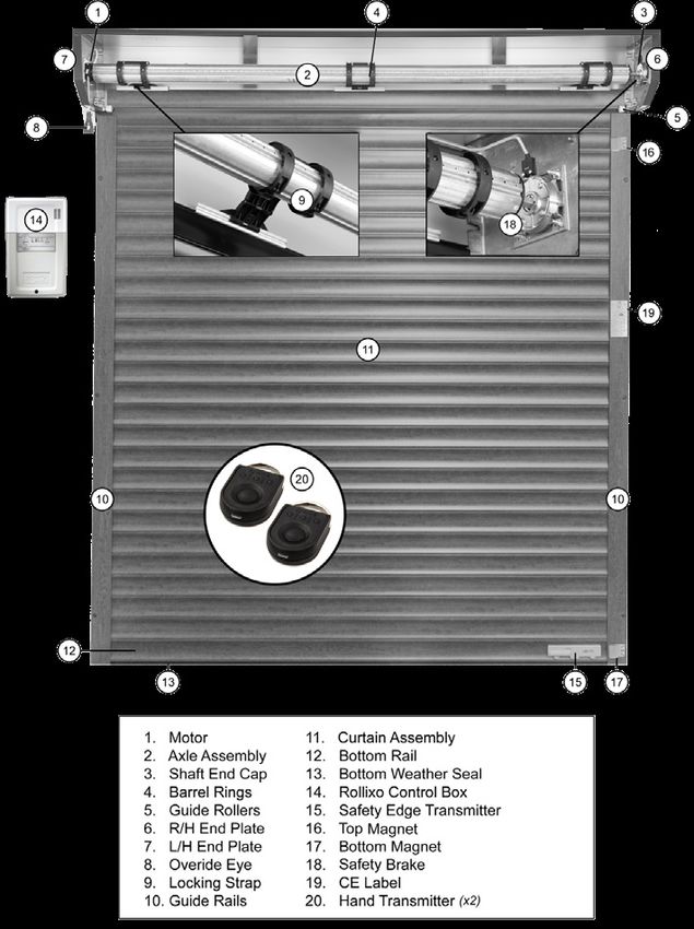
Combining great design and exceptional build               Trusted and quality
quality the AlluGuard 77 or AlluGuard 55 roller garage
door you have purchased has been designed and
                                                           assured
manufactured in the UK and offers attractive, effortless   AlluGuard’s reputation is built on
protection for your home.                                  quality and we are independently
                                                           certified to prove that our quality
We understand that the purchasing of your AlluGuard        management systems are industry
77 or AlluGuard 55 roller garage door is a significant     acknowledged! Our products are
investment for you and your property, this has led us      designed to give you the ultimate in
to putting together this small guide to allow you to       performance ensuring that you’ll be
get to know your garage door better.                       happy to recommend AlluGuard.

Your newly-installed product should give you many          Safety always comes first at
years of trouble-free service with the appropriate         AlluGuard. All our products carry a CE
maintenance and servicing as outlined in this booklet.     mark and have been independently
In order to prolong the life of your door and to reduce    tested for safe operation and
the likelihood of problems please adhere to the            compliance with legislation to EN
following instructions. Please note all products should    13241-1.
only be operated by trained users. Any maintenance
should only be carried out by trained garage door
installers, a list is available from AlluGuard.

Wishing you many happy years with your new                              MANAGEMENT
                                                                          SYSTEMS

                                                              14/5366
purchase.

The AlluGuard team
                                                                                                    3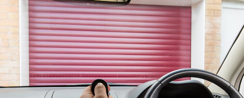
Looking after your
    garage door
                                                                         Additional information
    Tips on maintenance for your new AlluGuard 77 and
    AlluGuard 55 Garage Door.                                            for electrically
    Your garage door is low maintenance:
                                                                         operated products
    ✓ The curtain needs wiping with a damp cloth and a mild soap        Your door should run smoothly and
       to remove any excessive dirt/grime to maintain its appearance     easily as the motor is not designed to
       and to reduce the risk of the surface being damaged.              over-come problems of a badly running
                                                                         or damaged door. If necessary contact
    ✓ This must be done at least monthly in a salt air coastal
                                                                         your approved installer for repair.
       environment.
    ✓ Marks on the paint finish can be cleaned with warm soapy          The motor should be stopping on the
       water and polished with car polish.                               limits and not over-running when the
    ✓ DHF guidelines on visual appearance of newly installed            door hits the floor or the open stops.
       garage doors states that, for a warranty to apply, “The quality
       check should be carried out in natural daylight, not direct       N.B. Always isolate the power before
       sunlight. Stand at a distance of 3 metres from the door to        attempting to make any adjustments or
       view the overall appearance. The door is acceptable if, taking    repairs. Untrained users are advised to
       into account the facts below, none of the following is readily    contact an approved installer.
       visible on the face of the door:
          •    marks or distortion associated with the manufacturing
               process.
          •    minor indentations, marks or scuffs on the surface.
          •    paint or stain blemishes.
    ✓ Chips in the paint work should be touched up to prevent
       corrosion of the metal.
    ✓ The power to the garage door should be isolated before
       washing or repairing the paintwork.
    ✓ The motor and curtain have been designed to be lubrication
       free so you must not oil or grease the guide rails.
    ✓ Make sure no foreign items get collected in the guides i.e:
       stones, sticks, paper etc.
    ✓ Make sure foreign objects are not embedded into the safety
4      edge rubber.
Operating
Instructions
Electrically Operated Products
Under UK Legislation the garage door should be
operated when it is in view (unless fitted with
additional safety equipment e.g. for smart phone
operation), making sure it is not obstructed. Ensure
when the door is running, that you and any other
person stands clear of the curtain and keeps hands
etc. away from the moving parts. Children should
not operate the door or play nearby an opening
door.

Control Unit
Please note the front of the control unit should
only be removed by a trained engineer. Your
garage door can be activated by pressing and
                                                                                      Somfy
releasing the buttons on the front of the control
unit, the button on your remote handset, or a
separate wall switch that you may have installed.

Hand Transmitters
The transmitters are fitted with four buttons and
when any button is pressed the LED illuminates.
The buttons on remotes can be programmed to
suit your requirements (dependent on handset
type). The default setting is one button operation
that allows you to lift, stop and close the door.
                                                        Press & let go
PLEASE NOTE
When opening or closing the garage door you
must monitor the product until it has completed
its operation. If the product is fitted with a safety
device this could be activated during its operation
which would cause the door to stop and reopen a
short distance leaving the door partly open.
                                                                         Press & hold
Batteries                                                                This type of operation is
                                                                         required for “dead man
The expected life span of batteries is 2 years;                          mode”, see the note*** at
however high usage of the door will lead to a                            the foot of page 7 for an
decrease in this.                                                        explanation of its use.

Batteries are not covered under warranty.

                                                                                                     5
The safety edge also works as a weather seal,
    Safety                                                   designed to be pressed against the ground. The
                                                             bottom slat transmitter\cable has an IP rating
    Safety edge                                              of IP54 and is protected against dust and water
                                                             splashing.
    The Safety Edge is fitted to the bottom of the
    door and is activated when the door starts to
    close. If it comes into contact with an object while
                                                             Safety Devices
    the door is closing, it transmits a signal to the wall   The standard remote control receiver unit is
    mounted control unit, the door will then stop and        supplied with either an electrical wireless safety
    reopen a short distance.                                 edge or optical wired safety edge.

    Power Failure                                                To operate:
                                                                 Hold crank handle in
                                                                 line with eye and rotate
    Electrically Operated Products                               handle until the door
    If your roller garage door is not working                    reaches the
    correctly please contact your installer for                  open/closed
    assistance. N.B: Always isolate the power before             position.
    attempting to make an adjustment or repair.
    Untrained operators are advised to contact an
    approved installer.

    Power failure                                                To operate:
    In the event of disruption to the power supply,              Externally fitted doors will need
    or the motor temporarily over heating (the                   the cover cap or
    motor is protected by a thermal cut out), the                override lock removing
                                                                 and the crank handle inserting.
    door can be operated manually. Isolate power
                                                                 Rotate
    supply before using the manual override.                     handle until the
    To operate: Hold crank handle in line with eye               door reaches
    and rotate handle until the door reaches the                 the open/closed
                                                                 position.
    open/closed position.

    If the door is not used during the power
    failure then no action has to be taken as
    the unit will reset itself when the power is                 To operate:
    restored.                                                    Remove lock and insert crank
                                                                 handle and rotate until door
    Important                                                    reaches the open/close position.
    If the garage has no service door then an
    exterior release kit should have been fitted
    to allow emergency opening from outside.
    Follow instructions supplied with that kit.

    Note
    When closing the door manually ensure that the
    locking joints are set in the fully closed position to       DO NOT OVERWIND
    ensure security.                                             When the main power is reinstalled, ensure
    Insert the hooked end of the winding handle into             that the power isolator is switched back on.
    the override eye; this is projecting downwards from          If applicable secure the handle back onto the
    the drive motor at one end of the curtain roll, rotate       wall. Remember to keep the crank handle in a
6   the handle to operate the door to open or close.             convenient place.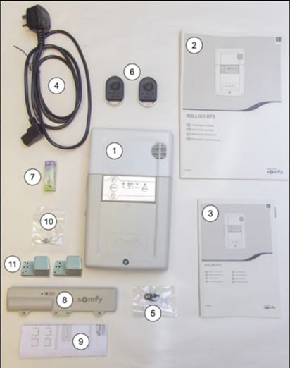
Somfy Technical Assistance - 0113 391 3014
Troubleshooting                                                        Electrically Operated Products

 Fault                                            Possible Cause                                   Solution
  Key fob transmitter not working                Batteries flat                                  Change batteries*
  Bottom slat transmitter not working            Batteries flat                                  Change batteries**

  Door closes but immediately                    Check guide magnet position                     Refit magnet
  re-opens                                       Check the safety edge transmitter is            Reset safety edge transmitter
                                                 turning off at the magnet
  Door only comes down partially before re-      Safety edge hitting obstruction                 Remove obstruction
  opening slightly                               Safety edge fault                               Test safety edge

  Door will open but only close in dead man      Safety edge transmitter not showing any         Change batteries in bottom slat
  mode***                                        lights                                          transmitter**
                                                 Safety edge faulty                              Call installer for advice

  False alarm activation                         Check the safety edge transmitter is            Reset safety edge transmitter
                                                 turning off at the magnet                       Check magnet position

  Door does not operate                          Electrical Fault                                Check electrical supply to unit then press
                                                                                                 hand set button again
                                                                                                 Seek advice from installer

  Drive motor operates but door does not         Detachment of the rigid links                   Ensure rigid links are still attached to the
  move                                                                                           door
                                                 Check mechanical brake                          Try door with manual winder

  Key fobs work but no operation using control   Set in Holiday mode                             Reset unit
  panel                                                                                          Run door to floor press stop button and
                                                                                                 hold till lights flash
                                                                                                 Check operation
  Door open and closed positions are incorrect   Limit switches on motor moved                   Call a qualified installer

  Door stops during opening                      Door jammed                                     Check door is not jammed in tracks
                                                                                                 Check mechanical brake unit with manual
                                                                                                 winder

  Motor and courtesy light not working           Check fuse on control panel, replace if blown   Call a qualified installer if this does not
                                                                                                 resolve

* Transmitter batteries are CR2032 2V batteries.
** Bottom slat transmitter batteries are AA size 3.6 lithium batteries (SL 760).
*** If the door fails to close when a button is pressed you can close the door in dead man mode by keeping your finger
on the button until the door fully closes. There will be a delay before the door starts to operate. When in this mode, if you
release your finger from the button, the door will stop.

                                                                                                                                                7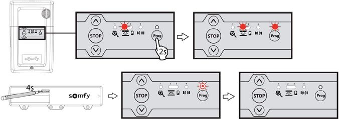
Door Service & Safety Check
                       style, security, innovation...

    AlluGuard recommends that the door is regularily serviced by a competent person. We recommend
    the following forms the minimum basis of a full door service.

    Visual Checks
    Check exterior of curtain for debris/salt/dirt signs of rubbing or scuffing - clean as required.
    Advisory notes:
    Check operation on all handsets and wall station buttons/ change batteries after 18 months or second service.
    Advisory notes:
    Check bottom safety edge operations and condition of bottom rubber seal / change battery after 18 months or on second service.
    Advisory notes:
    Remove back box and check straps and rings haven’t moved or become loose and fur still in place.
    Advisory notes:
    Check bottom and top limits of operator haven’t crept forward reset if necessary.
    Advisory notes:
    Check top laths haven’t moved left /right or lost end caps - adjust and re fix as required.
    Advisory notes:
    Check safety brake is free of debris all fixings are tight, bottom bolt of safety brake should be set at 15lbs only.
    Advisory notes:
    Check end plate fixings - must have at least one good solid fixing each side check rollers and guide fur are in good order and clean.
    Advisory notes:
    Clean any debris from hood replace and check manual winder operation check eye is in line with motor and not causing stress.
    Advisory notes:
    Change batteries in safety edge if wireless after 18 months or on second service.
    Advisory notes:
    Change batteries in handsets after 18 months or on second service.
    Advisory notes:
    Inspect bulb and change if required. Ensure no debris in bulb holder.
    Advisory notes:
    Operate door and check for rubbing / scuffing and ensure guides are clean.
    Advisory notes:
    Check all Fixing points on the guides.
    Advisory notes:
    Check top and bottom magnets are in place and operating correctly.
    Advisory notes:
    Check power supply cable is secured and in good order. Check control box is not on a damp wall, fit spacers if required.
    Advisory notes:
    Test safety edge for function.
    Advisory notes:

8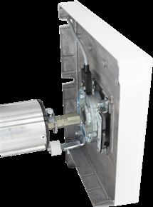
Service & Maintenance Record
Date   Work Carried Out   Work Performed By   Print   Signed   Company Name

                                                                              9
Instructions for competent engineer
or DHF trained garage door installer.
Installation Manual
Important: Please read these instructions carefully
prior to commencing the installation of the door.
The AlluGuard door has been designed to provide DANGER
years of trouble free use. The door will perform
Disconnect electric power to the control unit before
efficiently only if it is installed and operated correctly.
making repairs or removing covers.
Read these important safety Install the Remote Control Box (or any additional
rules first: push buttons) in a location where the garage door
This equipment must be installed and used in is visible, but out of the reach of children. Do not
accordance with these instructions. Failure to follow allow children to operate push button(s) or remote
these instructions could result in damage to the control(s). Serious personal injury from a closing
integrity of the safety circuits. garage door may result from misuse of the operator.
Two persons are required to install this product CAUTION
to ensure safe handling procedures. Activate unit only when the door is in full view, free
CAUTION of obstructions and operator is properly adjusted. No
one should enter or leave the garage while the door
Do not wear rings, watches or loose clothing while is in motion. Do not allow children to play near
installing or servicing the unit and ensure correct PPE the door.
is worn.
To avoid serious personal injury from entanglement,
remove any loose objects from the equipment prior
to operating door.
DANGER
Installation and wiring must be in accordance with
your local building and electrical regulations.
Any electrical work must be carried out by a suitably
qualified person, if in doubt consult a qualified
Note to
Installer
electrician.
Use only the mains lead supplied with the Remote
Control Unit as failure to do so will invalidate the
warranty. Please ensure this installation and
user manual remains with the end
Connect the mains lead to an adjacent 13amp 3 pin
switched socket.
user as it contains important safety
and warranty information.
The plug must be fitted with a 13 amp fuse.
Note: For optimum electrical safety this unit
should be connected to circuit protected by a
R.C.D. (max 30 mA trip rating).
style, security, innovation...
This unit should not be installed in a damp or wet
space or on a damp or single skinned wall without
sufficiient spacers.
1011
Component Check
     Unpack and check that all components are present.
     ✓ C urtain Assembly                                     ✓ Control System Comprised of:
         (inc. set of Pre-fitted Locking Straps)                      •   Control unit (The light bulb is not
                                                                          covered under manufacturer’s warranty)
     ✓ Axle Assembly                                                 •   Mains lead
         (pre-fitted with Motor, Locking Rings and
         Dummy End)                                                   •   Pair magnets
                                                                      •   2No Remote hand transmitters
     ✓ Pair of Guide Rails                                           •   Safety edge transmitter (The battery
         (pre-fitted with brush strips)                                   is not covered under manufacturer’s
                                                                          warranty)
     ✓ Box Assembly Comprised of:
             •    1 pair of end plates (pre-fitted with               •   Fittings Pack
                    guide rollers & safety break)
             •    1 motor override eye and manual
                    winding handle
             •    1 fittings pack

     1. Pre-Installation Check
     Important Note: In case of power failure a manual override system is fitted as standard
     but this can only be operated from inside the garage.
     If the garage has no service entrance door then an exterior release kit must be fitted to
     allow manual operation of the garage door from outside.
     1. BEFORE REMOVING THE OLD DOOR check that               3.4. The door package and its contents should be
     the door size and colour correspond with that which      checked for obvious damage before removal of the
     was ordered.                                             wrapping.

     2. Structural condition of opening                       IF THERE IS ANY DAMAGE YOUR SUPPLIER
                                                              SHOULD BE CONTACTED IMMEDIATELY.
     Ensure the area around the opening is strong
     enough to support the door                               4. Ensure there is a suitable 13amp 3 pin switched
                                                              socket adjacent to where the Remote Control Box is
     The surface where the door is to be fitted must be       to be fitted.
     flush and reasonably smooth.
                                                              5. Ensure all tools and door components are
     Small irregularities in the brickwork will be            gathered together inside the garage prior to starting
     acceptable. The lintel must not protrude backwards       the installation.
     or forwards from the brick piers. Should the lintel
     protrude backwards or forwards from the brick piers      Tools Required:
     this will require special instructions, please consult
     your AlluGuard Approved Installer.                       •   2 Stepladders           •   7.0 drill bit
                                                              •   Spirit/laser level      •   11.0 drill bit
     3. Fitting Notes
                                                              •   Steel tape              •   Hacksaw
     3.1. It is recommended that 2 people are available
     for fitting all door sizes.                              •   Power drill             •   Suitable wall plugs
                                                                                              (not supplied)
                                                              •   10mm A/F spanner
     3.2. The door must be fitted square and level,
     irrespective of the shape of the opening; on no          •   Slot screwdriver        •   Small electrical
     account should any compensation be made to suit                                          screwdriver
     an irregular opening.                                    •   Pozidrive               •   3mm A/F Allen key
                                                                  screwdriver
     3.3. Ensure all necessary tools are to hand before       •   4mm A/F Allen key       •   Suitable fixings
     starting.                                                                                (not supplied)
                                                              •   3.8 drill bit
12
2. Check Headroom
The headroom is the clear vertical height required between the top of the guide rails and any obstruction
above the shutter as shown in Fig 1 and Fig 2.
This space is required to house the door roll headroom of 205mm / 300mm is required. (AG55 requires 205mm
& AG77 requires 300mm).
Limited Head room
If insufficient headroom is available the door can still be fitted (see your survey sheet) but the shorter guide
rails will give a corresponding reduction in door opening height as shown in Fig 3. The curtain will require 1
lath to be removed for every 75mm of reduction in the guide height.
Note: Ensure that the headroom above the guides is clear of any obstructions (especially small protrusions or
nail heads) which could cause damage to the door roll during installation/operation.
Fig 1: Headroom within aperture Fig 2: Headroom behind aperture Fig 3: Limited headroom
3. Preparing the Guide Rails
3.1 For Fitting Within The Aperture
3.1.1 Check Guide Rail Length
Check that guide rails have been supplied to the correct length as per your survey sheet / order. The correct
length is aperture height less 205mm or 300mm as shown in Fig 1.
3.1.2 Drill Fixing Holes
Drill holes through 7mm diameter and counter drill 11mm diameter as shown in Fig 4.
A minimum three holes per rail are required, positioned as shown in Fig 5.
NB. Position holes for best fixing to brickwork.
3.2 For Fitting Behind The Aperture
3.2.1 Check Guide Rail Length
Check that guide rails have been supplied to the correct length as per your survey sheet/order.
A. Where headroom of 205mm / 300mm or more is available guide rail length equals aperture height as
shown in Fig 6.
B. Where only limited headroom is available guide rail length equals total available height less 205mm /
300mm as shown in Fig 7.
Fig 4 Fig 5 Fig 6 133.2.2 Drill Fixing Holes
Drill holes through 7mm diameter & counter drill 11mm diameter as shown as shown in Fig 8.
A minimum three holes per rail are required as shown as shown in Fig 9.
NB position holes for best fixing to brickwork.
Fig 7 Fig 8 Fig 9
4. Assemble the Frame
4.1 L/H or R/H Motor (Factory Fitted as Standard)
The motor and control unit can be mounted on either the L/H side or R/H side. (Please specify at time of order).
All AlluGuard doors are fitted with a safety brake as standard excluding AG55 Doors shown in Fig 10.
• If you want to change the hand of the motor this should be carried out by a suitably trained engineer.
• If you do move the Motor & Safety Brake ensure that these are installed correctly otherwise the unit will not
activate under normal running conditions.
• It is important that the head plates are securely fixed – 2 fixings per head plate.
4.2 End Plates and Safety Brake Device* (Safety brake factory fitted as Standard)
Lay the Head assembly on protective packing, parallel with and just inside the
garage opening.
Ensure the motor is situated at the correct end for your installation and that the
motor limit adjusters are at the top/bottom as shown in Fig 11.
Fix the motor plate to the end plate by using four M6 x 25 countersunk screws
and Nyloc nuts provided.
Fig 11
Safety Brake
Fig 10 Shaft
Dummy End
Fig 10a
Safety Collar
Fig 10b Fig 10c
Safety Collar Safety Collar tight against
14 the dummy endThe safety brake is prefitted to the end plate as standard (Fig 10). Loosen the safety coller on the dummy end
shaft, extend the shaft fully into the safety brake (Fig 10a). Slide the safety collar tight up to the dummy end
and tighten.(Fig 10b & 10c).
4.3 Fit Guide Rails
Select R/H guide rail and slide fully onto the bottom square tube spigot projecting from the R/H end plate,
please ensure that the End Plate is flush with the face side of the guide rail.
Repeat for the L/H guide rail as shown in Fig 12.
L/H R/H
Fig 12
5. Install the Frame
You will have drilled your guide rails, as shown in Fig 4 or Fig 8, for fitting either:-
a) Within the aperture b) Behind the aperture
Please proceed accordingly. (SAFETY NOTE: 2 people required)
5.1 Fitting Within Aperture
For installation within the aperture we strongly recommend the use of a cover box as this covers and protects
the door curtain roll.
5.2 If either half box or full box options are specified these will be supplied factory fitted to the end plates.
5.3 Lift the frame assembly into position and align with the front of
the aperture.
Ensure the guide rails are VERTICAL (in both directions) and parallel
to each other, at the same height and the correct distance apart.
NB: Some width adjustment is available on the sliding shaft end of
the axle.
The correct distance is shown in Fig13. – AG77 Door
Fig 13
Ensure the axle assembly is horizontal by using a spirit level.
5.1.3 Once the frame is correctly positioned, mark and drill for fixings (fixings not supplied).
5.1.4 When the guide rails are securely fixed, double check that they are vertical, parallel and correct distance
apart and that the axle assembly is level.
5.4 Fixing The Head Plates
Fix the head-plates into position ensuring that the head-plates are level and that the locating pegs are fully
located into the guide section. Fix securing screws through back of head-plate and attach securely to the wall.
Where a back box is fitted it may be necessary to fix the back box to the opening header to stop any marking
of the curtain during door operation. If additional fixings are required in the back box, use countersunk screws,
ensuring that the screw heads do not protrude, as curtain damage could occur.
Always ensure that the back box is adequately fixed to eliminate any rubbing of the curtain on the
back box during the door operation and fixing are evenly spaced to ensure no bowing of the box. 155.5 Fitting Behind Aperture / Fitting to the Front of the Aperture (External Fit)
Lift the frame assembly into position and align centrally with the aperture. Ensure the guide rails are vertical (in
both directions) and are parallel to each other, at the same height and the correct distance apart.
NOTE: Some width adjustment is available on the sliding shaft end of the axle. The correct distance apart is
shown in Fig 13.
When fitting to the front of the aperture (external fit/reverse roll), once installation is complete, the
box must be siliconed at the interface with the aperture and along all edges and joints to prevent
water ingress. Failure to seal will invalidate the warranty. The bottom slat transmitter must be fitted
to the inside face of the bottom slat (concave face). Fitting to the external face of the slat will lead to
failure and invalidate the warranty.
Ensure axle assembly is horizontal by using a spirit level.
5.6 Once the frame is correctly positioned, mark and drill for fixings (fixings not supplied).
5.7 When guide rails are securely fixed, double check for vertical, parallel and correct spacing and that the axle
is level.
NOTE: Once the frame is fully fitted and checked, use the plastic plugs supplied to cover the fixing holes in the
guide rails to give a ‘fully finished’ effect.
5.8 Fixing the Head Plates
Fix the head-plates into position ensuring that the head-plates are level and that the locating pegs are fully
located into the guide section. Fix securing screws through back of head-plate and attach securely to the wall.
Where a back box is fitted it may be necessary to fix the back box to the opening header to stop any marking
of the curtain during door operation. If additional fixings are required in the back box, use countersunk screws,
ensuring that the screw heads do not protrude, as curtain damage could occur.
Always ensure that the back box is adequately fixed to eliminate any rubbing of the curtain on the
back box during the door operation.
6. Installing the Curtain Assembly
6.1 Carefully unwrap and remove the outer bubble wrap protection and place over shaft to stop damage to
inside of curtain during installation.
6.2 Carefully position the curtain assembly in the door
Fig 14
aperture, below the axle as shown in Fig 14, slit the
packaging to gain access to the curtain but leave some
packaging to protect the curtain.
6.3 SAFETY NOTE: A minimum two people are required
for this procedure to ensure safe handling.
6.4 It is essential to place sections of bubble wrap over the
axle to prevent marking the curtain as it is installed.
6.5 Using minimum 2 people carefully lift the curtain
assembly up level with the axle. Practice has shown that it
is best to place one hand on the axle, keeping that arm straight, and support the curtain roll on that shoulder
as shown in Fig 15.
6.6 Feed the bottom lath over the top of the axle and down between the guide rails, as shown in Fig 16 taking
care not to scuff the curtain assembly, proceed until half of the curtain has been fed over the axle, carefully
unroll the remaining curtain until this is balanced over the shaft, once this is done carefully feed the curtain
into the guide until the curtain is reaches the floor.
NOTE: Do not let the curtain ‘free fall’ over the axle as this will result in damage to the Curtain and/or the
Safety Edge Transmitter.
16Fig 15 Fig 16
7. Attach the Curtain
7.1 Fit the Motor Override
Attach the ‘Motor Override Eye’ fitting to the motor as shown in Fig 17 using
3mm screw.
7.2 Position the Axle
Use the motor override to rotate the axle shaft.
Rotate the axle until the locking joint attachment holes are positioned as
shown in Fig 18.
7.3 Locking Ring
There is a locking ring positioned on the shaft for each locking strap; the
number of locking rings will vary according to curtain width and AG55 - 2
rings & AG77- 1 ring per strap.
Position the outermost ring/s to the shaft approx. 150mm in from each end
and equally space the other/s as shown in Fig 19. Fig 17
Slide each locking strap along the top lath and engage the fastening pin into
the appropriate hole in the respective clamped locking ring/s, (AG55 Doors).
Slide the loose locking ring to engage the other end of the fastening pin and secure the loose locking ring to
the shaft using the self tapping screw on AG55 doors.
Repeat this for each locking strap, as shown in Fig 19.
7.4 Locking Ring (AG77)
The locking rings are pre-attached on the barrel, to connect the locking straps, line up with the locking ring
hole and insert pin. Space the lock rings with 800mm between them.
Fig 18 Fig 19 17The support straps should be positioned centrally or equidistant. Support straps are available fom the
sales office, should the box require support.
8. Connect the Electrics
8.1 Preparing the AlluGuard Roller Garage Doors for Remote Control for
Installation
• Remove the integrated light cover from the top of the Somfy Rollixo Control
Unit.
• Unscrew and remove the receiver cover from the unit by loosening the one
screw at the base of the unit.
8.2 Fixing the Somfy Rollixo Remote Control to the Wall
• Make sure that the unit is mounted onto internal brickwork and is firmly fixed.
• The unit must be installed with the courtesy light at the top. Hold the unit
against the wall at a height of at least 1.6 meters and mark where the screw
fixings should be as shown in Fig 20.
• Take the unit away and drill the holes. Fix unit to the wall.
THIS MUST BE FITTED INSIDE THE GARAGE AS IT IS NOT IP RATED
8.3 Plug power lead into 13A socket but DO NOT SWITCH ON at this stage.
8.4 Connect the safety brake cable to terminals 5 and 6. Alternatively use a
test lead.
9. Setting the Curtains Open
and Close Position
Fig 20
Somfy Motor Set-Up
Motor and fall protection wiring.
The receiver must not be connected to the mains power supply during connection to the motor.
9.1 Motor Wiring
9.1.1 Connect the motor to the receiver.
Note: the motor’s direction of rotation shall then be checked and reversed if necessary.
9.1.2 Lock the motor cable with the cable clamp provided.
The motor cable must be placed in the receiver’s 230v insulation area.
Fall protection wiring.
If no fall protection is connected, it is essential to create the bridge between terminals 5 and 6
of the receiver (with the shunt provided).
189.2 Connecting the Receiver to the Mains Power Supply
9.2.1 Fully unfold the receiver aerial so that it is pointing downwards.
9.2.2 Screw the bulb supplied into the receiver. (Before connecting to mains power supply)
9.2.3 Replace and screw in the receiver cover.
9.2.4 Refit the integrated light cover.
9.2.5 Connect the receiver to the mains power supply.
All the indicator lights come on and then go out.
If indicator light 1 comes on permanently, fall protection is not connected or incorrectly connected to the
receiver.
If indicator light 2 comes on permanently, the safety edge has not been detected by the receiver (radio safety
edge transmitter not yet memorised or the wired safety edge is still not connected).
9.3 Checking the Direction of Rotation of the Motor and Adjustment of the Motor End Limits
9.3.1 Press simultaneously on the ^ and v buttons until the motors up and down movement occurs to enter
motor adjustment mode.
• Indicator light 1 flashes slowly.
9.3.2 Press button ^ or v to check the motor’s direction of rotation.
If the motor’s direction of rotation is correct, move on to step [3] of the motor end limit setting procedure.
If the direction of rotation is incorrect, press button (stop) until the motors up and down movement occurs,
check the motor’s direction of rotation again and move on to step [3] of the motor end limit
setting procedure.
9.3.3 If the motor end limits are already set, move on to step [8] to exit motor adjustment mode.
• If the motor end limits are not set, check that the motor is released: the two push-buttons should
be pressed.
Note: The motor end limits can also be set with a setting tool (ref. 9015971).
In this case, set the motor end limits with the cable then move on to step [8] to exit motor adjustment mode.
9.3.4 Press ^ button to position the garage door in the upper position.
• Adjust the upper position with buttons ^ and v.
9.3.5 Press the motor’s upper end limit push-button. Somfy Motor
9.3.6 Press v button to position the
garage door in the lower position.
• Adjust the low position with
buttons ^ and v.
9.3.7 Press the motor’s low end limit
push-button.
9.3.8 Press simultaneously on the ^
and v buttons or press the (prog)
button until the motor’s up and down
movement occurs to enter motor
adjustment mode.
• Indicator light 1 goes out.
19Progressive Motor Limit Set-up
9.4 Limit Switch Adjustment (see Fig 22)
The limits are set at the factory to 8 revolutions of the shaft, A 4mm
‘Allen Key’ limit adjuster is used to adjust them further.
Allow the motor to run downwards without the curtain attached
to enable the shaft to determine bottom limit position, without
curtain attached to shaft.
9.5 Adjustment ‘Up’
Run the motor up with the curtain attached, if the motor stops
short of fully open, turn the adjusting screw in the + direction (this
is the adjuster indicated by the rotation of the barrel. This will allow Fig 21
the motor to run on in the up direction.
Stop the motor before it gets to the fully open position and wind
the adjuster in the – direction until it stops before the fully open
position. Keep the open button pressed and at the same time
slowly turn the adjuster in the + direction until the door stops
at the fully open position. If the motor runs too high, turn the
adjustment screw towards the - direction until the motor stops in
the correct position.
9.6 Adjustment ‘Down’
Run the motor down, if the motor stops short of the closed
position, turn the adjustment screw towards the + direction
keeping the control pressed in the down direction until the correct
position is reached. Fig 22
If the motor runs too far turn the adjustment screw towards the –
direction.
Set open position as shown in Fig 21.
9.7 Checking the Limit Positions
Run the motor in both directions until the limit switches cut out the motor travel.
Carry out any fine adjustments. One turn of the adjustment screw corresponds to approximately 70° turn
of the roller tube.
In order that the locking joints
operate effectively, the position
of the shaft in the closed position
needs to be finely adjusted.
Do not adjust past this position as
this will impose excessive loads on
the mechanism.
This motor is fitted with a thermal
trip; this stops the motor from
overheating.
Be aware that excessive running of
the door may cause the thermal trip
to operate, if this happens; please
wait 20 minutes before trying to
operate the door again.
2010. Position the Magnets on the Door Guide
& Programming the Safety Edge Transmitter
IMPORTANT: Do not introduce the bottom magnet to the guide for the first time with the curtian in the
closed position, this will compromise the set up process. Using the test lead or control box buttons, send
the door down to the bottom limit position. Mark the guide in pencil at the point in line with the arrow on the
bottom slat transmitter. Open the door half way. Fit the bottom magnet over the mark using the sticky pad as
shown in Fig 24.
Send the door up to the fully open postion. Measure 70mm down from the bottom edge of the bottom slat
transmitter and mark the guide in pencil. Send the door down to half way and then fix the top magnet using
the sticky pad. Fig 23.
Fig 23 Fig 24
Programme the bottom slat transmitter into the control box Fig 25.
Programming the XSE Transmitter in to the Rollixo Receiver
Press the ‘Prog’ button on the Rollixo RTS front panel until the LED above the Prog button lights up RED.
Press the ‘PROG’ button on the safety edge transmitter for approximately 4 seconds until the ‘Prog’ LED on
the Rollixo RTS controller flashes and then goes out.
Fig 25
Now, using the control box, send the door up to its open position. Then, using the down arrow, send the
door, in one movement, all the way to the close position. The bottom slat transmitter should switch off
about 10 seconds after closing.
Failure to follow this procedure can cause the alarm to sound a short while after installation.
Once the safety edge transmitter is in full working order then fix the magnets in place using the self
tapping screws provided
Please refer to the Somfy instructions on commissioning a safe edge if required. If you require support, call
Somfy Technical Assistance on: 0113 391 3014
21Additional Problem Solving
10.1 Door Tight Or Jams In Operation
• Check for good entry of curtain laths into guide rails.
• Check that bottom lath is correctly engaged into track when fully open, as shown in Fig 21.
• Check for correct clearance of curtain in guide rails. NB: laths should have a sideways ‘end float’ of
approx 6mm.
• Adjust guide rails if necessary to achieve free movement.
10.2 Recalibration of the bottom slat transmitter required
• Press and hold the mode button = LED flash red
• Release the mode button = LED solid red
• Allow the left LED to flash green
• Allow the right LED flash green
• Immediately press the safety edge twice in quick succession to activate it. The LED should flash red
then go solid green if the transmitter has been reset.
Rollixo RTS XSE Kit Contents
The Rollixo XSE Kit is supplied with the following:
No. Description
1. 1 x Rollixo RTS Controller
2. 1 x Rollixo RTS Installation Guide
3. 1 x Rollixo RTS End User Guide
4. 1 x Quick Fit Mains Supply Cable
5. 1 x Wiring Accessory Bag – Contains:
1 x Motor Supply Cable Clamp & 2 x Cable
Clamp Screws
1 x Wire Link (to bridge the safety brake
terminals)
1 x Alarm Sounder Screw
6. 2 x Keygo 4 RTS Radio Keyfobs
7. 1 x Courtesy Light Bulb
8. 1 x XSE Safety Edge Transmitter
9. 1 x XSE Safety Edge Transmitter
Installation Guide
10. 1 x Bag of XSE Safety Edge Transmitter
Screws (x4)
11. 2 x Guide Magnets
22EMR (Exterior Release Kit)
Installation Instructions
23Do not attempt to work on the door unless
System Diagnostics you are a trained engineer
The Rollixo Remote Control System provides a full fault finding diagnostic programme,
this is all dependent on there being power to the unit.
24
Somfy Technical Assistance - t: 0113 391 3014DECLARATION OF INCORPORATION
style, security, innovation...
We, AlluGuard Limited
Of Rotherham Road, Parkgate Rotherham S62 6FP
Declare that: Power Operated Roller Garage Door
Models: AlluGuard 77 and AlluGuard 55
Manufactured by: AlluGuard Limited
Are in conformity with the essential Health and Safety requirements of the Machinery Directive 2006/42/EC.
And conform with the Low Voltage Directive 2006/95/EC, and the Electromagnetic Compatibility Directive
2004/108/EC.
A technical file of documentation has been compiled in accordance with Annex VII (Part 7 of Schedule 2), part
B. AlluGuard undertakes to transmit, in response to a reasoned request by the national authorities, relevant
information on this partly completed machinery. Transmission shall be via electronic or paper copies, and
shall be without prejudice to the intellectual property rights of the manufacturer of the partly completed
machinery.
The product to which this Declaration of Incorporation relates must not be put into service until the relevant
machinery into which it is to be incorporated has been declared in conformity with the provisions of the
Machinery Directive.
KSpence
Kevin Spence
Managing Director
25EC DECLARATION OF CONFORMITY - CUSTOMER COPY
THE SUPPLY OF MACHINERY (SAFETY) REGULATIONS 1992
Model: Serial Number:
Size (W x H):
Installed By:
The above power operated door (door, operator, safety devices, etc.), has been assembled, installed,
connected and tested in accordance with the manufacturer’s instructions, at the following site address and
is in conformity with the provisions of the Machinery Directive (89/392/EEC as amended by 91/368/EEC and
93/336/EEC), the Low Voltage Directive (73/23/EEC) and EMC Directive (89/336/EEC).
The Transposed Harmonised Standards used in the design of the above door are as follows: EN 13241-1:2003, &
12453:2001.
Site Address:
Declaration (made by installation engineer):
Signature: Print name:
Date: Tel:
Declaration and instructions received by:
Signature: Print name:
Date: Tel:
26EC DECLARATION OF CONFORMITY - INSTALLER COPY
THE SUPPLY OF MACHINERY (SAFETY) REGULATIONS 1992
Model: Serial Number:
Size (W x H):
Installed By:
The above power operated door (door, operator, safety devices, etc.), has been assembled, installed,
connected and tested in accordance with the manufacturer’s instructions, at the following site address and
is in conformity with the provisions of the Machinery Directive (89/392/EEC as amended by 91/368/EEC and
93/336/EEC), the Low Voltage Directive (73/23/EEC) and EMC Directive (89/336/EEC).
The Transposed Harmonised Standards used in the design of the above door are as follows: EN 13241-1:2003, &
12453:2001.
Site Address:
Declaration (made by installation engineer):
Signature: Print name:
Date: Tel:
Declaration and instructions received by:
Signature: Print name:
Date: Tel:
27AlluGuard Technical Assistance - t: 01709 529 723 / 07795 103 133
Somfy Technical Assistance - t: 0113 391 3014
style, security, innovation...
AlluGuard Limited
Rotherham Road, Parkgate, Rotherham S62 6FP
t: 01709 529 723
f: 01709 524 577
e: info@alluguard.co.uk
w: www.alluguard.co.uk
AlluGuard reserve the right to alter specifications to design and manufacture without notification.
All specifications are correct at time of publication, errors and omissions excepted. May 2021You can also read