A White Paper on Resilience Engineering for ATM - Cooperative Network Design
←
→
Page content transcription
If your browser does not render page correctly, please read the page content below

A White Paper
                        on Resilience Engineering for ATM

Cooperative Network Design

                                                    EUROCONTROL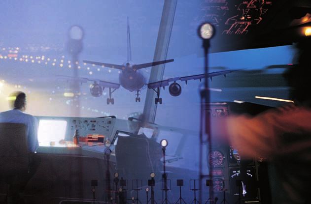
Tempora mutantur, nos et mutamur in illis
(“Times change, and we change with them”)
introduction

In January 2007, a project was launched by EUROCONTROL with the aim of understanding the new area of Resilience
Engineering and its relevance to Air Traffic Management (ATM). Resilience Engineering is developing important tools
and methods for both system developers and people responsible for the maintenance and management of system
safety, in a number of industries.

This White Paper provides an overview of the work carried out and seeks to answer the following questions:

n   What is Resilience Engineering?

n   Why do we need it in ATM?

n   What is the usefulness of performance variability?

n   What does Resilience Engineering look like in practice?

n   How does Resilience Engineering fit with other safety methods?

n   How mature is Resilience Engineering and what is the added value for ATM?

The added value of an Resilience Engineering approach is that it provides a way to address the issues of emergent
accidents and the often disproportionate consequences that are an outcome of ever more complex technologies
and ever more integrated organisations. Resilience methods are likely to be important tools in the management and
assurance of ATM safety in the future.

RESILIENCE ENGINEERING for ATM

What is Resilience Engineering?

                                                       Since humans are indispensable in all situations involving
                                                       change, Resilience Engineering naturally has strong links
     Resilience is the intrinsic ability of a system   with Human Factors and Safety Management. It is based
     to adjust its functioning prior to, during, or    on the following premises:
     following changes and disturbances, so that
     it can sustain required operations under both     1. Performance conditions are always underspecified.
     expected and unexpected conditions.                  Individuals and organisations must therefore adjust
                                                          what they do to match current demands and re-
                                                          sources. Because resources and time are finite, such
                                                          adjustments will inevitably be approximate.

                                                       2. Some adverse events can be attributed to a break-
                                                          down or malfunctioning of components and nor-
                                                          mal system functions, but others cannot. The latter
                                                          can best be understood as the result of unexpected
                                                          combinations of performance variability.
     Performance variability:
     The ways in which individual and collective       3. Safety management cannot be based exclusively on
     performances are adjusted to match current           hindsight, nor rely on error tabulation and the cal-
     demands and resources, in order to ensure            culation of failure probabilities. Safety management
     that things go right.                                must be proactive as well as reactive.

                                                       4. Safety cannot be isolated from the core (business)
                                                          process, nor vice versa. Safety is the prerequisite for
                                                          productivity, and productivity is the prerequisite
                                                          for safety. Safety must therefore be achieved by im-
                                                          provements rather than by constraints.

                                                       Adopting this view creates a need for an approach that
                                                       can represent the variability of normal system perfor-
                                                       mance, and for methods that can use this to provide
                                                       more comprehensive explanations of accidents as well
                                                       as identify potential risks.

2
From Safety Management to Resilience
Engineering
Risk governance and safety management have tradi-                The focus of Resilience Engineering is on the whole set
tionally, and with good reason, been concerned with              of outcomes, i.e., things that go right as well as things
what can go wrong and therefore lead to unwanted out-            that go wrong – with the possible exceptions of the areas
comes. The set of possible outcomes can schematically            of serendipity and good luck, where we are mostly in the
be shown as in Figure 1, where the x-axis describes pre-         hands of fate.
dictability, ranging from very low to very high, and the
y-axis describes the value of the outcome, ranging from          The aim of Resilience Engineering is not only to prevent
negative to positive.                                            things from going wrong, but also to ensure that things
                                                                 go right, i.e., to facilitate normal outcomes. Simply put,
The established approaches to risk and safety mainly             the more likely it is that something goes right, the less
focus on the things that go wrong, more specifically             likely it is that it goes wrong. And there is clearly an
those areas in figure 1 named disasters, accidents, and          added value in trying to facilitate normal outcomes and
incidents – with occasional forays into near misses. The         in discarding the traditional separation between safety
mishaps region describes unwanted outcomes that in               and productivity.
practice have been eliminated. But there has traditional-
ly been little or no focus on things that go right, despite
the fact that these happen far more often than things
that go wrong. If, for instance, the probability of failure is
10-4, then there will be 9,999 normal outcomes for every
failure!.

OUTCOME
Positive

              Serendipity

                                                          Normal outcomes
                                                          (things that go right)

                          Good luck
Neutral

                                                       Incidents           Near misses

                                 Accidents
Negative

              Disasters                                                                 Mishaps
                                                                                                          PREDICTABILITY
           Very low                                                                           Very high

                                         Figure 1: The set of possible outcomes

RESILIENCE ENGINEERING for ATM                                                                                                3
Why do we need Resilience Engineering?
A simple answer to this question is given by the types dents even further, it also means that those that do slip
of accidents that can occur in complex yet ‘well-de- through these ‘nets’ will be complex and multi-faceted.
fended’ systems, of which Air Traffic Management (ATM) Such accidents will be due more to coincidences among
is a good example. While accidents such as Überlingen the variability of functions and human performance in
(2002) with hindsight can be explained by failure modes different parts of the system, than to manifest failures
emerging from the weak interaction of multiple factors, and incorrect human actions.
few would have considered this situation credible ahead
of time. Traditional thinking makes it difficult to describe Accident analysis and risk assessment methods have
and understand how multiple factors can come to- usually been developed in response to problems fol-
gether at a single point of time and in a position of lowing major technological developments or to cope
airspace to produce something as disastrous as a mid- with ‘new’ types of accidents. Figure 2 shows the distri-
air collision. bution of some well-known methods used to address
technical, human factors, and organisational issues,
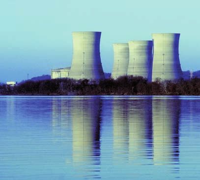
Today, most ANSPs have safety nets, Safety Manage- respectively. It is noteworthy that human factors meth-
ment Systems (SMS), safety assessment and assurance ods came onto the scene after the accident at Three
processes, and many are also improving their safety Miles Island in 1979, and that organisational methods
culture. These efforts add layers of safety to already safe were developed following the Chernobyl and Chal-
systems. While this will reduce the likelihood of acci- lenger accidents in 1986.
RCA, ATHEANA
HEAT TRIPOD
MTO
Swiss cheese
HPES
STEP FRAM
HERA
HCR
AcciMap STAMP
HAZOP THERP AEB
CSNI MERMOS
Root cause Domino FMEA Fault tree
FMECA TRACEr
MORT CREAM
1900 1910 1920 1930 1940 1950 1960 1970 1980 1990 2000 2010
Technical Human Factors Organisational Systemic
Figure 2: Accident Analysis and Risk Assessment Methods
4Methods must clearly be powerful enough to address the problems found in real-life applications. Established ways of thinking about accidents, such as the Swiss Resonance: Cheese analogy of holes in safety barriers that ‘line up’, A principle that explains how dispropor- will therefore at some time be unable to prevent, pre- tionate large consequences can arise from dict, and explain new types of accidents. The variability seemingly small variations in performance of normal performance may for instance combine to and conditions. produce effects that go beyond what the Swiss Cheese analogy was intended to describe, even if the holes are allowed to grow or shrink dynamically and the blocks of cheese allowed to move around. In order to address these more complex phenomena, Resilience Engineer- ing uses the principle of resonance to represent how the variability of normal performance can combine dynamically in ways that may lead to disproportionate (non-linear) effects. Safety assessment methods have historically developed from technical methods, via hu- man factors methods, to organisational methods. While many current methods combine the technical, human, or organisational levels, resonance must be treated at the system level. Figure 3: ‘Swiss Cheese’ Model RESILIENCE ENGINEERING for ATM 5
The usefulness of performance
          variability
          The first premise of Resilience Engineering makes clear
          that performance variability is inevitable but also useful.                       Organisation
                                                                                           (management)
          Procedures and instructions are always incomplete,
          except for extremely simple situations. Following proce-                                       Downstream

          dures and instructions to the letter will therefore both
          be inefficient and unsafe. To compensate for this incom-
          pleteness, individuals and organisations habitually ad-         Design                                  Maintenance

          just their performance to match the current demands,
          resources, and constraints. The ability to do so is at the
          heart of successful performance. But since information,              Upstream

          resources, and time are finite, the adjustments will in-                         Technology
          evitably be approximate. Performance variability is thus
          unavoidable, but should be recognised as a source of                     Figure 4: Safety Focus anno 1984
          success as well as of failure.

                                                                        Socio-technical systems have since the 1980s become
                                                                        steadily more complex due to rampant technological
                                                                        and societal developments. The idea of a socio-techni-
                                                                        cal system is that the conditions for successful organisa-
                                                                        tional performance – and conversely also for unsuccess-
                                                                        ful performance – depends on the interaction between
                                                                        social and technical factors. The scope of safety assess-
                                                                        ment must therefore be extended in several directions.
                                                                        A ‘vertical’ extension is needed to cover the entire sys-
                                                                        tem, from technology to organisation. One ‘horizontal’
                                                                        extension is needed to increase the scope to include
                                                                        both design and maintenance. A second ‘horizontal’ ex-
                                                                        tension is needed to include both upstream and down-
                                                                        stream processes. Altogether, the situation today there-
                                                                        fore looks more as shown in Figure 5.

                Organisation                                                                Organisation
               (management)                                                                (management)

                              Downstream                                                                 Downstream

          This has, however, not always been so. The concern for
Design                                 Maintenance                        Design                                  Maintenance
          how human factors could affect safety began with the
          accident at the Three Mile Island nuclear power plant
          in 1979. At that time, the focus was naturally on control
    Upstream                                                                   Upstream
          room operations (the ‘sharp end’), and methods were
          therefore  developed to support that. The situation in
                Technology                                                                 Technology
          the 1980s with regard to the focus of safety is depicted
          in Figure 4.                                                             Figure 5: Safety Focus anno 2009

6
Upsteam-downstream means integration into the plex than the systems of yesteryear. Because there are
company’s business. In aviation, gate-to-gate would be many more details to consider; because some modes of
an example, i.e. you can no longer consider previously operation may be incompletely known; because of tight
separate functions as separate. There are dependencies couplings among functions; and because systems may
to what went before (upstream) and what comes after change faster than they can be described, the net result
(downstream). In general production it is ‘just in time’ is that many systems, ATM included, are underspecified
(JIT) in order to remove the need for inventories (raw or intractable. For these systems it is clearly not possible
materials, spare parts etc). to prescribe tasks and actions in every detail. This means
that performance must be variable or flexible rather than
As a result of these developments, safety methods must rigid. In fact, the less completely the system is described,
today address systems that are larger and more com- the more performance variability is needed.
Tractable system Intractable system
Description are simple with few Description are elaborate with
Number of details
details many details
Principles of functioning are Principles of functioning are
Comprehensibility
known partly unknown
System does not change while System changes before description
Stability
being described is completed
Relation to other systems Independence Interdependence
Metaphor Clockwork Teamwork
Table 1: Differences between tractable and intractable systems
It is useful to make a distinction between tractable and
intractable systems. Tractable systems can be completely
Tight
Financial
Power NPPs systems described or specified, while intractable systems cannot.
Dams grids
Aircraft
The differences between the two types of systems are
Military
Railways operations summarised in Table 1.
Emergency Integrated
management operations
Most established safety methods have been devel-
Marine ATM oped on the assumption that systems are tractable.
transport
Coupling
As this assumption is no longer universally valid, there
is a need to develop methods to deal with intractable
Mining Space
Healthcare
missions systems. Resilience Engineering is one answer to this
Manufacturing problem.
Universities Public
services
Post Figure 6 shows the result of characterising different
offices
Assembly socio-technical systems on the dimensions of ‘Coupling’
lines
Loose
and ‘Manageability’. Existing methods are not well
suited for systems in the upper right quadrant (intrac-
Tractable Manageability Intractable
table and tightly coupled), which makes this a primary
Figure 6: System Characteristics focus for Resilience Engineering.
RESILIENCE ENGINEERING for ATM 7The reasons for performance
variability
To predict how resonance may lead to accidents, we The challenge for resilience engineering is to represent
must be able to describe and model the characteristic the variability of a system, such as ATM, in a way that
variability of the system. A main source of performance makes it possible to identify what may affect perfor-
variability is the underspecification of work, as described mance either adversely or positively. This must overcome
in the previous section. In addition to the underspecifi- two obstacles:
cation, human performance can vary for several other
reasons: 1. Because ATM is a complex and intractable system,
its functions, their interactions, and potential vari-
ances, can only be specified approximately.
Physiological and/or fundamental
psychological factors (e.g., affecting 2. In a time of traffic growth, planned changes to ATM’s
perception and vigilance). fundamental infrastructure and technical systems
must be reconciled with strong but varying financial
pressures and demands.
Higher level psychological factors such The ATM system environment feels the effect of the
as ingenuity, creativity, and adaptability. resulting instability and increasing variability as
ANSPs try to ride out the changes whilst remaining
safe and profitable. This requires them to be flexible,
to rely on human ingenuity and skill, and to make
use of performance variability rather than to con-
Organisational factors, as in meeting strain it.
performance demands, stretching re-
sources, substituting goals, etc.
Social factors, as in meeting expectations
of oneself or of colleagues, complying
with informal work standards, etc.
Contextual factors, for instance if the
workplace is too hot, too noisy, too hu-
mid, etc.
Other factors such as the unpredict-
ability of the domain, e.g., weather
conditions, number of flights, pilot
variability, technical problems, etc.
8How is it done?
Resilience Engineering provides the conceptual basis for FRAM is a developing method. The following is an illus-
a new perspective on safety. The leading prototype cur- tration of what a FRAM analysis might look like for an
rently is the Functional Resonance Assessment Method overflight scenario:
(FRAM). This method is based on four principles:
A FRAM analysis consists of five steps:
n The equivalence of success and failures. Failures
do not stand for a breakdown or malfunctioning of 1. Define the purpose of the analysis. FRAM can be
normal system functions, but rather represent the used for safety assessment (looking at future events)
adaptations necessary to cope with the underspeci- as well as for accident investigation (looking at past
fication found in complex real-world systems. events).
n The principle of approximate adjustments. To 2. Identify and describe the relevant system functions.
get anything done people must adjust their perfor- A function, in FRAM terms, constitutes an activity
mance to the current conditions. Because resources or task which has important or necessary conse-
and time are finite, such adjustments will inevitably quences for the state or properties of another ac-
be approximate. tivity. Each function is characterised by six aspects:
Input, Output, Preconditions, Resources, Time and
n The principle of emergence. Both failures and nor- Control, as depicted in Figure 7.
mal performance are emergent phenomena: neither
can be attributed to or explained simply by refer- 3. Assess and evaluate the potential variability of
ring to the (mal)functions of specific components or each function. FRAM uses a distinction between
parts. foreground and background factors, which may all
affect performance variability. Foreground factors
n The principle of functional resonance. FRAM re- are directly associated with the functions being
places the traditional cause-effect relation with reso- modelled and may vary significantly during a sce-
nance. This explains how the variability of a number nario, while background factors refer to common
of functions every now and then may resonate, i.e., conditions that may vary more slowly. Both sets of
reinforce each other, leading to excessive variability factors should be calibrated as far as possible using
in one or more downstream functions. The conse- information extracted from accident databases.
quences may spread through the system by means of
tight couplings rather than easily identifiable cause- 4. Identify where functional resonance may emerge.
effect links. This step finds the possible ways in which the vari-
ability from one function can spread through the
Time T C Control system. In case of functional resonance, the com-
binations of this variability may lead to situations
where the system loses its capability to safely man-
age variability.
Function/
Input I O Output
Process
5. The fifth and last step is the development of
effective countermeasures. These usually aim
at dampening performance variability in order to
Precondition P R Resource
maintain the system in a safe state, but can also be
used to sustain or amplify functional resonance that
Figure 7: The six aspects of a FRAM function leads to desired or improved outcomes.
A/C 1: radio
contact established
T C T C
RESILIENCE ENGINEERING for ATM 9
Issue
I clearance O I Coordination OAn example of what this looks like, applied to an over-
flight scenario, is in the following. The analysis of system
functions (Step 2) produced the following list:
n Provide ATC clearance to pilot
n Monitoring
n Planning
n Strip marking
n Coordination
n Update flight data processing system
n Provide meteorological data to controller
n Provide flight and radar data toControl
Time T
controller
C
n Controller-pilot communication
n Sector-to-sector communication
Function/
Input I O Output
Process
By characteristing each function using the six aspects
described in Step 2 above
Precondition P (cf., Figure
R Resource7), the following
instantiation of the model was produced.
A/C 1: radio
contact established
T C T C
Issue
I clearance O I Coordination O T C
to pilot Team
T C coordination Pilot -
P R P R ATCO
I O
communi-
Provide cation
I O Flight position A/C 1
MET data monitored
Clearance A/C 1:
P R
Climb to FL100
T C A/C 1: radio
MET data
P R contact established
Clearance plan A/C 1: T C
Climb to FL100
I Monitoring O
T C
Strip
Flight position A/C 1 I O
Flight & radar data marking
P R monitored
I Planning O
T C P R
Provide P R A/C 1 strip marked:
FDPS updated
flight & Climb to FL100
I O
radar
data
T C Request from
T C
next sector:
Team
P R Climb to FL100
FDPS updated coordination
Sector to
Update I sector O
I O comm.
FDPS
P R
P R
Figure 8: Instantiation of the FRAM model for the overflight scenario
10How does Resilience Engineering fit
with other safety methods?
Resilience Engineering is a developing approach, one that provides an additional perspective on safety assessment
and management and offers potential resilience assessment techniques, such as FRAM, to complement existing
tools. Adopting a Resilience Engineering view does not require that existing practices are discarded wholesale. But it
does mean that they are looked at in a different way, which in turn may change how they are applied, as well as the
way in which their results are interpreted.
ty
tional Safe
Organisa
Technical Safety
Human F
actors
Resilie
nce E
engin
eerin
g
Figure 9: Widening perspectives on safety
How mature is Resilience Engineering?
At present, the use of Resilience Engineering in ATM is at the feasibility stage of development. The research team
working on the project will complete a first main case study for ATM in 2009, which will show how this approach
works in detail and what it can deliver. The example will be a study of a Minimum Altitude Safety Warning (MSAW)
system. Following that, further test cases should be conducted to develop and mature the approach to make it an
additional tool for safety cases. While this inevitably will require some time, the goal is to have the methodology fit
for use prior to SESAR’s implementation phase in 2013.
In other domains, such as general aviation, offshore production, and healthcare, Resilience Engineering has been
used longer and has provided a substantial body of knowledge and experience. This has been documented in a
number of books and marked by several international symposia and workshops, as well as commercial applications,
e.g. maintenance of heavy machinery, risk modeling of helicopter safety, and patient safety.
RESILIENCE ENGINEERING for ATM 11What is the added value of Resilience
Engineering?
This key question can obviously best be answered after n Performance variability enables individuals and or-
Resilience Engineering has been seen ‘in action’ in ATM. ganisations to adjust what they do to match current
Since it addresses a difficult problem, more than one resources and demands. Performance variability is
case study may be needed to demonstrate its full po- the reason why things go right, and sometimes also
tential. However, there is an obvious value in having a the reason why things go wrong.
technique which can explain and predict the complex
accident scenarios that defeat existing barriers and n Resilience Engineering complements existing safety
defences, and that also tries to facilitate normal out- methods. It offers a different perspective, but is not
comes. intended to be a wholesale replacement.
In summary, the questions posed at the beginning of n Resilience Engineering has been actively developed
this brochure can be answered as follows: since 2004, and has been successfully applied to acci-
dent investigation and risk assurance in several indus-
n Resilience Engineering goes beyond classical safety trial domains, eg. maintenance of heavy machinery,
issues by recognising that safety and production are risk modeling of helicopter safety, and patient safety.
intrinsically linked. The aim of Resilience Engineer-
ing is to develop models and methods to improve This has been documented in a number of books and
an organisation’s ability to succeed under varying marked by several international symposia and work-
conditions, thereby enhancing both safety and daily shops, as well as commercial applications, e.g. risk
operations. modeling of helicopter safety, patient safety, and main-
tenance of heavy machinery. In the latter cases one
n Resilience Engineering is needed because many technique was to implement a new alarm process to
current systems are underspecified, hence exceed identify signs that things were getting worse, as a basis
the premises of existing safety analysis methods. for timely remedial interventions.
Conclusion
This White Paper has presented the main concepts and practical principles of Resilience Engineering, a developing
field which will be important for ATM safety in the future. ATM is among the socio-technical systems that have developed
so rapidly that established safety assessment approaches are increasingly challenged to address all the issues and
identify all the risks. In complex socio-technical systems, things may go wrong in the absence of manifest failures
and malfunctions, and outcomes may often be disproportionately large. To safeguard against such developments,
it is necessary to have tools and methods that can deal with the underspecification and tight couplings of complex,
highly interactive systems such as ATM. Resilience Engineering offers a conceptual and methodological basis for
achieving that goal – it is ‘one to watch.’ The research and development efforts will continue and further results will
be documented and disseminated as a way of demonstrating the added value of the approach. Special emphasis
will be put on case studies and guidance on how a smooth integration with conventional safety assurance schemes
can be accomplished.
Some additional reading is suggested below.
12Further Reading:
http://www.resilience-engineering.org/
Hollnagel, E. (2004).
Barriers and accident prevention. Chapter 5 & 6. Aldershot, UK: Ashgate publishers.
Hollnagel, E., Woods, D. D. & Leveson, N. (2006).
Resilience engineering: Concepts and precepts. Aldershot, UK: Ashgate publishers.
Hollnagel, E. (2009).
The ETTO principle: Efficiency-thoroughness trade-off. Why things that go right sometimes go wrong.
Aldershot, UK: Ashgate publishers.
Woltjer, R. & Hollnagel, E. (2008).
Modeling and evaluation of air traffic management automation using the functional resonance accident model (FRAM).
8th International Symposium of the Australian Aviation Psychology Association, Sydney, Australia.
GLOSSARY
Intractable: A system which cannot be described in every detail and where the functioning there-
fore is not completely understood. Intractable systems are only partly predictable.
Performance variability: The ways in which individual and collective performances are adjusted to match cur-
rent demands and resources, in order to ensure that things go right.
Resilience: The ability of a system to succeed under varying and adverse conditions.
Resonance: A principle that explains how disproportionate large consequences can arise from
seemingly small variations in performance and conditions.
Safety culture: That assembly of characteristics and attitudes in organisations and individuals which
establishes that, as an overriding priority, safety issues receive the attention warranted
by their significance.
Serendipity: The making of happy and unexpected discoveries by accident or when looking for
something else; such as discovery.
RESILIENCE ENGINEERING for ATM 13For further information contact:
Project Team
Jörg Leonhardt, holds a Master Degree of Luigi Macchi is a PhD student in the Industrial
Human Factors and Aviation Safety from Lund Safety Chair of the Mines-ParisTech University
University, Sweden. He is Head of Human Fac- (France). He holds a Psychology degree from
tors in the Safety Management Department of the Università degli Studi di Torino (Italy). His
the German Air Navigation Service Provider, PhD adopts the Resilience Engineering per-
DFS. spective and aims to develop a safety assess-
He is Project Leader the EURCONTROL’s FA- ment methodology accounting for the human
RANDOLE Project, “A resilient approach to contribution to Air Traffic Management safety.
evaluate the human contribution to system
Safety” and member of the EUROCONTROL luigi.macchi@mines-paristech.fr
HERA User Group.
Joerg.Leonhardt@dfs.de EUROCONTROL Point of Contact
Erik Hollnagel is Professor and Industrial Dr Barry Kirwan leads Safety Research and De-
Safety Chair at MINES ParisTech (France) and velopment in EUROCONTROL. He has degrees
Visiting Professor at the Norwegian University in Psychology, Human Factors and Human Re-
of Science and Technology (NTNU) in Trond- liability Assessment. He has worked in the nu-
heim (Norway). He has for many years worked clear, chemical, petrochemical, marine and air
at universities, research centres, and industries traffic sectors of industry, and lectured at the
in several countries and with problems from University of Birmingham in Human Factors.
several domains, including nuclear power He was formerly Head of Human Reliability at
generation, aerospace and aviation, software BNFL in the UK nuclear industry, and Head of
engineering, healthcare, and land-based traf- Human Factors at NATS (UK). For the past nine
fic. He has published widely and is the author/ years he has been working for EUROCONTROL,
editor of 17 books, including three books on managing a team of safety researchers and
Resilience Engineering. The latest title from safety culture specialists at the EUROCONTROL
Ashgate is “The ETTO Principle: Why things Experimental Centre in Bretigny, near Paris. He
that go right, sometimes go wrong.” has published four books and around 200 ar-
ticles. He is also a visiting Professor of Human
erik.hollnagel@mines-paristech.fr Reliability & Safety at Nottingham University
in the UK.
barry.kirwan@eurocontrol.int
EUROCONTROL
© European Organisation for the Safety of Air Navigation (EUROCONTROL). September 2009
This document is published by EUROCONTROL for information purposes. It may be copied in
whole or in part, provided that EUROCONTROL is mentioned as the source and it is not used for
commercial purposes (i.e. for financial gain). The information in this document may not be modified
without prior written permission from EUROCONTROL.
www.eurocontrol.intYou can also read