AUGER USER GUIDE SUPPORTING OUR CUSTOMERS TO CREATE SAFE WORKING ENVIRONMENTS - MGF
←
→
Page content transcription
If your browser does not render page correctly, please read the page content below
AUGER USER GUIDE
        SUPPORTING OUR CUSTOMERS TO
   CREATE SAFE WORKING ENVIRONMENTS

                           mgf.co.uk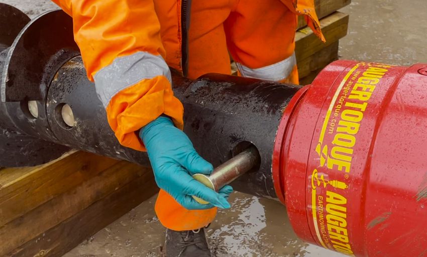
SUPPORTING OUR CUSTOMERS
    TO CREATE SAFE WORKING
    ENVIRONMENTS
    With 40 years of experience, MGF is a privately-owned company whose primary focus is the
    provision of fully engineered excavation support solutions to the civil engineering, construction,
    rail and utilities sectors. We combine technical expertise and operational performance to ensure
    the highest levels of customer service. With a focus on developing and promoting industry best
    practice in excavation safety we aim to assist our customers in creating safe working environments
    for their employees.

    CUSTOMER SERVICE AND SUPPORT
    The hire and sale of our products is fully supported by our team of qualified engineers,
    experienced Technical Sales Representatives, hire desk and operational staff. Our hire centres
    provide the focal point for service delivery where our hire desk team will be pleased to receive
    your enquiry.

    DELIVERY CAPABILITIES
    Our dedicated fleet of vehicles offer a flexible solution to quickly meet our customers delivery
    needs throughout the UK. We partner with several global shipping companies to ensure we can
    quickly deliver our products on a global scale.

2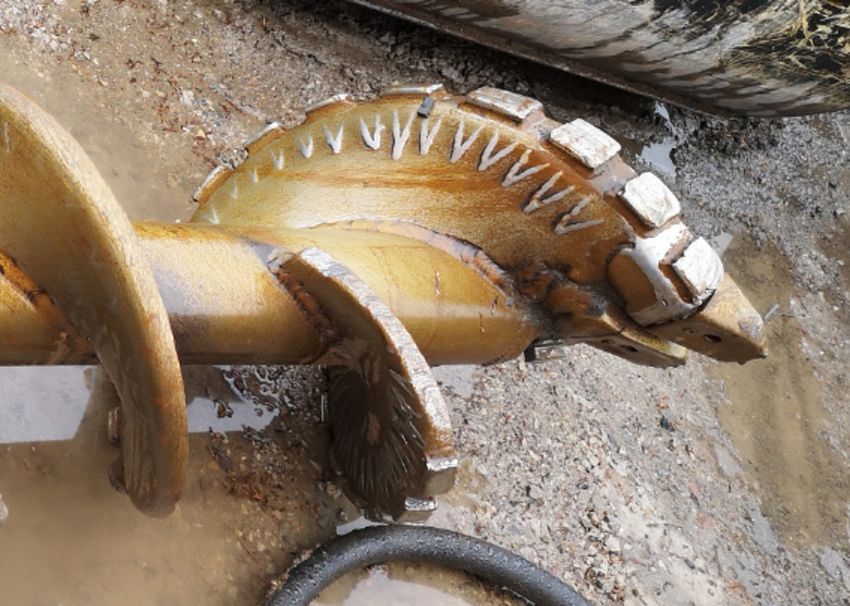
USER GUIDE
                                                                                          AUGER
CONTENTS
SECTION 1: INTRODUCTION TO AUGERS 			                                          4
1.1    WHAT ARE PILING AUGERS OR PRE-AUGERS?
1.2    WHAT CAN MGF PILING AUGERS BE USED FOR?
1.3    WHAT ARE THE BENEFITS OF MGF PRE-AUGERS?
1.4    SPECIFICATION
1.5    PARTS DESCRIPTION / IDENTIFICATION

SECTION 2: COMPONENT IDENTIFICATION
- WEIGHTS & DIMENSIONS					                                                    8
2.1    CRADLE & DRILL MOTOR
2.2    QUICK HITCH HEADS
2.3    DRILLS
2.4    TELESCOPIC EXTENSION
2.5    WEIGHTS AND DIMENSIONS

SECTION 3: RISK ASSESSMENT CHECKLIST		                                     12
3.1    RISK ASSESSMENT CHECKLIST
3.2    DO’S / DON’T’S

SECTION 4: AUGER OPERATION			                                              14
4.1    AS DELIVERED
4.2    LOCKING THE MOTOR TO THE CRADLE
4.3    EQUIPMENT ARRANGEMENT FOR CONNECTION
4.4    CONNECTING THE CRADLE / MOTOR QUICK HITCH TO AN EXCAVATOR QUICK HITCH
4.5    CONNECTING THE CRADLE / MOTOR TO THE DRILL
4.6    PREPARATION
4.7    DRILLING PROCEDURE
4.8    AUGER ALIGNMENT
4.9    DRILLING WITH EXTENSIONS – TELESCOPIC & FIXED
4.10   TRANSPORTATION

SECTION 5: STEPS TO ATTEMPT RELEASE
OF HYDRAULIC PRESSURE IN ‘PECKER CIRCUIT’
OF AN EXCAVATOR						                                                      32
SECTION 6: MAINTENANCE				                                                 35
6.1    DAILY CHECKS
6.2    WEEKLY CHECKS

SECTION 7: TROUBLESHOOTING				                                             38
7.1    FAULT – CAUSE - ACTION

SECTION 8: REFERENCES				                                                  39
SECTION 9: TORQUE / SPEED GRAPHS FOR 35000MAX                              40
USER GUIDE SECTION 1
AUGER

                            INTRODUCTION TO AUGERS
                            1.1 WHAT ARE PILING AUGERS OR PRE-AUGERS?
                            A Piling Auger is a type of drill that incorporates a helical screw blade, sometimes called
                            a ‘flight’ which in construction is used to drill or loosen earth in preparation for driving
                            sheet piles.

                            1.2 WHAT CAN MGF PILING AUGERS BE USED FOR?
                            Pre-augering is mainly used in difficult stiff ground conditions where it is necessary to use
                            the pre-drive sheet installation method to turn cohesive soil into less dense material. This
                            reduced density allows installation or removal of piling sheets via an Excavator Mounted
                            Vibrator (EMV) Hammer in conditions which without the auger would not have been possible.

                            1.3 WHAT ARE THE BENEFITS OF MGF PRE-AUGERS?
                            A Piling Auger is fitted to an excavator in the same way as an EMV and using the pre-
                            augering method means a vibratory hammer can be used in place of an impact hammer.
                            Using a piling auger as a method of preparing the soil is beneficial for several reasons:
                            • Alternative option if EMV sheet driving refuses due to stiff ground conditions.
                            • Quieter than using impact hammer.
                            • Reduces damage to piling sheet drive edges and EMV damage due to refusal.
                            • Reduced outlay vs – hiring larger impact vibro hammers and cranes. Highly specialised
                              install teams required for more complex methods.
                            • To suit excavator sizes 13t – 45t.
                            • Quickly interchangeable with MGF EMV units, via quick release hydraulic connections –
                              same flows and pressure so no setup change. Quick tool change on excavator maximises
                              productivity onsite.
                            • Quick hitch mounted – Ø65, 80, 90 & 100 diameter pin options to suit a broad range of
                              quick hitch types and models.
                            • MGF designed cradle – allows superior control of drill movement, from horizontal to
                              vertical orientation, connecting, and whilst tracking the excavator on site. The cradle
                              also functions as a carry frame and carries its own spares / tools self-contained upon it.
                              It features lift points compatible with MGF standard duty 4-leg chains, as well as forklift
                              points.
                            • 3.2m length custom built drills – configured with ‘Rock’ specification teeth, hard wear
                              pads, shallow pitch flights for the full length of drill. Heavy-duty tube construction. Fully
                              flighted Ø400mm diameter – or Ø600mm diameter drills available.
                            • Available with a telescopic extension, to add additional 0.75m or 1.5m length with ease
                              and quick turnaround time. Because the telescopic extension is inside the drill tube
                              at start of operation, full depth drilling beyond boom reach can be achieved without
                              disconnecting drills. Simply stop augering, remove pin, extend, or retract, re-lock,
                              continue augering with minimal time disruption and greater safety.

 4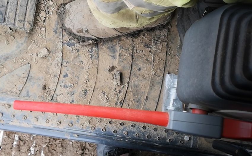
USER GUIDE SECTION 1
                                                                                                                   AUGER
1.4 SPECIFICATION
         AUGER MODEL 35000MAX
 Torque Range            20,510 – 35,323 Nm
                           180 - 310 bar
 Oil Pressure Range
                           2610-4500 psi

 Oil Flow Range          80 - 225 l/minute*
 Speed Range                11 - 31 rpm
 Unit Height                  1411mm
 Unit Diameter                406mm
 Motor Unit Weight             470kg
 Output Shaft Std          110mm square

* Flow rates quoted are continuous. Intermittent flow rates up to 225lpm allowed.

1.5 PARTS DESCRIPTION / IDENTIFICATION

                            4 lift points for use with MGF
                             standard duty 4 leg chains
     Quick hitch
    bolted head
   Ø65mm, 80mm,
   90mm,100mm
                                                   Oil level check
                                                    cover panel

                                                                               Drill motor

                                                                                             Motor seal

                            Forklift
                             point
                                                Motor to cradle
   Cradle – acts as                             locking pin and                  1t lift point
   transport frame                                 linch pin                 (for drill handling)

                               4 spare – Ø30 drill pins
                                  and stowage point

                                                                                                                           5
USER GUIDE SECTION 1
AUGER
                                                                     Swivel bar               Ø60 pivot pin, c/w grease
                                                                                              nipple. Typically 2 pins –
                                                                                                 see weekly checks
                                       Stowage points for
                                        bow shackle and
                                          fabric sling

                                 Quick hitch head                                                          Unit ident no
                                   plate bolting
                               – see weekly checks

                            Drive socket 110SQ                          Tube / shaft        Flight               Tooth

                                                                                                                    Pilot
                                                     Ident no

                                                                                         Ø30 drill pin

                                            Note: Linch pin fits only in          Note: Fixed pin head fits in
                                          scalloped / milled recess only.          circular recess side only.

 6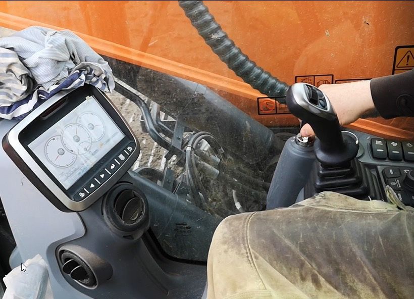
USER GUIDE SECTION 1
                                                                                                  AUGER
                                                             Ø30 drill pin –
                                                         ‘telescopic adjust pin’

           Ø30 drill pin – ‘telescopic lock pin’
             *Do not remove in normal use

Ø30 drill pin –
‘telescopic to
  motor pin’

                                            Telescopic
                                            extension

       Ident no

                                                                                                          7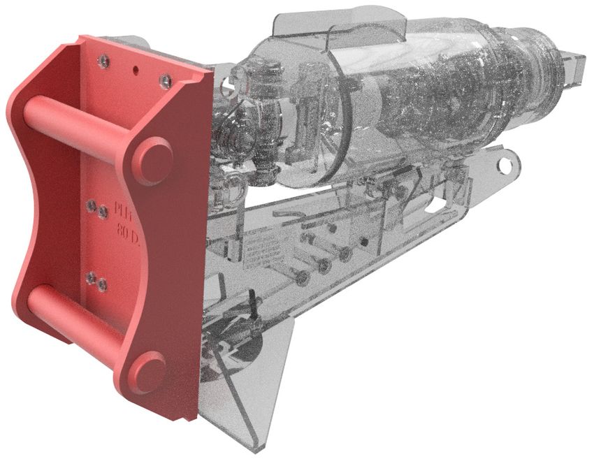
USER GUIDE SECTION 2
AUGER

                            COMPONENT IDENTIFICATION
                            - WEIGHTS & DIMENSIONS
                            2.1 CRADLE & DRILL MOTOR

                                 PRODUCT ID            WEIGHT
                                                            (kg)
                                     2.950                  835

                            2.2 QUICK HITCH HEADS

                            (Customer choice – fitted
                            pre hire) – {secured via 17 -
                            M20x90 hex bolt iso4017 grd
                            8.8, washer and nyloc nut.}

                               PRODUCT ID              DESCRIPTION            WEIGHT
                                                                               (kg)
                                  PLH-65           Ø65 Pin Quick Hitch Head    135
                                  PLH-80           Ø80 Pin Quick Hitch Head    160
                                  PLH-90           Ø90 Pin Quick Hitch Head    198
                                  PLH-100         Ø100 Pin Quick Hitch Head    214

 8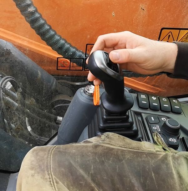
USER GUIDE SECTION 2
                                                                                                               AUGER
2.3 DRILLS

(Customer choice of Ø400 – or – Ø600)
Note: 13t - 20t excavators should have Ø400 drill only with or without telescopic extension.
20t - 45t can have either Ø400 or Ø600 drill with or without telescopic extension.

     PRODUCT ID                               DESCRIPTION                            WEIGHT
                                                                                       (kg)
          2.951                       Auger Drill - Ø400, 3200mm long                  320
          2.952                       Auger Drill - Ø600, 3200mm long                  450

2.4 TELESCOPIC EXTENSION

(Customer choice – fitted pre hire) secured using ‘Ø30 drill locking pin and linch pin’
- 3 positions, extension increments = 750mm, so 0mm – 750mm – 1500mm extension.

     PRODUCT ID                               DESCRIPTION                            WEIGHT
                                                                                       (kg)
          2.953                  Auger Drill Telescopic Extension - 1500mm             180

Note: A ‘red’ highlighted section is present on the telescopic extension to warn the operator
they are in the vicinity of the last hole when changing set length.

                                                                                                                       9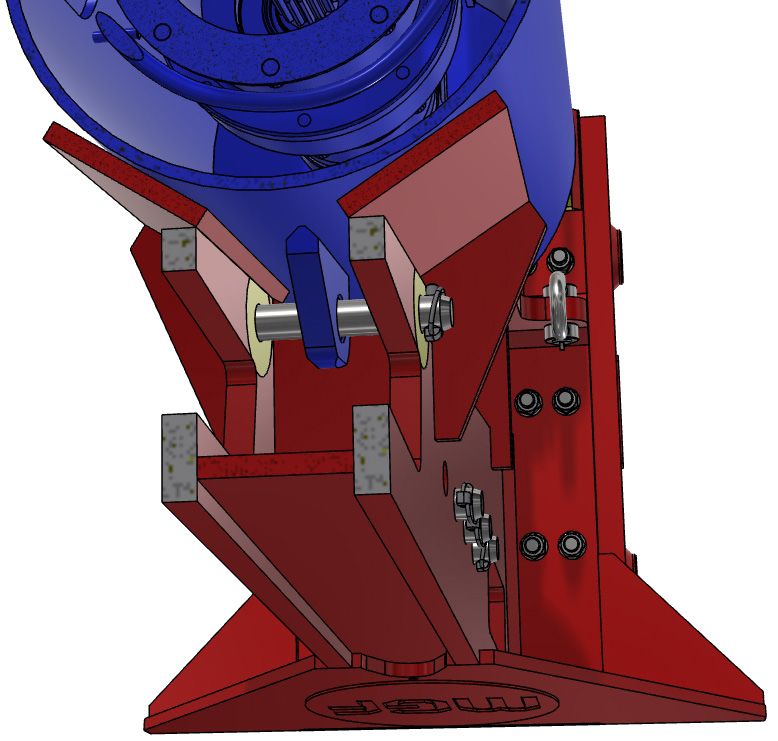
USER GUIDE SECTION 2
AUGER
                             2.5 WEIGHTS AND DIMENSIONS
                             WEIGHTS AND DIMENSIONS - NO TELESCOPIC STRUT

                                                     4967 - MIN EXCAVATOR REACH DIM (NOT INC QH)

                             165          1387

                                                                                                                     Ø400

                                                                                                                     Ø600
                                                                                                                      or
                                                                          3415 - MAX DRILL DEPTH - (NO TELESCOPIC)

                                      Drill direct to motor
                                        (No telescopic)

                               Weights (not inc QH Head):
                               • Cradle & Motor & Ø400 Drill = 1155kg
                               • Cradle & Motor & Ø600 Drill = 1285kg

 10
USER GUIDE SECTION 2
AUGER
WEIGHTS AND DIMENSIONS - IF TELESCOPIC STRUT FITTED
5487 - MIN EXCAVATOR REACH DIM (NOT INC QH)
165 1387 (520)
Ø400
Ø600
or
3935 - MAX DRILL DEPTH - PIN POS 00
Telescopic strut fitted
750 - PIN POS 01
4685 - MAX DRILL DEPTH - PIN POS 01
1500 - PIN 02
5435 - MAX DRILL DEPTH - PIN POS 02
Weights (not inc QH Head):
• Cradle & Motor & Ø400 Drill & Telescopic Strut = 1335kg
• Cradle & Motor & Ø600 Drill & Telescopic Strut = 1465kg
11USER GUIDE SECTION 3
AUGER
RISK ASSESSMENT CHECKLIST
3.1 RISK ASSESSMENT CHECKLIST
• Consult manufacturer’s manual before use.
• Ensure a pre-hire checklist has been completed.
• Ensure that a site / task specific Risk Assessment / Method Statement (RAMS) has been
prepared prior to use.
• Ensure that lifting operations have been appropriately planned prior to use.
• Ensure that all associated equipment is of sound condition, rated appropriately and is
tested in accordance with legislative requirements.
CONSIDER THE FOLLOWING WHEN PREPARING YOUR RAMS
The following list is not exhaustive:
• Have all relevant persons been consulted prior to operations commencing
• The selection of competent fitters and operatives
• Falling drills / piles / equipment / ancillaries
• High pressure fluid injection
• Overturning of plant / equipment
• Proximity of operatives
• Third parties and plant in proximity of operations
• Trapping / impact and other mechanical hazards
• Heat from Auger when in use and post use
• Proximity of overhead cables and underground services
• Ground conditions
• Environmental impacts
• Ensure that Temporary Works Coordinators (TWC) and Temporary Works Supervisors
(TWS) have been consulted prior to operations commencing.
• If works are permanent, ensure a suitably qualified engineer has been consulted prior to
operations commencing.
• Ensure competent operatives are appointed to fit Augers / EMVs to excavators prior to
operations commencing.
• Ensure competent operatives and supervisors are appointed to operate and assist in the
operation of Augers / EMVs prior to operations commencing.
• Ensure control measures are in place for the protection of operatives, third parties, plant
and structures in the proximity of operations prior to them commencing.
• Augers / EMVs should only be operated on stable ground.
• Ensure any overhead cable hazards and associated risks are identified and controlled.
• Ensure that regular checks are carried out to ensure that hazards are controlled and the
equipment is in good working order.
• Ground vibrations may lead to substantial nuisance or hazard to the adjoining areas.
• Improper use of the Auger can lead to dangerous situations.
12USER GUIDE SECTION 3
AUGER
3.2 DO’S / DON’TS
ONLY OPERATE THE AUGER IF YOU ARE SUITABLY QUALIFIED
AND COMPETENT TO DO SO.
SET UP AND ENFORCE AN ‘EXCLUSION ZONE’.
COMPLETE ALL THE REQUIRED WEEKLY, DAILY AND PRE-USE
CHECKS – REPORT ANY DEFECTS.
ENSURE THERE IS ALWAYS VISUAL CONTACT BETWEEN THE
OPERATOR AND THE SLINGER / SIGNALLER (OR BANKSMAN).
MONITOR THE AUGERING OPERATION CONSTANTLY – INTERRUPT
THE PROCESS IMMEDIATELY IF THERE ARE OPERATIONAL
ISSUES OR ANY DANGEROUS (OR SUSPECTED DANGEROUS)
SITUATION OCCURS.
FOLLOW THE AGREED (AND BRIEFED) SAFE SYSTEM OF WORK
/ RAMS.
DO NOT OPERATE THE AUGER IF ANYONE IS IN THE EXCLUSION
ZONE.
DO NOT ENTER THE ‘EXCLUSION ZONE’ IF THE AUGER IS BEING
OPERATED.
DO NOT USE THE AUGER IF IT IS FAULTY IN ANY WAY.
DO NOT INSERT FINGERS INTO PIN BORES.
DO NOT TOUCH THE AUGER DURING THE OPERATING PROCESS
(EVEN IF THE EXCAVATOR IS SWITCHED OFF) AS IT CAN
BECOME HOT.
DO NOT USE A DRILL IF WEAR STRIPS ARE WORN AWAY –
CONTACT MGF FOR REPLACEMENT OR REPAIR OF THE DRILL.
DO NOT DRILL BEYOND STATED MAX DEPTHS – THE MOTOR SEAL
MUST NOT CONTACT GROUND OR BE DRIVEN BELOW GROUND.
IT MUST ALWAYS BE KEPT VISIBLE AND ABOVE GROUND LEVEL.
13USER GUIDE SECTION 4
AUGER
AUGER OPERATION
4.1 AS DELIVERED
The Auger motor will be delivered to site fitted on its cradle, which also acts as a
transport stillage.
The cradle will be fitted and supplied with the hirer’s choice of quick hitch head size.
The hirer’s choice of drill size will be delivered (with or without telescopic strut extension),
not fitted to the motor. If telescopic strut is specified this will be supplied in the fully
closed position.
The Auger motor will be locked to the cradle, using one of the ‘Ø30 drill locking pin and
linch pin’ – placed in the locking position hole on the cradle and secured with linch pin.
4.2 LOCKING THE MOTOR TO THE CRADLE
(FOR CROWDING, HANDLING OR TRANSPORT)
The locking pin – when fitted through the highlighted hole, passes through a lug on the
motor body. This prevents the motor from being able to articulate from its pivot on the
cradle.
THE LOCKING PIN MUST BE FITTED ANYTIME THE AUGER
IS BEING HANDLED / TRANSPORTED WHEN NOT ON THE
EXCAVATOR.
THE LOCKING PIN MUST BE FITTED BEFORE CROWDING
THE AUGER DURING LOCKING OR UNLOCKING OF THE
QUICK HITCH ON THE EXCAVATOR. SERIOUS INJURY OR
DAMAGE COULD OCCUR IF THIS STEP IS NOT UNDERTAKEN.
Note: Only the highlighted ‘locking hole’ serves this function. The other holes are for holding
spare pins only and do not provide a lock function.
14USER GUIDE SECTION 4
AUGER
Section cut through nose of
cradle (motor and lug coloured
blue for clarity) – illustrating
how locking pin must pass
through all three bores and be
secured with linch pin before it
is considered secure.
A Ø30 drill pin is used to
lock the connection – do
not use any other item or
material.
This can be checked /
verified by looking through
the forklift pocket hole.
Be cautious of finger traps
or hand / limb traps.
15USER GUIDE SECTION 4
AUGER
4.3 EQUIPMENT ARRANGEMENT FOR CONNECTION
IT IS ADVISED THAT THE AUGER SHOULD BE FITTED BY AN MGF
SERVICE ENGINEER MAKING THE NECESSARY HOSE CONNECTIONS AND
CHECKING FOR FULL FUNCTIONALITY. THE AUGER SHOULD ONLY BE
OPERATED BY SUITABLY TRAINED PERSONNEL.
Arrange equipment
Using the fabric as shown, so that
sling and shackles centre lines fan back
(stowed on the carry to the pivot axis of
frame) orientate the the excavator.
drill so the teeth are
between the tracks.
Lift and elevate the
connection end either
using timbers, a
scoop of earth, or a
trestle. (550mm min
– floor to underside of
drive socket.)
Drills can be lifted and handled using the centre of gravity balanced holes in the flights.
A 4.75t bow shackle (2 bow shackles and a 2t fabric sling provided and fitted to the
MGF cradle).
The drills have two holes.
The hole nearest the drilling tip, is balanced for if ‘no telescopic strut extension’ fitted.
The hole nearest to the connection socket, is balanced for if ‘telescopic strut extension’
fitted.
Drills can be moved or handled, either via connecting to the quick hitch bow shackle point
or using the bow shackle connection point at the nose of the MGF cradle (note 1t rating).
16USER GUIDE SECTION 4
AUGER
4.4 CONNECTING THE CRADLE / MOTOR QUICK HITCH
TO AN EXCAVATOR QUICK HITCH
Fully extend the bucket ram – which is often
referred to as ‘crowding the quick hitch’.
Disengage the locks (following quick hitch
manufacturer instructions), and visually
confirm these are open by inspection.
*Ensure the cradle / motor lock pin is fitted.
Hook onto the top pin, rotate the quick hitch so that both pins of the
quick hitch head are within the quick hitch clamp points.
17USER GUIDE SECTION 4
AUGER
Fully extend the bucket ram – which is often referred to as ‘crowding the quick hitch’.
Lock the quick hitch (following quick hitch manufacturer instructions), and visually
confirm these are open by inspection.
Once locked return the Auger cradle to floor position.
18USER GUIDE SECTION 4
AUGER
Inspect locks
Connect the quick release hydraulic fittings to the relevant quick release fitted
on the excavator boom. The drain line is the smaller hose. The inlet hose will be
marked by the MGF fitter by putting red insulation tape around both hose and
quick release fitting. The outlet hose will have no colour marking.
(Note: This is the same set up for as used for MGF EMV hammer hire – so tools are
quickly interchangeable).
Note: A Pressure Reducing Valve maybe fitted to the inlet side of the boom quick release
fitting, if machine setup / flows dictate this is required.
If pressure is locked in the hydraulic lines preventing quick release fitting insertion or
removal, see sub section 5 in this guide.
Check operation of drill in both directions by using the pecker control lever.
Remove motor / cradle locking pin – stowing the pin in the cradle stowage point (secure
with linch pin).
19USER GUIDE SECTION 4
AUGER
4.5 CONNECTING THE CRADLE / MOTOR TO THE DRILL
(Ensure locking pin removed)
Position the excavator arm so the drill axis is aligned to the motor axis,
and so that the drive head is in front of the drill drive socket.
Ensure lock
pin is removed
Note: Pin bores must be aligned – if misaligned, rotate the motor using the pecker control lever.
20USER GUIDE SECTION 4
AUGER
Once aligned – track back with the excavator.
Carefully adjust until the connection is fully located.
Secure to the motor using the Ø30 drill pin and linch pin provided.
Note: Linch pin will only fit to one side of drill recess. Orientate pin head to round
recess side. Pin tip and linch pin side goes to scalloped side.
*Beware of finger trap risk and general injury.
Note: If using a telescopic strut, ensure that all three pins ‘telescopic to motor pin’
‘telescopic lock pin’, and ‘telescopic adjust pin’ are present and secured before lifting the
drill.
21USER GUIDE SECTION 4
AUGER
Lift the drill from the floor – position can be controlled using the cradle arm.
4.6 PREPARATION
CONSIDER the topography (e.g. risk of subsidence, slope angle, position to
embankments and any previous excavation).
NOTE the type of soil and its condition to enable selection of suitable teeth
and pilot.
ALWAYS carry out a site survey and risk assessment BEFORE starting work.
AVOID underground hazards, such as water / gas / electricity /
communication lines etc.
If in doubt, detection equipment and professional advice should always be considered
before carrying out any work.
22USER GUIDE SECTION 4
AUGER
4.7 DRILLING PROCEDURE
WORKING PROCEDURE
Before commencing work, ensure that:
The correct hoses are fitted and tightened correctly.
The unit has been properly run in.
There are no bystanders within the nominated radius as defined in
the risk assessment completed prior to commencing any works.
Set Auger in a vertical drilling position
(Fig A). Ensure the direction of rotation is
clockwise. Only start drilling after a site
survey on a pre-marked safe location.
Gradually lower the parent machine arm(s)
to apply down force to the Auger. The
harder the ground the more down force
required.
Maintain drilling speed. Do not continually
stall the earth drill unit with excessive down
force, as this will overheat the hydraulic oil
and could damage the machine.
Keep the Auger vertical.
For skid steer machines (Fig B); adjust
the angle of the arms, mounting frame
and the position of the parent machine as
necessary.
For excavators (Fig C); adjust the angle of
the dipper and boom.
Maximise efficiency and avoid damaging
the Auger assembly by keeping the Auger
vertical.
Regularly raise the Auger out of the ground
to clear material from the Auger. This will
help maintain drilling effectiveness and
ensure your machine does not become
unstable.
NEVER drill beyond the length of the Auger.
NEVER leave the Auger assembly suspended.
ALWAYS park with the Auger on the ground.
23USER GUIDE SECTION 4
AUGER
TIP: When removing the auger – back screw the drill (turn it anti clockwise)
for several seconds before removing drill from hole.
4.8 AUGER ALIGNMENT
When drilling, you must keep the auger vertical at all times to avoid uneven holes and
potential damage to the auger. The natural arc of the parent machine arms will push the
auger out of alignment (Fig A). Continuous adjustment is required of the parent machine
arms to maintain vertical alignment (Fig B).
Note: Ensure the cradle arm angle is approx. 30� away from the motor body before
commencing drilling.
24USER GUIDE SECTION 4
AUGER
The angle is controlled using the
bucket crowd ram.
If cradle arm is not distanced from
drill body, it will affect alignment,
and in worst case, could cause
bending of drill.
4.9 DRILLING WITH EXTENSIONS - TELESCOPIC & FIXED
Telescopic extensions enables drilling holes deeper than the Auger length, without the
need to remove the extension to extract the Auger.
DO NOT allow the earth drill to enter the hole as seals can be damaged by spoil being
extracted.
SAFETY FIRST
Whenever earth drill unit components are being assembled or
disassembled from the parent machine ALWAYS work in pairs
(2 skilled operatives).
While fitting components, ALWAYS check parent machine:
• Is in correct working order
• Is parked correctly on flat ground
• Has its hand brake ON, hydraulic circuit locked out and its
engine switched OFF.
25USER GUIDE SECTION 4
AUGER
CHECK that the extension is the
correct model and type to fit the
earth drill unit and Auger.
ENSURE that all earth drill, Auger
and extension connections are clean
before fitting.
USE suitably rated lifting equipment
if required.
When using telescopic extensions
in drilling operations, a length of
timber is required for supporting the
Auger while adjusting the extension.
The timber must be of minimum
dimensions 150mm (6”) deep x 50mm
(2”) wide and long enough to span the
hole being drilled, plus an additional
300mm (12”) length at each end.
FITTING A TELESCOPIC EXTENSION
Note: The telescopic extension hub is bolted to
the extension shaft, DO NOT remove this bolt. The
extension is fixed to the Auger with a pin and linch pin.
The telescopic extension can be fitted before
drilling commences:
• Insert the extension into the Auger, ensuring
that the pin holes line up.
• Fix the extension to the Auger at the top pin hole
(the shortest setting).
• Position the Auger and extension in the vertical
work position and support it so that it cannot fall
over.
• Position the earth drill over the Auger and
extension align the pin holes.
• Lower the earth drill unit onto the extension.
• Insert the extension drive pin.
• Secure the extension drive pin with linch pin.
• Commence drilling.
26USER GUIDE SECTION 4
AUGER
ADJUSTING A TELESCOPIC EXTENSION
To adjust the extension length:
• Lift the earth drill until the Auger flight is clear of
the ground and insert the timber support through the
Auger flight.
• Lower the earth drill until the weight of the Auger and
extension are supported by the timber. Make sure that
the load is distributed equally on either side of the
hole.
• Remove the linch pin and Auger drive pin.
• Lift the earth drill until the desired extension length
is achieved and the holes in the Auger and extension
line up.
Note: The shaft of the telescopic extension has a red
painted portion at the bottom end. When lifting the shaft
out to increase the extension length, the appearance of
the red area above the Auger hub indicates that you are
approaching the longest setting and the end of the shaft.
Careful height adjustment in this area prevents the shaft
coming out of the Auger and having to be lined up and
re-inserted.
• Insert the Auger drive pin.
• Secure the Auger drive pin with the linch pin.
• Lift the earth drill to remove the load from the timber
support.
• Remove the timber support.
27USER GUIDE SECTION 4
AUGER
DRILLING WITH FIXED EXTENSIONS
When the required hole depth is greater than the length of the Auger, an extension
should be used. DO NOT allow the earth drill to enter the hole as seals can be damaged
by spoil being extracted.
SAFETY FIRST
Whenever earth drill unit components are being assembled or
disassembled from the parent machine ALWAYS work in pairs
(2 skilled operatives). While fitting components:
ALWAYS check parent machine:
• Is in correct working order
• Is parked correctly on flat ground
• Hydraulic circuit locked out and its engine switched OFF.
CHECK that the extension is the correct model and type to fit the earth drill unit
and Auger.
ENSURE that all earth drill, Auger and extension connections are clean before fitting.
USE suitably rated lifting equipment if required.
When using extensions in drilling operations, a length of timber is
required for supporting the Auger while removing the extension.
The timber must be of minimum dimensions 150mm (6”) deep x
50mm (2”) wide and long enough to span the hole being drilled,
plus an additional 300mm (12”) length at each end.
FITTING A FIXED EXTENSION
When the hole has been drilled to the point where the top
of the auger comes within 200mm (8”) above ground level:
• Stop drilling.
• Remove the auger from the hole and clear the spoil
from the auger.
• Lower the auger back into the hole so that its weight
is supported and remove the linch pin and Auger
drive pin.
• Lift the earth drill clear of the Auger and slew it to
one side, clear of the hole and set it to a height that
will allow the extension to be fitted easily.
• Position the extension in the vertical work position
and support it so that it cannot fall over.
• Position the earth drill over the extension and align
the pin holes.
• Lower the earth drill unit onto the extension.
28USER GUIDE SECTION 4
AUGER
• Insert the extension drive pin.
• Secure the extension drive pin with linch pin.
• Position the earth drill and extension over the Auger
and align the pin holes.
• Lower the earth drill and extension onto the Auger.
• Insert the Auger drive pin.
• Secure the Auger drive pin with linch pin.
• Continue drilling.
REMOVING A FIXED EXTENSION
If the parent machine has a high reach, it may be
possible to lift the auger clear of the hole to clear the
spoil without removing the extension. For smaller
machines, and in cases where multiple extensions
are being used, it may be necessary to remove the
extension first.
• Lift the earth drill until the Auger flight is clear of
the ground and insert the timber support through
the Auger flight.
• Lower the earth drill until the weight of the Auger
and extension are supported by the timber. Make
sure that the load is spread equally on either side of
the hole.
• Remove the linch pin and Auger drive pin.
• Lift the earth drill until the extension is clear of the
Auger and slew it to one side, clear of the hole and
set it to a height that will allow safe removal of the
extension.
• Support the weight of the extension.
• Remove the linch pin and extension drive pin.
• Remove the extension and lay it on the ground.
• Position the earth drill over the Auger and align the
pin holes.
• Lower the earth drill unit onto the Auger.
• Insert the Auger drive pin.
• Secure the Auger drive pin with the linch pin.
• Lift the earth drill to remove the load from the
timber support.
• Remove the timber support.
29USER GUIDE SECTION 4
AUGER
REMOVING FIXED EXTENSIONS
If the parent machine has a high reach, it may be
possible to lift the auger clear of the hole to clear the
spoil without removing the extension. For smaller
machines, and in cases where multiple extensions
are being used, it may be necessary to remove the
extension first.
• Lift the earth drill until the Auger handle is clear of
the ground and insert the timber support through
the handle.
• Lower the earth drill until the weight of the Auger
and extension are supported by the timber. Make
sure that the load is spread equally on either side
of the hole.
• Remove the linch pin and Auger drive pin.
• Lift the earth drill until the extension is clear of the
Auger and slew it to one side, clear of the hole and
set it to a height that will allow safe removal of the
extension.
• Support the weight of the extension.
• Remove the linch pin and extension drive pin.
• Remove the extension and lay it on the ground.
• Position the earth drill over the Auger and align the
pin holes.
• Lower the earth drill unit onto the Auger.
• Insert the Auger drive pin.
• Secure the Auger drive pin with the linch pin.
• Lift the earth drill to remove the load from the
timber support.
• Remove the timber support.
MULTIPLE FIXED EXTENSIONS
Following the procedures above, multiple fixed
Extensions may be added to further increase the hole
depth. As with the Auger, each extension is fitted
with a handle through which the timber support can
be inserted to support the extension while adding or
removing additional extensions.
30USER GUIDE SECTION 4
AUGER
4.10 TRANSPORTATION
Note: Before transport on highways, motor to cradle lock pin must be fitted. For transport
onsite – locking pin is not required.
When attached to the parent machine the standard Auger unit is free to swing and can be
extremely dangerous during transport.
TRANSPORTATION ON PUBLIC HIGHWAYS
ALWAYS remove the Auger and earth drill before driving or transporting the parent
machine on public highways.
ALWAYS store the Auger and earth drill securely and safely when removed from the
parent machine taking special care of the hydraulic hoses and connections.
TRANSPORTATION WITHIN THE JOB SITE
ALWAYS operate the parent machine slowly when on site taking great care to avoid
the Auger swinging.
RECOMMENDED: Where fitted use the hitch cradle to support the earth drill unit
when manoeuvring on site.
CRADLE HITCH SUPPORT
31USER GUIDE SECTION 5
AUGER
STEPS TO ATTEMPT RELEASE
OF HYDRAULIC PRESSURE
IN ‘PECKER CIRCUIT’ OF
AN EXCAVATOR
ISSUE = WHEN ATTEMPTING TO RELEASE OR USE THE QUICK RELEASE
COUPLINGS OF THE EMV HAMMER OR AUGER FROM AN EXCAVATOR
‘PECKER CIRCUIT’, PRESSURE CAN BE TRAPPED IN THE CIRCUIT WHICH
MEANS THE QUICK RELEASE COUPLINGS ARE VERY HARD TO OPERATE,
OR CANNOT BE OPERATED DUE TO THE PRESSURE.
1
Turn off the excavator
engine using the
ignition key.
2
Turn the key back on
to ‘ignition’ stage,
but do not start the
engine.
Note: Training will be given when installing Auger drive on releasing pressure from the system.
32USER GUIDE SECTION 5
AUGER
3
Ensure the dead man
switch (usually a lever at
the side of the operator’s
seat) is up or enabled.
4
Do not operate or move
the joysticks or other
controls, but carefully
move only the control
switch for the pecker
circuit. This should be
switched several times.
It is likely you will hear
a click as pressure
releases, and physically
see the taut pressurised
Do not move any
hoses sag as pressure
controls other than the
releases.
pecker control switch.
Move left and right.
Note: On this machine pecker
circuit control was on right
stick thumb control. It can vary
from machine to machine.
5
Drop or disable the dead man control
lever, then turn machines ignition ‘off’.
Pressure can be confirmed to be released,
as quick release couplings should
rotate relative to each other freely and
disconnect easily.
Dead man’s lever shown in the
dropped or disabled position
(machine controls off). Position can
vary dependant on machine.
33USER GUIDE SECTION 5
AUGER
SUMMARY: WHAT IS HAPPENING BY THESE ACTIONS?
Modern excavators have a pressure accumulator built into them. This can be thought
of as a small capacity hydraulic battery.
What we are doing with the above steps, is to use the hydraulic power in the
accumulator, to open or move the spool in the pecker circuit, which releases the
pressure in the hydraulic line.
PROBLEM SOLVING:
If experiencing issues with releasing the pressure:
A. Repeat the above steps several times.
B. Complete the steps within approx. a 30 second period. (Reason – accumulator
pressure can drop over time due to wear or seal leakage. A newer machine will
give you more time to complete the steps etc.)
If pressure cannot be released by this method – contact an MGF fitter.
34USER GUIDE SECTION 6
AUGER
MAINTENANCE
SERVICING AND MAINTENANCE OF AUGERS OR EMVS TO BE CARRIED
OUT BY MGF ONLY. DO NOT ATTEMPT TO CARRY OUT MAINTENANCE
OR REPAIRS. CONTACT MGF FOR ADVICE AND SUPPORT.
6.1 DAILY CHECKS
DAILY CHECKS TO BE CARRIED OUT BY COMPETENT OPERATIVES, CONTACT MGF FOR
SUPPORT OR ADVICE, IF UNSURE: ASK!
• Oil level should be checked with drill vertical.
• Check condition of hydraulic hoses for damage and leaks.
• Keep quick release couplings clean.
• Check pins are fitted and secured correctly.
• Check quick hitch is correctly fitted and locked into the attachment.
• Ensure that checks are carried out on the quick hitch and cradle for damage and
cracks in welds.
• Check drill condition. All teeth and pilot are present, wear strips are present on drill
flights – if not return for repair / replacement.
35USER GUIDE SECTION 6
AUGER
6.2 WEEKLY CHECKS
WEEKLY CHECKS TO BE CARRIED OUT BY COMPETENT OPERATIVES, CONTACT MGF
FOR SUPPORT OR ADVICE, IF UNSURE: ASK!
• Grease pivot pins at grease nipples.
• Check quick hitch to cradle bolts are tight and secure. (365Nm min torque setting)
• Check wear strip thickness on drill flights – when pad is 2mm or less contact MGF for
repair or replacement.
• Check wear on cutting teeth and pilot – if beyond wear limits - fit replacement teeth or
contact MGF for replacement. (See wear guide below).
TUNGSTEN TIPPED TEETH & PILOTS
NEW OK REPLACE
ROCK TOOTH REPLACEMENT
ROCK TEETH
Drive out the rock tooth from the back, using
a 12mm/15/32” pin punch. When installing a
new rock tooth, ensure that the flats on the
tooth and socket line up, before driving the
tooth in with a soft-faced hammer.
36USER GUIDE SECTION 6
AUGER
Hard facing
Wear Strip Pad
Example of drill wear strips – if pad wears 2mm or less thickness –
these require replacement.
• Recommended oil change frequency = 4 months – or 200hrs operation.
• Recommended oil = Mobil gear 600xp EP320 (or 320EP).
• 8 litres, grade = PAO Mobil SHC, Type = Polyglycol.
• All units are supplied with ISO320 viscosity oil unless otherwise requested.
• When using or storing the units below -15°C, an ISO150 viscosity oil must be used.
• When using or storing units above 35°C, an ISO460 viscosity oil must be used.
37USER GUIDE SECTION 7
AUGER
TROUBLESHOOTING
7.1 FAULT – CAUSE - ACTION
POSSIBLE CAUSE ACTION
Check that quick release
coupler(s) are correctly engaged
to parent machine.
Check that parent machine
No oil flow hydraulic system is operating
correctly and has sufficient oil of
the correct grade (refer to parent
EARTH DRILL machine operating instructions)
FAULT
OUTPUT SHAFT
DOES NOT
ROTATE
Parent machine pressure
Test, reset or replace to parent
relief valve faulty or set
machine’s specification
too low
Earth drill unit seized Seek advice from MGF
Remove auger from ground
Auger jammed in ground
before starting machine
Check that parent machine
Insufficient oil flow from hydraulic system is operating
parent machine correctly and has sufficient oil of
the correct grade
Incompatible earth
Check specification. Seek advice
drill to parent machine
from MGF
combination
SLOW DIGGING
SPEED / SLOW
Ensure auger size is compatible
FAULT
ROTATION
OF EARTH Incorrect auger, boring with earth drill unit (not to
DRILL OUTPUT teeth or pilot fitted or worn large) and that boring teeth /
SHAFT pilot are suitable for the ground
boring teeth / pilot
conditions and not worn
Seek advice from MGF. Only use
Worn earth drill hydraulic genuine spare parts. Change
motor possibly due to parent machine hydraulic oil and
incorrect or dirty oil supply filter before fitting replacement
drive unit
38USER GUIDE SECTION 7 & 8
AUGER
POSSIBLE CAUSE ACTION
Parent machine pressure Reset / replace pressure release
relief valve faulty or set valve to parent machine’s
too low specification
Check for damaged or
Restricted oil flow incorrect hydraulic hoses and
connections
FAULT
AUGER STALLS
DURING WORK Change parent machine
Blocked hydraulic filter
filter and oil
Excessive parent machine
Reduce down force
down force on auger
Incompatible earth drill Check specification.
/ auger size / parent Seek advice from Auger
machine combination Torque dealer
REFERENCES
Auger torque operating manual 99-95200001 – issue 9-2 (available on request).
The ‘Auger’ and ‘drill’ refer to the same thing.
39USER GUIDE SECTION 9
AUGER
TORQUE / SPEED GRAPHS
FOR 35000MAX
40NOTES
41
AUGERMGF PROVIDE A SUPPORT SERVICE FOR THE FITTING AND USE OF EMVS & AUGERS ENQUIRE NOW: 0845 485 3465 enquiries@mgf.co.uk
DEPOT LOCATIONS
                                                                                                                     AUGER
                                                 HEAD OFFICE                      ENGINEERING
                                                   GRANT HOUSE                         CENTRE
                                                  LOCKETT ROAD                 FOUNDATION HOUSE
                                                       ASHTON IN                 WALLWORK ROAD
                                                     MAKERFIELD              ASTLEY, MANCHESTER
                                                 WIGAN, WN4 8DE                           M29 7JT
                                                  T: 01942 402700                  T: 01942 402704

    mgf.co.uk

    enquiries@mgf.co.uk

                                                                NORTH EAST – DURHAM DEPOT
                                                                Thistle Road, Littleburn Ind. Est.
                                                                Langley Moor, County Durham
                                                                DH7 8HJ
                                                                T: 01913 782100
WEST LOTHIAN –
LIVINGSTON DEPOT
Letham Road, Houstoun Ind. Est.,
                                                                       YORKSHIRE –
Livingston, West Lothian
                                                                       CASTLEFORD DEPOT
EH54 5BY
                                                                       Allerton Bywater Business Park
T: 01506 535556
                                                                       Newton Lane, Castleford
                                                                       WF10 2AL
                                                                       T: 01977 521930

       NORTH WEST –
       ASTLEY DEPOT
       Wallwork Road
       Astley, Manchester
       M29 7JT                                                                EAST ANGLIA –
       T: 01942 896282                                                        STANTON DEPOT
                                                                              Unit 5, O’Brien Ind. Est.
                                                                              Grove Lane, Stanton
                                                                              Bury St. Edmunds
  STRUCTURAL SUPPORT
                                                                              Suffolk, IP31 2BF
  SOLUTIONS: NORTH WEST
                                                                              T: 01359 252204
  – BIRCHWOOD DEPOT
  Clayton Road,
  Birchwood, Warrington
  WA3 6RP

  MIDLANDS –
  RUGELEY DEPOT
  Redbrook Lane
  Brereton, Rugeley
  Staffordshire, WS15 1QU
  T: 01889 574777

SOUTH WEST –
BRISTOL DEPOT
Severn Road
Chittening                                                                   LONDON –
Avonmouth                                                                    DARTFORD DEPOT
Bristol, BS11 0YL                                                            Ray Lamb Way
T: 01179 820706                                                              Manor Road
                                                                             Erith, Kent, DA8 2LB
                                   STRUCTURAL SUPPORT                        T: 01322 344520
                                   SOLUTIONS: SOUTH EAST –
                                   TRING DEPOT
SOUTH WEST – EXETER DEPOT          Units 21 & 22, Airfield Ind. Est.
Unit 58, Greendale Business Park   Cheddington Lane                                     Export
Woodbury Salterton, Exeter         Long Marston, Tring                                  products
EX5 1EW                            Hertfordshire, HP23 4QR                              available
T: 01395 233194                    T: 01296 663250                                      worldwide

                                                                                                                            43
MGF.CO.UK
enquiries@mgf.co.uk
Structural Support Solutions: Livingston | Tring | Warrington
Astley | Bristol | Castleford | Dartford | Durham | Exeter | Livingston | Rugeley | Stanton | Tring | WiganYou can also read