Crew Exploration Lander for Ganymede, Callisto, and Earth's Moon - Vehicle System Design
←
→
Page content transcription
If your browser does not render page correctly, please read the page content below
45th AIAA/ASME/SAE/ASEE Joint Propulsion Conference & Exhibit                                                                         AIAA 2009-5179
2 - 5 August 2009, Denver, Colorado

                             Crew Exploration Lander for Ganymede, Callisto,
                                and Earth’s Moon - Vehicle System Design

                                                                     Mark G. Benton, Sr.*
                                                      The Boeing Company, Huntington Beach, CA 90009-2919

                                Abstract. The Spaceship Discovery design was presented at the Space 2006 Conference
                            and is cited in this paper’s references. This conceptual architecture for human solar system
                            exploration includes a crew exploration lander for airless moons, the Lander Module 1
                            (LM1). LM1 is designed to land on the Jovian moons Ganymede and Callisto, and can be
                            flight tested on Earth’s Moon. The LM1 utilizes only vacuum propulsive braking. Its design
                            was first presented at the AIAA 2009 Aerospace Sciences Conference. The objective of this
                            paper is to provide additional design details. The LM1 crew lander provides two-way
                            transportation for a nominal two-person crew between orbit and the surface, and life
                            support for a stay of up to 30 days. The two-stage LM1 is designed for abort to orbit during
                            the powered descent. It is sized to carry three crew members, with reduced payload, for
                            rescue missions. To reduce development cost, the LM1 lander features a geometrical layout,
                            structural concept, and landing gear that are common to those of the Spaceship Discovery
                            LM2 and LM3 Mars landers. These landers were presented at the AIAA 2008 Joint
                            Propulsion Conference and are cited in this paper’s references. The LM1 incorporates
                            technologies from recent NASA Altair lunar lander concept definition studies. It utilizes
                            LH2/LO2 propellants in the Descent Stage (DS) and storable monomethyl hydrazine/
                            nitrogen tetroxide (MMH/NTO) propellants in the Ascent Stage (AS). The design
                            incorporates a layer of water in the AS pressure cabin to shield the crew from Jupiter’s
                            intense radiation environment. Three Spaceship Discovery design reference missions are
                            presented to develop lander design requirements: Missions to the Jovian moons Ganymede
                            and Callisto and a mission to Earth’s Moon that would be used to flight test the lander prior
                            to using it on a deep space mission. Ganymede mission requirements were most stressing for
                            the design and sized the vehicle. Propellant can be offloaded to perform the missions to
                            Callisto and Earth’s moon. Design requirements, mission profiles, mass properties,
                            performance data, and configuration layouts are presented for the LM1 crew lander vehicle.
                            This lander design is a proposed solution to land humans on the Jovian moons Ganymede
                            and Callisto. It is based on reliable and proven technology and can be flight tested on
                            Earth’s Moon. The LM1 design and operations concept stress safety and redundancy and
                            feature abort and rescue capabilities. Its design incorporates many features in common with
                            the Spaceship Discovery Mars landers to reduce development cost.

                                                                             I.     Introduction
                                                                1
                    The Spaceship Discovery design was presented at the Space 2006 Conference and is shown in Fig. 1. This
                conceptual architecture for human exploration of the solar system includes piloted crew landers for exploration of
                airless moons, designated Lander Module 1 (LM1). This lander is designed to land on the Jovian moons Ganymede
                and Callisto, and can be flight tested on Earth’s Moon. The objective of this paper is to provide design requirements,
                design details, mission profiles, and flight performance for this lander. The LM1 crew lander provides two-way
                transportation for a nominal two-person crew between orbit and the surface, and provides life support for a surface
                stay of up to 30 days. The two-stage LM1 is designed for abort to orbit during the powered descent. The Ascent
                Stage (AS) is sized to carry three crew members from the surface to orbit for rescue missions. The LM1 Lander
                features a geometrical layout, structural concept, and landing gear that are common to those of the Spaceship
                Discovery LM2 and LM3 mars landers.2 The LM1 lander incorporates technologies from recent NASA Altair lunar

                *
                 Director, Operationally Responsive Space Systems, Boeing Phantom Works, 14900 Bolsa Chica Road, Mail Code
                H017-D833, Huntington Beach, CA 92647. Senior Member of AIAA, Vice Chairman of the AIAA Space
                Colonization Technical Committee, and Member of the AIAA Space Transportation Technical Committee.
                                                                                  1
                                                          American Institute of Aeronautics and Astronautics

Copyright © 2009 by Mark G. Benton, Sr. Published by the American Institute of Aeronautics and Astronautics, Inc., with permission.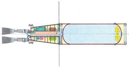
lander concept definition studies.3 Three Spaceship Discovery design reference missions are presented to develop
design requirements: Missions to the Jovian moons Ganymede and Callisto and a mission to Earth’s Moon that
would be used to flight test the lander prior to using it on a deep space mission. Ganymede mission requirements
were most stressing for the design and sized the vehicle. Propellant can be offloaded to perform missions to Callisto
and Earth’s moon. Design requirements, mission profiles, mass properties, performance data, and configuration
layouts are presented for the LM1 crew lander. This design is a proposed solution to land humans on the Jovian
moons Ganymede and Callisto based on reliable and proven technology. It can be flight tested on Earth’s Moon.
The LM1 design and operations concept stress safety and redundancy and feature abort and rescue capabilities.
Engineering Main LH2 Propellant Main LH2 Propellant Service Module Crew Module
Module (EM) Core Tank (CT) (4) Drop Tank (DT) (12) (SM) (CM)
a. Main Ship –
Side View 5-Port Docking Mars Lander Modules
Module (DM) LM2, LM3 (DRMs 2, 3)
Closed Brayton Cycle
(CBC) Electrical
Generation Systems (3) Very Low Boil-off Artificial Gravity
Cryo. Retention Sys. (AG) Centrifuge
Bimodal Nuclear Abort Propulsion Galactic Cosmic Ray
Thermal Rocket System (APS) (GCR) Biological
(NTR) Engines (3) Engine Shield (LH2 & H2O)
Ganymede, Callisto, Reentry
Deployable Solar / b. Side View Cutaway – Earth’s Moon Lander Module
Thermal Shades (2) Key Design Features Module LM1 (DRMs 1, 5, 6) (RM)
FIGURE 1. Spaceship Discovery Conceptual Architecture for Human Solar System Exploration.
II. Mission Requirements
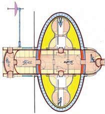
Figures 2a-2d depict the various Spaceship Discovery configurations corresponding to the design reference
missions that were used to develop design requirements for the LM1 Crew Exploration Lander.
A. Design Reference Mission 1 (DRM 1) – Lunar Flight Test/Crew Training
This DRM is used to flight test spaceship Discovery prior to flying deep space missions and train flight crews.
LM1 landers can be flight tested in the similar environment of Earth’s Moon prior to Jupiter missions. Spaceship
Discovery departs the 556 km circular Earth parking orbit with the Trans-Lunar Injection (TLI) burn using the three
nuclear thermal rocket (NTR) engines on the main ship as shown in Fig. 2c. The main ship is reusable for this
mission. Six crew members and three redundant LM1 landers are carried. After a 3.4 day transit, the Lunar Orbit
Insertion (LOI) burn places the vehicle into a 185 km circular lunar orbit. A stay time of 180 days in lunar orbit was
chosen to approximate DRMs 5-6 mission durations at Jupiter and size Discovery’s on-board consumables. With
three landing missions in succession, two landing parties could explore the surface of the moon for a total of 90 days
to train crews prior to Ganymede or Callisto surface exploration missions. At the conclusion of the landing missions,
the TEI burn propels Spaceship Discovery into the 3.4 day return transfer orbit, and the Earth Orbit Insertion (EOI)
burn places the vehicle into Earth parking orbit as shown in Fig. 2d. Crew and samples return to Earth in the RM.
B. Design Reference Mission 5 (DRM 5) – Callisto Exploration
This mission has a duration of four years, with one year, nine month transits and a six month wait time in the
Jovian system. DRM 5 has a crew complement of four. Spaceship Discovery escapes the 556 km circular Earth
2
American Institute of Aeronautics and Astronautics
parking orbit (Trans-Jupiter Injection, TJI) using nine NTR engines on main ship and boosters. The twin, strap-on
boosters depicted in Fig. 2a enable high-energy missions to Mars and Jupiter. For design commonality, each booster
utilizes the same modules as the main ship, with a single EM and two CTs. Main propellant DTs can be clustered
around booster CTs, with the number of DTs tailored to mission requirements. During the TJI burn, the boosters will
cross-feed propellant to the three NTR engines on the main vehicle as well as supplying the six NTR engines on the
boosters. After booster propellant is expended, the boosters are jettisoned and the main ship briefly accelerates using
its three NTR engines to ensure that the boosters miss the rendezvous with Jupiter. The boosters are disposed of into
a solar orbit, and residual booster propellant is vented over time to raise their orbit periapsis above 1.0 AU. The
main ship transfer orbit apoapsis is 6.7 AU. Callisto Orbit Insertion (COI) includes two burns: A propulsive capture
burn into an elliptical Jupiter orbit with periapsis at the radius of Callisto (1.884 M km), and a propulsive capture
into a 185 km circular parking orbit around Callisto with a 3.965 degree plane change. Callisto’s orbit is the farthest
from Jupiter of the Galilean moons, but lander shielding will still be needed for radiation dose rates to be tolerable to
the crew. Three redundant LM1 landers are carried. The first LM1 lands with two astronauts, leaving two astronauts
in orbit. After a stay of 30 days, the crew departs the surface and docks with the main ship. The other two astronauts
then take their 30 day turn on the surface in a second LM1. The third LM1 is always in standby and can be flown by
one astronaut to rescue either landing party if it became stranded. The TEI burn is a direct escape from Callisto
orbit and Jupiter, and propels the ship into the inbound transfer orbit. (Fig. 2d). Discovery has insufficient propellant
left for propulsive capture at Earth. The Earth Trajectory Injection (ETI) burn is performed at 900,000 km (35.3 hrs)
from Earth after the ship is within Earth’s 924,133 km activity sphere radius. The crew enters the RM and separates
from the main ship at 800,000 km (31.3 hrs) from Earth, aimed at a periapsis altitude of 122 km. The crew performs
a hyperbolic reentry and landing in the RM. The ETI burn reduces RM entry velocity from 14.6 km/s to 13.0 km/s.
After RM departure, the main ship performs a 434 m/s burn to increase periapsis altitude to 1,000 km, enabling a
posigrade hyperbolic pass high above the atmosphere. The main ship is disposed of into solar orbit with apoapsis
greater than 3.0 AU and periapsis greater than 1.0 AU to prevent any chance of it impacting Earth.

C. Design Reference Mission 6 (DRM 6) – Ganymede Exploration
     Ganymede is the largest moon of Jupiter, and at 5,262 k m in diameter, is the largest moon in the solar system. It
is larger than Mercury or Pluto. DRM 6 has the same overall mission profile as DRM 5 except that Ganymede is the
targeted moon. It is postulated that Ganymede could be briefly visited with sufficient radiation shielding. Ganymede
Orbit Insertion (GOI) includes two maneuvers: A propulsive capture into an elliptical Jupiter orbit with periapsis at
the radius of Ganymede (1.070 M km), and a propulsive capture into a 185 km circular parking orbit around
Ganymede with a 0.865 degree plane change. Three redundant LM1 landers are carried and the four crewmembers
explore the surface of Ganymede. The TEI burn is a direct escape from Ganymede orbit and Jupiter. The inbound
transit, ETI burn, RM hyperbolic entry, and disposal of the main ship into solar orbit are the same as for DRM 5.

                    III.    Design of LM1 Lunar Crew Exploration Lander Vehicle

A. Design Overview and Assumptions
     The LM1 crew lander utilizes only vacuum propulsive braking and is designed to land on the airless Jovian
moons Ganymede and Callisto. It is also designed to be flight tested on Earth’s Moon. It provides two-way
transportation for a nominal two-person crew between the parking orbit and the surface, and also functions as a
habitat and rover vehicle. The design incorporates a layer of water in the crew cabin walls to shield the crew from
Jupiter’s intense radiation environment. The LM1 crew lander normally carries two astronauts, with an endurance of
30 days on the surface (including margin) and seven days for ascent and contingencies. It can support three
astronauts for rescue missions, albeit with reduced endurance. It can achieve orbit with three crew, three space suits,
three emergency life support system units, and a contingency sample (20 kg vs. the normal sample allocation of 125
kg). The LM1 lander extensively utilizes lightweight composite structures to maximize performance and minimize
overall system mass. It is envisioned that advanced composite materials used for crew habitation areas will be “dual-
mode,” and provide radiation protection shielding as well as structural integrity.4 It utilizes liquid hydrogen and
liquid oxygen (LH2/LO2) propellants in the Descent Stage (DS) and storable monomethyl hydrazine/nitrogen
tetroxide (MMH/NTO) propellants in the AS. The LM1 lander has a 6-axis reaction control systems (RCS) for
attitude control and rendezvous and docking translation maneuvers. The lander RCS engines utilize storable,
hypergolic MMH/NTO propellants. The LM1 has functionality and flight profiles similar to the Apollo Lunar
Module, but is larger, with higher performance and much higher endurance. Its design incorporates Altair,3 Space
Shuttle,5, 6 MMH/NTO engines,7 and Apollo Lunar Module 8-11 design data with upgrades for recent advances in
materials and subsystems. The LM1 service life is three years (one-year assembly in low-earth orbit plus one-half of
                                                         3
                                 American Institute of Aeronautics and Astronautics
the duration of DRMs 5 or 6). The design of LM1 landers is in keeping with the design philosophy for high mission
redundancy. Aborts are extensively considered in the design and operations concept. The LM1 crew lander is
designed for abort-to-orbit (ATO) during all parts of the powered descent, where the DS is jettisoned and the AS
returns to orbit. Multiple landers enable multiple exploration landing mission attempts and also enable rescue
missions if a landing party were to become stranded on the surface. LM1 configuration layouts are presented in Figs.
3 and 4 and design data are presented in Tables 1 and 2. Lander ascent and descent flight performance was
determined using a 2-D trajectory simulation with a spherical gravitational potential. Performance calculations
included 1% flight performance reserve (FPR) on GV. Flight performance data for Ganymede, Callisto, and Earth’s
Moon simulations are presented in Tables 3 and 4. The Ganymede mission requirements were most stressing for the
design and sized the vehicle. Callisto and Earth’s Moon missions had similar GV requirements. The Callisto mission
was the least stressing. Propellant can be offloaded to perform the Callisto and Earth’s moon missions as shown in
Table 4. Flight performance plots for the Ganymede sizing case are presented in Figs. 5-14. Performance plots for
the Callisto and Earth’s Moon simulations are very similar to the Ganymede case and are omitted for brevity.
B. Design of Descent Stage (DS)
The overall design of the DS is common to the LM2/LM3 Mars landers, with the same basic layout that utilizes a
central thrust cylinder to efficiently carry loads. The DS airlock, cargo bay, and fuel cell consumables tanks are the
same as those used on the LM2 Mars lander. The DS landing legs and traversing wheels utilize the same kinematics,
geometry, and mechanisms as the LM3 Mars lander. Structural thicknesses have been reduced to account for
reductions in flight loads between the Mars and moon missions. Landing gear struts have 0.6 m of shock absorbing
stroke and another 0.6 m of adjustability to level the vehicle. The landing gear struts have wheels to enable the LM1
to traverse the surface at the relatively slow pace of 90 m per hour, using 1.0 kW for the drive motors. The LM1 can
nominally traverse up to 1.08 km per 24 hour period, assuming 12 hours for stops and crew rest periods each day.
Rover wheel motor drive power calculations are based on Mars Exploration Rover design data.12 The DS houses
propellant, pressurization, fuel cells and their consumables tanks (including breathing oxygen), and eight gimbaled,
throttleable 12.2 kN RL-10 based descent engines that are spaced at 45-degree intervals around the base of the thrust
cylinder. Engines are throttleable between 100% and 30% thrust and are sized for single engine-out considerations.
In the event of an engine out, the corresponding opposite engine would be shut down to balance the thrust. Multiple
descent engines are shut down during the powered descent, in groups of two, to maintain proper thrust and balance.
The personnel airlock in the DS is accessible by tunnel from the AS crew cabin. There is a cargo bay on the opposite
side of the DS as the airlock, with a capacity of 500 kg of payload for various types of exploration equipment and
science experiments. Descent and surface electrical power is provided by fuel cells, whose design is based on Apollo
fuel cells.11 LM1 fuel cells produce up to 4.1 kW peak power. Lander wheel drive motors consume 1 kW, heaters 1
to 2 kW, and a maximum of 1 kW are consumed by the Equipment Cooling and Life Support System (ECLSS),
Guidance, Navigation and Control (GN&C) System, communications, and lighting and habitat loads. Reactants are
carried to support an average duty cycle of 3 kW. Eight storage tanks hold shielding water for the crew cabin.
C. Design of Ascent Stage (AS)
The design of the AS crew cabin, thrust cylinder, and airlock tunnel is common to the LM2 Mars lander, with the
same basic layout that utilizes a central thrust cylinder to efficiently carry loads. The crew cabin has 29 m3 of usable
inner moldline volume. It has a pressurized tunnel connecting it to the airlock in the DS. After landing, 1,722 kg of
water is pumped from the DS into a 4.0 cm thick shielding layer in the crew cabin inner wall. It provides 4 gm/cm2
of radiation shielding, affording the same protection to the crew as that provided by the Crew Module on the main
ship. This water must be drained into storage tanks in the DS to lighten the AS sufficiently for the ascent to orbit.
The AS crew cabin functions as flight deck and habitat for the two person crew. The two crew members stand in
front of the control console. Two large angled windows provide excellent visibility for approach and landing. The
habitat portion of the cabin contains two bunks, a computer table, a kitchen with dining table and chairs, and
hygiene facilities including a toilet, sink, and shower. The AS has four unpressurized external bays: A forward bay
for the airlock tunnel and GN&C and communications equipment, an aft bay for batteries, ECLSS equipment and
consumables tanks (breathing oxygen and water), and right and left side bays for main and RCS propellant tanks.
The four unpressurized bays and the central crew cabin are covered with thermal blankets and heavily insulated
against the cold environment. The central thrust cylinder, below the crew cabin, houses eight 3.33 kN fixed-thrust
ascent engines and main and RCS helium pressurization tanks. Ascent engines are sized for single engine-out
considerations. In the event of an engine out, the corresponding opposite engine will be shut down to balance thrust.
Sixteen 0.77 kN RCS thrusters are arranged in four groups of four. Ascent electrical power is provided by solar
arrays and batteries. Solar arrays and radar and communications antennas are attached to the exterior of the AS.
4
American Institute of Aeronautics and AstronauticsBooster Mated to
Main Ship
Boosters (2) Used
for Trans-Jupiter
Injection Burn
a. DRMs 5 or 6 – Assembly in Earth Parking Orbit in Preparation for Trans-Jupiter Injection
b. DRMs 5 or 6 – Outbound Transit to Jovian System and Insertion into Callisto or Ganymede Orbit
c. DRMs 5 or 6 – In Orbit around Callisto or Ganymede, Ready for Landing Missions
DRM 1 – Trans-Lunar Injection, Outbound Transit, Lunar Orbit Insertion, and Ready for Landing Missions
d. DRMs 5 or 6 – Trans-Earth Injection, Inbound Transit, and Earth Trajectory Injection
DRM 1 – Trans-Earth Injection, Inbound Transit, and Earth Orbit Insertion
FIGURE 2. Design Reference Mission Configurations.
5
American Institute of Aeronautics and AstronauticsCrew Cabin w/
Tunnel to 4 cm Water
Airlock in Shielding Layer
DS Thermal
Blanketing Over
LSS LO2 Stowed Landing
Tank (2 pl) Gear (4 pl)
LSS H2O
Tank (2 pl)
ECLSS
Equip.
Cargo Bay
Main Prop.
LH2 Tank Bay
Main Prop.
LO2 Tank
Reflective DS Main
Thermal Propellant
Side View Cutaway, Ascent Foil around Descent Stage Cutaway through LO2 Tank
and Descent Stages Lander Base Landing Gear Bays (Gear Stowed)
AS Main Crew Cabin Including
Propellant Flight Deck & Habitat
NTO Tank
(2 pl) AS Main
Propellant
MMH Tank
(2 pl) DS Main
Propellant Bio Shield
Fuel Cell/ LSS LH2 Tank
Supercrit. LH2 Water Stg.
& LO2 Tanks Tanks (8 pl)
(2 sets) DS Main
Propellant &
Bio Shield
Water
Pressurization
Tanks (4 pl)
DS Thrust DS Main Gimballed Articulated
Cylinder Propellant Descent Drive Wheel
Primary LO2 Tank Engines (8 pl) (8 pl)
Structure
Front View Cutaway, Descent Stage Cutaway through
Ascent and Descent Stages Landing Gear Bays (Gear Deployed)
FIGURE 3. LM2 Crew Lander Configuration Drawings – Elevation Views.
6
American Institute of Aeronautics and AstronauticsDS Main Propellant & Surface
Bio Shield Water He Access
LSS H2O
Pressurization Tanks Door Pair
Crew Bunk Tks (2 pl) DS Main (4 pl) (2 pl)
(2 pl) Propellant
Crew Habitat LH2 Tank
Including Cargo Bay
Sleeping, Eating, Fuel Cell/ LSS
and Hygene Supercrit. LH2
Facilities Tanks (2 pl)
Main Propellant
and RCS Tank
Bay (2 pl)
Flight Deck Tunnel to
and Main Airlock in DS
Windows DS-AS
Air Explosive
Lock Separation
Ascent Stage Upper Level Descent Stage Upper Level Bolts (6 pl)
showing Crew Cabin. (Landing Gear Shown Stowed)
DS Main Bio Shield
DS Main Water Stg.
ECLSS Engines
Propellant Tanks (8 pl)
Main Propellant Bay (8 pl)
LO2 Tank
Pressurization AS Main
Tanks (4 pl) Engines
(8 pl)
Cargo
Bay
Fuel Cell/ LSS
Supercrit. LO2
Tanks (2 pl)
RCS
Prop.
Press.
Tanks
(2 pl)
Air
Fuel Cell Lock
(4 pl)
Main
Propellant &
RCS Tank RCS Thruster
Bay (2 pl) Ascent Stage Lower Level Quad (4 pl) Descent Stage Lower Level
Propulsion and Systems Bays (Landing Gear Shown Deployed)
FIGURE 4. LM2 Crew Lander Configuration Drawings – Cross Section Views.
7
American Institute of Aeronautics and AstronauticsTABLE 1. LM1 Design Assumptions for Life Support Consumables.
Ascent Descent LM1
Stage Stage Overall
Design Assumptions (kg/man-day)
Breathing Oxygen 1.00 1.00
Water 3.00 7.50
Dried & Condensed Food 2.00 2.00
Endurance
Total Man-Days 14 60 74
Total Days for 2 Crewmembers 7 30 37
Consumables Mass (kg)
Breathing Oxygen 14 60 74
Water 42 450 492
Dry Food 28 120 148
Add’l. Fuel Cell Reactants Available 232 232
Total Consumables 84 862 946
TABLE 2. LM1 Dimensions and Mass Properties (Propellants Shown for Ganymede Sizing Case).
Descent Ascent
Ascent Descent Total for Rescue Nominal
Stage 1 Stage 1 Descent 1 Ascent 2 Ascent 3
Dimensions (m)
Length Overall 4.3 5.1 9.4 4.3 4.3
Diameter 7.0 7.5 7.5 7.0 7.0
Masses (kg)
Payload 380 500 880 20 125
Crew Shielding Water 1,722 1,722
(2) PLSS in Airlock 90 90
Crew, Suits, ELSS 240 240 360 240
Structure & Insulation 605 1,079 1,684 605 605
Propellant & Press. Tanks 344 491 834 344 344
Landing Gear 159 159
Drive Motors and Wheels 119 119
ECLSS, Power, & Avionics 454 525 979 454 454
Main Engine 111 266 377 111 111
RCS 216 216 216 216
Dry Mass Margin (15%) 259 396 655 259 259
LSS/Fuel Cell Consumables 84 862 946 84 84
RCS Propellant (Usable) 432 432 216 216
Operating Empty Mass 3,124 6,209 9,333 2,668 2,653
Main Propellant (Usable) 3,382 9,250 12,632 3,382 3,382
Total Mass 6,506 15,459 21,965 6,050 6,035
4
Non-Prop/Non-Cons. Mass Fract. 0.361 0.320 0.332 0.349 0.347
1
Nominal descent: Two crewmembers, space suits & ELSS units, and 500 kg payload.
2
Three crewmembers, space suits & ELSS units, and 20 kg contingency sample.
3
Two crewmembers, space suits & ELSS units, and 125 kg sample payload.
4
(Payload + Shielding + Struct./Insulation + Engines & Subsystems (Incl. Prop. Residuals)) / Total Mass
8
American Institute of Aeronautics and AstronauticsTABLE 3. LM1 Mission Parameters.
Target Planetary Body Ganymede Callisto Moon Powered Descent K - True
Planetary Parameters Initiation (PDI) K Anomaly, PDI
Point to Landing
Radius at Surface (km) 2,631 2,410 1,738
Equatorial Rotation (m/s) 26.7 10.5 4.6 Landing
3 2 Point
Gravitational Parameter (km /s ) 9,887 7,179 4,903
Gravity at Surface (m/s2) 1.428 1.237 1.620
Circ. Parking Orbit Parameters
Parking Orbit Radius (km) 2,816 2,596 1,923
Parking Orbit Altitude (km) 185.4 185.4 185.4 Descent Descent
Orbital Velocity (m/s) 1,874 1,663 1,597 Transfer Transfer
Burn Orbit
Descent Parameters a. Descent to Surface
GV for Transfer Burn (m/s)
1
221 203 197 K - True Anomaly,
Periapsis Altitude (PDI) (km) 15.2 15.2 15.2 Launch to K
Circulariz. Orbit Circular-
Inertial Velocity at PDI (m/s) 1,968 1,749 1,711 ization Burn
Burn
Relative Velocity at PDI (m/s) 1,941 1,739 1,706
True Anomaly at Landing (deg) 11.9 10.4 13.9
Ascent Parameters
Relative Vel. at Burnout (m/s) 1,938 1,707 1,628
Rel. Vel. at 185 km Alt. (m/s) 1,876 1,663 1,600
Launch
GV for Circulariz. Burn 2 (m/s) 335 265 258 Point Parking
Ascent True Anomaly (deg) 37.7 38.0 32.3 Orbit
1
Includes 25 m/s maneuvering, 5 deg. plane change, 1% flight perf. reserve (FPR). b. Ascent to Orbit
2
Includes 100 m/s maneuv., 5 deg. plane change, +30 degree incl., and 1% FPR. FIGURE 5. LM1 Mission Profiles.
TABLE 4. LM1 Flight Performance Data.
Target Planetary Body Ganymede (DRM 6) Callisto (DRM 5) Earth’s Moon (DRM 1)
Nominal Rescue Nominal Rescue Nominal Rescue
Lander Mission Profile
Descent 1 Ascent 2 Descent 1 Ascent 2 Descent 1 Ascent 2
Deorbit & Ascent & Deorbit & Ascent & Deorbit & Ascent &
Major Propulsive Burns
Descent Circularize Descent Circularize Descent Circularize
Required Delta Velocity (km/s)
Orbital Maneuvering 3 0.219 0.313 0.201 0.246 0.195 0.240
Powered Descent or Ascent 1.941 1.876 1.739 1.663 1.706 1.600
Gravity Losses 0.255 0.319 0.201 0.315 0.308 0.431
Flight Performance Reserve (FPR) 0.034 0.022 0.027 0.019 0.035 0.018
Total 2.450 2.530 2.167 2.242 2.244 2.289
Performance Parameters
Specific Impulse (I SP) 448 316 448 316 448 316
Mass Ratio (M i / M f ) 1.750 2.268 1.641 2.066 1.670 2.097
Burn Propellant Fraction 0.429 0.559 0.391 0.516 0.401 0.523
4
Initial Thrust / Weight 2.372 2.315 2.763 2.960 2.163 2.222
Final Thrust / Weight 4 4.151 5.250 4.535 6.114 3.611 4.660
Mass (kg)
Operating Empty Mass 9,333 2,668 9,286 2,644 9,296 2,649
Main Propellant 12,632 3,382 10,334 2,819 10,824 2,906
Total Mass 21,965 6,050 19,620 5,463 20,120 5,555
1 2
Nominal descent (2 crewmembers) is sizing case. Rescue ascent (3 crewmembers) is sizing case.
3
Includes a plane change of 5.0 degrees during both descent and ascent.
4
Referenced to the acceleration of gravity at surface: (1.428 m/s2 Ganymede; 1.237 m/s2 Callisto; 1.620 m/s2 Earth’s Moon).
9
American Institute of Aeronautics and Astronautics20
16
Entry Interface Altitude
Altitude (km)
12
8
4
0
1,800 1,600 1,400 1,200 1,000 800 600 400 200 0
Velocity (m/s)
FIGURE 6. LM1 Ganymede Powered Descent Trajectory Parameters – Axial Velocity vs. Altitude.
1,000
900
800
700
600
Altitude (m)
500
400
300
200
100 m Hover Altitude 100
0
90 80 70 60 50 40 30 20 10 0
Velocity (m/s)
FIGURE 7. LM1 Ganymede Powered Descent Trajectory Parameters – Axial Velocity vs. Altitude.
1.5
1.0
Altitude (km)
0.5
100 m Hover Altitude
0.0
544.5 545.0 545.5 546.0 546.5 547.0 547.5
Downrange Displacement from Entry Interface (km)
FIGURE 8. LM1 Ganymede Powered Descent Trajectory Parameters – Altitude vs. Downrange Displacement.
10
American Institute of Aeronautics and Astronautics10.00
Flight Path Angle
0.00
Thrust Vector or Flight Path Angle (Deg.)
Timed
-10.00 Hover
Phase
-20.00
-30.00 Thrust Vector Angle
-40.00
Soft
-50.00
Landing
-60.00 Phase
-70.00
-80.00
-90.00
0 100 200 300 400 500 600 700
Time From Entry Interface (s)
FIGURE 9. LM1 Ganymede Powered Descent Trajectory Parameters – Flight Path and Thrust Vector Angles vs. Time.
0.50
Timed
0.40 Hover
Phase
Acceleration (Earth g's)
0.30
Soft
Landing
Phase
0.20
0.10
0.00
0 100 200 300 400 500 600 700
Time From Entry Interface (s)
FIGURE 10. LM1 Ganymede Powered Descent Trajectory Parameters – Axial Acceleration vs. Time.
100
Timed
80 Hover
Phase
60
Force (kN)
Soft
Landing
Phase
40
20
0
0 50 100 150 200 250 300 350 400 450 500 550 600 650 700
Time From Entry Interface (s)
FIGURE 11. LM1 Ganymede Powered Descent Trajectory Parameters – Thrust Force vs. Time.
11
American Institute of Aeronautics and Astronautics200
Orbital Altitude
Horizontal Velocity -
150 Includes 26.7 m/s
Equatorial Rotation
Vertical Velocity
Altitude (km)
100
Burnout
50
0
0 500 1,000 1,500 2,000 2,500
Velocity (m/s)
FIGURE 12. LM1 Ganymede Ascent Trajectory Parameters – Altitude vs. Inertial Velocity Components.
200
Orbital Altitude
150
Altitude (km)
100
Burnout
Vertical Acceleration 50 Horizontal Acceleration
0
-5 0 5 10
2
Acceleration (m/s )
FIGURE 13. LM1 Ganymede Ascent Trajectory Parameters – Altitude vs. Inertial Acceleration Components.
90 Burnout
80
Angle from Horizontal (Degrees)
70
60
50
40
30 Flight Path Angle
20 Thrust Vector Angle
10
0
0 50 100 150 200 250 300 350 400 450 500 550 600
Elapsed Time From Ignition (s)
FIGURE 14. LM1 Ganymede Ascent Trajectory Parameters – Flight Path and Thrust Vector Angles vs. Time.
12
American Institute of Aeronautics and AstronauticsIV. Mission Profiles
The key events of the LM1 mission description are presented pictorially in Figs. 15a-15h.
A. Launch from Earth to LEO Assembly Orbit
The Spaceship Discovery design is modular and assembled in a circular, 556 km Earth orbit. Subassemblies are
up to 33.0 m length x 8.4 m in diameter, with a maximum mass of 50 metric tons (MT), including fairing, adaptors,
and airborne support equipment. Two 21.8 MT LM1 landers can be launched simultaneously as shown in Fig. 15a.
Launch vehicles are assumed to be enhanced versions of the current Evolved Expendable Launch Vehicles
(EELVs).13, 14 Once in the parking orbit, landers dock to the Spaceship Discovery docking module as shown in Fig.
15b. Vehicle assembly and outfitting will be completed and the main propellant tanks will be topped off. The Jupiter
mission crew will board, make preparations for the Trans-Jupiter Injection burn, and depart Earth orbit for Jupiter.
B. Outbound Transit
Figure 15c shows three LM1 landers and a Reentry Module docked to the main ship docking module. During
the 21 month DRM 5/6 outbound transit from Earth to Jupiter the LM1 landers will be kept in a hibernation mode to
conserve power. Periodic automated checkouts of lander systems will be performed. Spaceship Discovery utilizes a
Very Low Boil-Off System, with refrigeration plants and space radiator panels, to remove heat from on-board
cryogenic propellant and consumables tanks to minimize boil-off. Chilled helium gas is circulated through
cryocoolers to remove heat from these tanks. This system will be connected by umbilicals to the three LM1 landers
to cool liquid and supercritical H2 and O2 tanks in the descent stages. After insertion into the 185 km altitude circular
parking orbit, the landers are powered up and thorough systems checks are performed in preparation for landing.
C. Descent from Parking Orbit to Surface
The crew enters the LM1 and the lander undocks from the main ship. Landing gear are deployed and locked.
LM1 landers are designed to operate from parking orbits inclined up to 30 degrees to the equator, and can execute a
plane change of up to 5 degrees during descent. This will permit significant flexibility in surface targeting. A deorbit
burn is accomplished using the descent engines as shown in Fig. 15d. This maneuver inserts the lander into an
elliptical transfer orbit whose periapsis is 15.2 km. The powered descent (PD) is initiated at this point and continues
to 100 m above the surface at constant thrust/weight (T/W) of 2.5. PD continues with hovering (T/W = 1.0) at 100 m
altitude, with sufficient propellant carried to hover for a maximum of 60 seconds to locate and avoid obstacles. PD
concludes with a soft landing (Tables 3 and 4 and Figs. 5a, 6-11, and 15e). In the event of a landing abort, the LM1
descent stage will be jettisoned and the ascent engines will ignite and propel the ascent stage on an ascent trajectory
that returns it to the 185 km altitude Spaceship Discovery parking orbit. An abort-to-orbit is available during the
entire PD duration. The LM1 abort-to-orbit performance and trajectories will be detailed in future work.
D. Surface Operations
The LM1 lander provides a roving habitat for the crew. It provides biological shielding to the crew from the
hazardous radiation environment near Jupiter using a combination of advanced “dual-mode” composite materials
and a layer of shielding water in the crew cabin. It is designed to traverse up to 30 km during its 30 day surface
exploration mission using its powered wheels. It is envisioned that the crew will spend most of their 30 day mission
inside the LM1 shielded habitat and only make brief extra vehicular activity (EVA) sorties due to the high radiation
environment. Figure 15f shows the LM2 crew lander in its landed configuration. A ladder has been extended from
the airlock to permit the crew to access the surface for EVA. LM1 surface operations will be detailed in future work.
E. Ascent to Parking Orbit, Rendezvous, and Docking
Before liftoff from the surface, the crew drains the 1,722 kg of shielding water from the AS crew cabin shield
tank into the DS storage tanks, and also leaves their portable life support system backpacks in the airlock in order to
lighten the AS. The LM1 ascent stage launches from the descent stage as shown if Fig. 15g. The AS is designed to
ascend to the parking orbit from latitudes of up to + 30 degrees from the equator. The eight ascent engines burn at
constant thrust until sufficient velocity is achieved and they are shut down. The AS then coasts up to the parking
orbit altitude of 185 km. At this point, the ascent engines fire again to circularize the orbit and, if required, execute a
plane change of up to 5 degrees (Tables 3 and 4 and Figs. 5b and 12-14). The AS then maneuvers in orbit using the
ascent engines and RCS to rendezvous and dock with the Spaceship Discovery main ship as shown in Fig. 15g. The
main ship could also rendezvous and dock with the AS in the event of a failure of the AS after it has reached parking
orbit. The crew transfers to the main ship and the ascent stage is deorbited using its residual propellants.
13
American Institute of Aeronautics and Astronauticsa. Launch Configuration b. Orbital Assembly
c. Outbound Transit d. Deorbit Burn
FIGURE 15. Mission Configurations.
14
American Institute of Aeronautics and Astronauticse. Powered Descent f. Surface Operations
g. Ascent to Parking Orbit h. Rendezvous and Docking with Main Ship
FIGURE 15. Mission Configurations, Continued.
15
American Institute of Aeronautics and AstronauticsV. Enabling Technologies
Continued development of key enabling technologies will be necessary for the implementation of the LM1 crew
lander vehicle. These key enabling technologies are listed below:
(1) Reliable launching of 50 MT subassemblies , 33.0 m long x 8.4 meters in diameter, into LEO parking orbits.
(2) Lightweight “dual-mode” advanced composite materials for structures that incorporate radiation protection.
(3) Highly reliable retention systems for long-term, low-loss storage of cryogenic liquids (LH2 and LO2).
(4) Support equipment for long-duration human habitation and surface exploration of airless moons, including
space suits, power generators, life support systems, communications gear, and scientific equipment. This will
enable the crew to conduct extensive and detailed scientific explorations of Ganymede and Callisto.
VI. Conclusion
The Spaceship Discovery LM1 lander design is a proposed solution to land humans on the large Jovian moons
Ganymede and Callisto. The LM1 can be flight tested on Earth’s Moon. All maneuvers necessary for the Ganymede
or Callisto landing can be practiced in the similar environment of the nearby Moon. The LM1 functions as lander
vehicle, habitat, and rover. It provides two-way transportation for a nominal two-person crew between orbit and the
surface, life support for a surface stay of up to 30 days, and surface mobility of up to one kilometer per day. It also
provides biological radiation shielding for the crew. The LM1 design is based on reliable and proven technologies
from the Space Shuttle and the Apollo Lunar Module. It incorporates the results of recent NASA Altair lunar lander
design studies. To reduce development cost, the LM1 lander features a geometrical layout, structural concept, crew
cabin, airlock, and airlock access tunnel, and landing gear that are common to those of the Spaceship Discovery
LM2/LM3 Mars landers. The LM1 lander design and operations concept stresses safety and redundancy and is in
keeping with the Spaceship Discovery design philosophy for high mission redundancy: Aborts modes and rescue
capabilities are extensively considered in the design. The LM1 is designed for abort-to-orbit (ATO) during all parts
of the powered descent. Multiple landers enable multiple exploration landing mission attempts during high value,
deep space missions and also enable rescue missions if a landing party were to become stranded on the surface.
References
1
Benton, Sr., M. G., “Spaceship Discovery – Vehicle Architecture for Human Exploration of Moon, Mars, and Beyond,”
AIAA-2006-7445, AIAA Space 2006 Conference, San Jose, CA, 2006.
2
Benton, Sr., M. G., “Crew and Cargo Landers for Human Exploration of Mars – Vehicle System Design,” AIAA-2008-
5156, AIAA 2006 Joint Propulsion Conference, Hartford, CT, 2008.
3
Benton, Sr., M.G., Caplin, G., Reiley, K., Donahue, B., Messinger, R., and Smith, D.B., “Boeing Design Trades in Support
of the NASA Altair Lunar Lander Concept Definition,” AIAA-2008-7798, AIAA Space 2008 Conference, San Diego, CA, 2008.
4
Sen, S., Schofield, E., Carranza, S., O’Dell, S., “Development of Multifunctional Radiation Shielding Materials for Long
Duration Human Exploration Beyond the Low Earth Orbit,” 58th International Astronautical Congress, Hyderabad, India, (IAC-
07-C2.4.02), 2007.
5
Morita, W.H., (ed.), “Space Shuttle System Summary,” Rockwell International Corp., Downey, CA, May, 1980.
6
Goree, J.F., “Shuttle Systems Weight & Performance Monthly Status Report,” (NASA-TM-84748), NASA, May 18, 1982.
7
Wade, M., References for Aerojet HiPAT Thrusters and Space Shuttle OME, Encyclopedia Astronautica Online Reference,
URL: http://www.astronautix.com/props/index.htm/ [cited 20 April 2008].
8“
Apollo Program Summary Report, App.C – Apollo Spacecraft Weights,” (NASA-TM-X-68725), NASA, 1975, pp. C1-C4.
9“
Apollo 11 Lunar Landing Mission Press Kit,” (NASA Release No. 69-83K), NASA, 1969, pp. 86-107.
10 “
Apollo 7 Mission Press Kit,” (NASA Release No. 68-168K), NASA, 1968, pp. 25-30.
11
Heitchue, R.D., (ed.), Space Systems Technology, Reinhold Book Corp., New York, 1968, pp. 224-230.
12
(No author listed) “Mars Exploration Rover: Rover Design, Drive System and Power and Electronic Systems,” Wikipedia
Online Reference, URL: http://en.wikipedia.org/wiki/Mars_Exploration_Rover [cited 22 June 2008].
13
Covault, C., “Launch Vehicles: Trial by Fire,” Aviation Week and Space Technology, Volume 162, No. 8, February 21,
2005, pp. 48-51.
14
Scott, W.B., “Morphing Rockets: Lockheed Martin's Atlas V Could Evolve to Saturn V-Class Performance,” Aviation
Week and Space Technology, Volume 162, No. 25, June 20, 2005, pp. 62-63.
16
American Institute of Aeronautics and AstronauticsYou can also read