Specification for Security Fencing in State Schools - Emergency & School Security
←
→
Page content transcription
If your browser does not render page correctly, please read the page content below

Emergency & School Security

Specification for
Security Fencing in
State Schools

Version 4
January 2019
19/44530
Disclaimer: Whilst every care has been taken in the preparation of this publication, the State of
Queensland accepts no responsibility for decisions or actions taken as a result of any data, information,
statement or advice, expressed or implied, contained within. To the best of our knowledge, the content
was correct at the time of publishing.

Any references to legislation are not an interpretation of the law. They are to be used as a guide only. The
information in this publication is general and does not take into account individual circumstances or
situations.

                                                                                                            2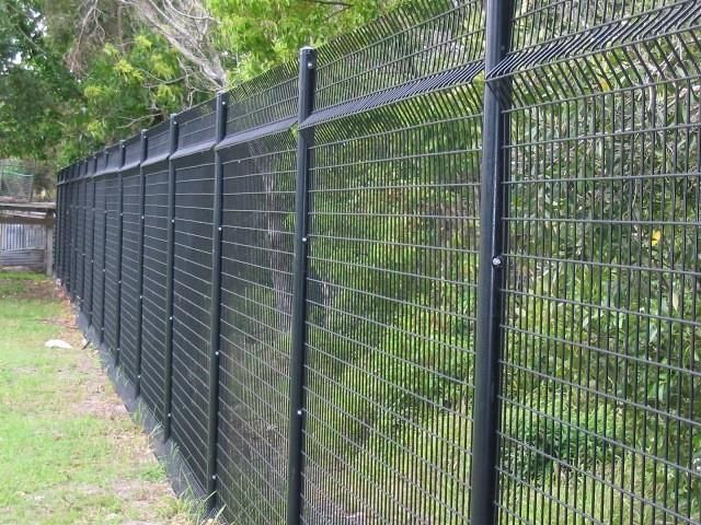
Table of Contents

Section 1 – General Information _____________________________________________________ 5
1.1        Definitions _________________________________________________________________5
1.2        Introduction _______________________________________________________________6
1.3        Types of Security Fencing _____________________________________________________7
1.4        Security Fencing - Preliminary Requirements ______________________________________8
1.5        Site Specific Requirements ____________________________________________________8
           1.5.1    Site Survey and Soil Test ____________________________________________________ 8
           1.5.2    Location of Services ________________________________________________________ 8
           1.5.3    Removal of Existing Fencing _________________________________________________ 8
           1.5.4    Light Poles, Signs and/or Sub-stations _________________________________________ 9
           1.5.5    Shrubs and Foliage ________________________________________________________ 9
           1.5.6    Removal of all Rubbish _____________________________________________________ 9
           1.5.7    Emergency access points ___________________________________________________ 9
           1.5.8    Safety ___________________________________________________________________ 9

Section 2 – General Requirements for Installation ______________________________________ 10
2.1        Requirements for Pre Treatment and Coating ____________________________________10
           2.1.1    Cleaning and Chemical Pre-Treatment ________________________________________ 10
           2.1.2    Minimum Coating Requirements ____________________________________________ 10
           2.1.3    Coating Required in Corrosive Environments___________________________________ 11
           2.1.4    Paint Coating____________________________________________________________ 11

2.2        Clearance and Welding ______________________________________________________12
2.3        General Requirements for Panels ______________________________________________12
2.4        General Requirements for Gates ______________________________________________12
2.5        General Requirements for Vehicle Gates ________________________________________13
2.6        General Requirements for Posts and Post Holes __________________________________13
2.7        General Requirements for Gate Posts __________________________________________13
2.8        General Requirements for Padlocks ____________________________________________13
2.9        Site Storage and Protection __________________________________________________13
2.10       General Requirements for Returns _____________________________________________14
2.11       General Requirements for Block Walls/Celebrated Entryways _______________________14
2.11       Electricity and Water________________________________________________________14
2.12       Key Safe/Garage ___________________________________________________________14

Section 3 – Type 1 Security Fencing __________________________________________________ 15
3.1        Type 1 Security Fencing - Summary ____________________________________________15
           3.1.1    Other Information ________________________________________________________ 16

                                                                                                    3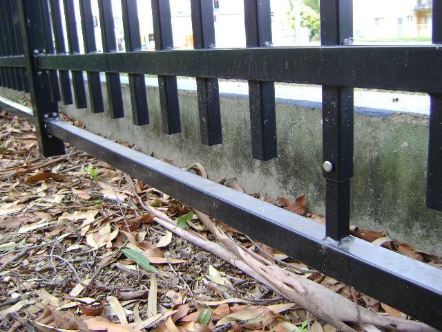
3.1.2   Panel Fittings ____________________________________________________________ 16

3.2       Type 1 Security Fencing - Posts ________________________________________________17
3.3       Type 1 Security Fencing – Gates (Hinged)________________________________________18
          3.3.1   Other Information ________________________________________________________ 19
          3.3.2   Gate Fittings_____________________________________________________________ 19

3.4       Type 1 Security Fencing - Gate Posts ___________________________________________20
3.5       Type 1 Security Fencing – Gates (Sliding) ________________________________________21
          3.5.1   Other Information ________________________________________________________ 22

3.6       Type 1 Security Fencing – Post Footings _________________________________________23

Section 4 – Type 2 Security Fencing __________________________________________________ 24
4.1       Type 2 Security Fencing – Summary ____________________________________________24
          4.1.1   Other Information ________________________________________________________ 25

4.2       Type 2 Security Fencing – Posts _______________________________________________26
          4.2.1   Other Information _______________________________________________________ 26

4.3       Type 2 Security Fencing - Gates _______________________________________________27
          4.3.1   Other Information ________________________________________________________ 28
          4.3.2   Base plates ______________________________________________________________ 28

4.4       Type 2 Security Fencing – Post Footings _________________________________________29

Section 5 – Type 3 Security Fencing __________________________________________________ 30
5.1       Type 3 Security Fencing - Summary ____________________________________________30
5.2       Type 3 Security Fencing -Posts ________________________________________________31
5.3       Type 3 Security Fencing - Gates _______________________________________________32
5.4       Type 3 Security Fencing – Post Footings _________________________________________33

Section 6 – Images _______________________________________________________________ 34

                                                                                              4
Section 1 – General Information
1.1     Definitions

Security Fencing: Fencing installed for the identified purpose of providing a physical security barrier
for the protection of school students, staff, visitors and assets.

Project Coordinator: School Security Advisor from the Department of Education Emergency &
School Security Unit, or other representative assigned to manage the fencing project.

Materials: The raw materials later used in the construction of a fence. This includes metal tubing
used for posts, rails, uprights, wooden posts, wooden rails, palings, screws, nails, welding rods.
Materials can also include protective coatings such as galvanising, powder coating, stains and paint.

Products: The items cut or constructed to form fencing products including posts, capping, fencing
panels, hinges, latches. This includes joining methods such as pressing, welding, riveting, adhesion,
nailing to complete the product. Products also include concrete for posts and surface barriers.

Galvanised Steel: Steel manufactured in accordance with AS 1450 and AS1163, in a protective
coating obtained by dipping (immersing) prepared steel in a bath of molten zinc of purity not less
than 98%.

Fencing: The combination of products designed and constructed so as to form a fence.

Blending: The procedure for ensuring post construction modifications or enhancements to the final
product are finished in the same colour and finish as the original material.

Rail: Horizontal form of fencing panels (primarily used in a Type 1 Security Fence).

Picket: Vertical upright forming fencing panels (primarily used in a Type 1 Security Fence).

Shroud: Steel coupling attached to the top and bottom of fence posts to accommodate the rails of
Type 1 Security Fencing panels.

DoE: Queensland Department of Education.

NATA: National Association of Testing Authorities of Australia.

                                                                                                          5
1.2     Introduction

This specification outlines the specific requirements for projects delivered by the Department of
Education Emergency & School Security Unit, for construction and installation of school Security
Fencing. Security Fencing is fencing installed for the identified purpose of providing a physical
security barrier to a school premise. This specification may also be considered for requirements of
fencing materials, installation and project management practices in the application of other fencing,
such as pool fences, internal safety fences and department owned residential fences.

The specification is based on Australian Standards related to the construction and installation of
relevant materials and products for Security Fencing. A summary of Australian Standards referenced
in this specification is listed below:

 AS 4750-2003             Electrogalvanized (zinc) coatings on ferrous hollow and open sections
 AS/NZS 1163-2016         Cold-formed structural steel hollow sections
 AS 1397-2011             Continuous hot-dip metallic coated steel sheet and strip - Coatings of zinc
                          and zinc alloyed with aluminium and magnesium
 AS 1725.1-2010           Chain link fabric fencing - Security fences and gates - General
                          requirements
 AS 2423-2002             Coated Steel Wire Fencing Products for Terrestrial, Aquatic and General
                          Use
 AS/NZS 4792-2006         Hot-dip galvanized (zinc) coatings on ferrous hollow sections, applied by
                          a continuous or a specialized process
 AS 4506-2005             Metal finishing - Thermoset powder coatings
 AS 1450-2007             Steel tubes for mechanical purposes
 AS/NZS 4680-2006         Hot-dip galvanized (zinc) coatings on fabricated ferrous articles
 AS/NZS 1554-2014         Structural Steel Welding
 AS 4312-2008             Atmospheric Corrosivity Zones in Australia
 AS 1742.13-2009          Manual of uniform traffic control devices - Local area traffic management
 AS 3700-2001             Masonry Structures
 AS 1170.2-2011           Structural Design Actions – Wind actions
 AS 2870-2011             Residential Slabs and Footings

Australian Standards may be            resourced    via   the   DoE    intranet    Library   Services:
https://www.saiglobal.com/online/

As noted in Sections 3, 4 and 5 of this specification, Type 1 and Type 3 Security Fencing panels and
gates are to be black in colour. Type 2 Security Fencing is to be galvanised steel or black. As the
identified purpose for Security Fencing at state schools is providing a physical measure for security,
having a fence in a colour that may be more attractive to vandals is not considered best practice.

The scope of this specification does not include advice for legislative requirements of those schools
which have, or are intending to have, swimming pools installed. Principals must seek to identify the
legislation and/or council bylaws which govern pool fencing in their respective school
precincts. School principals are responsible for the safety of staff, students and all visitors to the
school under the Work Place Health & Safety Act 2011.

                                                                                                    6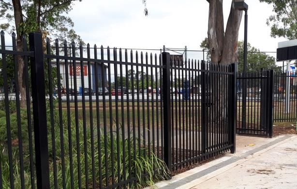
1.3    Types of Security Fencing

There are three types of fencing endorsed by DoE as Security Fencing:

                             Type 1 Security Fencing: Fencing constructed from panels comprised of
                             black spear-top steel pickets and rails, manufactured of galvanised
                             steel tube, used predominantly for areas where the boundary line is
                             accessible from a public space such as a foot path or road. Type 1
                             Security Fencing is typically 2100mm in height.

                             Type 2 Security Fencing: Fencing constructed from chain-link
                             fabric, used predominantly (but not exclusive to) for areas where
                             the school shares a boundary line with private property. Type 2
                             Security Fencing is typically 2100mm-2400mm in height.

                             Type 3 Security Fencing: Fencing constructed from welded wire mesh,
                             used predominantly (but not exclusive to) for areas not visible to the
                             general public, for example near creeks or in rural areas, including
                             sporting and agricultural areas. Type 3 Security Fencing is typically
                             2100mm-2400mm in height.

                                                                                                  7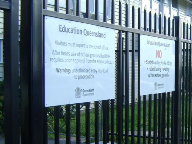
1.4 Security Fencing - Preliminary Requirements
The contractor is required to submit all quotations in accordance with the
Department of Education (DoE) tender process.
DoE Project Co-ordinators may have fencing material tested at random by NATA
registered company to ensure that all materials and treatments meet these
specifications.
Security Fencing projects are to be managed in accordance with DoE School Managed
Facility Project practices. All works carried out in the School Security Fencing Program
must conform to the Workplace Health & Safety Code of Practice 2011
Aluminium materials, or any materials other than those noted in this document must not be
used with DoE fencing projects without pre-approval from the Project Coordinator.
This specification is to be read in conjunction with the Department of Education Standing
Offer Arrangement for Security Fencing of the nominated contractor for the particular
project.
1.5 Site Specific Requirements
1.5.1 Site Survey and Soil Test
The contractor is to arrange for a Registered Surveyor to survey the school in cases
where a clearly defined property boundary is not evident and/or a dispute exists about
the location of a property boundary.
Where there is uncertainty about the integrity of the soil at the location of a proposed
installation of Security Fencing, the contractor is to obtain a soil test report prior to
commencement of the project, and supply relevant reports to determine if further works
may be involved.
The Project Coordinator will confirm if a site survey or soil test is required.
1.5.2 Location of Services
The contractor is to determine, prior to commencing work, the location of all
underground services such as water, gas, electricity and communication pipes or lines by
engaging an authorised service locator, at the contractor’s expense.
Prior to the installation of any fencing within one (1) metre of underground electrical or
communication lines, consent of the applicable service provider must be obtained.
The contractor is to ensure any services, surfaces and finishing damaged during course of
construction are reinstated as part of the project, at the contractor’s expense.
1.5.3 Removal of Existing Fencing
The contractor is responsible for the removal and disposal of the existing fence and to make
good as necessary, unless advised otherwise by the Project Coordinator.
Existing fence posts are not to be re-sleeved unless requested or approved by the Project
Coordinator.
The Project Coordinator is to be notified of any posts unable to be removed. Posts unable to
be removed are to be cut level to the ground, and filled with concrete to create an even path.
8
1.5.4 Light Poles, Signs and/or Sub-stations
The contractor is to redirect the fence as required to allow at least one (1) metre of
clearance around any power pole, sign or sub-station or other item identified by the
Project Coordinator.
1.5.5 Shrubs and Foliage
The contractor must remove or trim trees and shrubs which could obstruct erection of the
fence, or enable climbing access over the proposed fence prior to the installation of the
new fence at the school. Any garden beds, grass areas or other parts of the grounds
damaged by machinery without reasonable cause is to be reinstated to previous condition
by the contractor at their cost.
Replacement of plants and gardens is to be in line with the principles of Crime Prevention
Through Environmental Design (the Project Coordinator is to be consulted for further
information regarding this).
1.5.6 Removal of all Rubbish
Rubbish and unwanted materials are to be stored in a secure area until disposed of.
Items must be disposed of at a minimum of once per week.
Any collected rubbish that is causing a disruption to school operations is to be removed
as soon as possible.
1.5.7 Emergency access points
Contractor to liaise with school Principal to determine location of dedicated emergency
vehicle access points and is to ensure that these access points are kept clear at all times.
1.5.8 Safety
The Business Manager will provide a Work Area Access Permit (WAAP) to the
contractor. The WAAP is to be signed prior to commencing construction, and
upon completion of the project.
A Site Safety Plan and Work Method Statement are to be provided to the Project Co-
ordinator prior to commencing construction.
9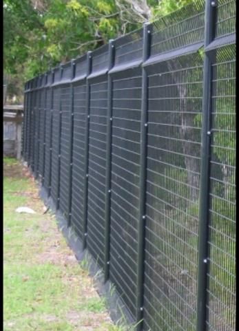
Section 2 – General Requirements for Installation
2.1 Requirements for Pre Treatment and Coating
2.1.1 Cleaning and Chemical Pre-Treatment
The application of cleaning and chemical pre-treatment is required for all fencing panels, posts
and gates, prior to application of the specified coating system, as per the following:
New zinc surfaces are to be examined for flux residues, light roll forming oils and foreign
matter, all of which are to be removed prior to pre-treatment for powder coating. All sharp
edges and uneven protrusions are to be removed.
Surfaces that show white storage stain (white rust) or other corrosion products, must be
cleaned, degreased and pre-treated for optimal performance, as ‘white rust’ can lead to
adhesion problems or out-gassing of the powder coating. Silicone based anti-spatters are not
to be used as they may lead to de-wetting of the powder.
Pre-treatment is to be carried out in accordance with Classification D (High Marine/Industrial)
as per AS 4506.
A summary of pre-treatment and coating thickness requirements as per AS 4506 is below:
Atmospheric Substrate Examples of Minimum Required Test
Classification appropriate pre- coating
treatment thickness,
μm
High Marine- Zinc, Zinc alloys, Zinc phosphate, 60 Adhesion
Industrial Steel (zinc or appropriate Cure
coated) primer system, Thickness
or chrome Neutral salt
chromate spray
or chrome Humidity
phoshate Permiability
Durability
Holiday
Powder application must occur within 24 hours of substrate pre-treatment.
Pre-treatment systems are to be maintained and tested in accordance with the pre-
treatment supplier’s recommendations.
2.1.2 Minimum Coating Requirements
The standard coating for DoE Security Fencing is a hot dip galvanised zinc coating,
appropriate for Corrosion Category C3 (coastal and/or industrial land, with a mild steel
corrosion rate 25 to 50 μm/y), as per AS 4312. A coating mass of ZB135/135(Z275) as per AS
4792 is required as a minimum:
A summary of coating mass of ZB135/135 (Z275) as specified in AS4792 is below:
Local coating Average coating mass, g/m2, min. Strip Coating
Coating Class
mass g/m2, min. External Internal Class
ZB135/135 110 135 135 Z275
102.1.3 Coating Required in Corrosive Environments
Depending of the location of the project, coating appropriate for Corrosion Category C4 (sea
shore, with a mild steel corrosion rate 50 to 80 μm/y) will be requested on an as required
basis. In these cases, the required coating is one of the following:
o A coating type of zinc, aluminium and magnesium (Type ZM) with a coating mass of
ZM275 as specified in AS1397, or
o Batch Hot Dip galvanised (after fabrication) as per AS4680.
A summary of Type ZM with a coating mass of ZM275 as specified in AS 1397, is below:
Minimum Coating mass, g/m2
Coating class Total both surfaces One surface
Triple spot Single spot Single spot
ZM275 275 250 110
A summary of Hot Dip Galvanised zinc coating (after fabrication) as per AS 4680, is below:
Local Coating Average Coating Average Coating mass
Article Thickness
Thickness Minimum Thickness Minimum Minimum
mm μm μm g/m2
≤ 1.5 35 45 320
>1.5 ≤ 3 45 55 390
>3 ≤ 6 55 70 500
>6 70 85 600
2
NOTE: 1 g/m coating mass = 0.14 μm coating thickness
2.1.4 Paint Coating
An epoxy primer of 50-60 μm must be applied to the pre-treated substrate in accordance
with AS 4506 (a 'green cure' is recommended when applying the primer, whereby the
primer is half cured before applying the topcoat).
The topcoat shall consist of a polyester powder coating, black in colour, and in a gloss finish,
applied in accordance with AS 4506 to a minimum of 80 μm, with a total coating thickness
of 130-140 μm.
For corrosive environments, a Class 1 abrasive ‘whip’ blast is to be applied before
the epoxy primer;
The polyester powder coating topcoat must meet or exceed durability, UV stability, and
colourfastness requirements of AS 4506.
The powder must be fully cured as per the powder manufacturer’s specification.
112.2 Clearance and Welding
The contractor is to allow one (1) metre around objects including those identified in Sections
1.5.2 and 1.5.5, however if this is not possible, the panels where services or foliage are
within one (1) metre of the fence line are to be fitted with powder coated perforated steel
mesh.
If any onsite welding is required, it is to be pre-approved by Project Coordinator, and
carried out in accordance with AS/NZS 1554:2014, Structural Steel Welding. Repairs to cut
or damaged powder coated material are to be made using an appropriate anti-corrosion
treatment and coating system that provides the same protection and appearance as the
finished product.
2.3 General Requirements for Panels
The contractor must ensure that full panels are installed on both sides of all gates
wherever practical.
All panels are to be fitted with a maximum ground clearance of 150mm.
Where ground clearance exceeds 150mm, the panels are to be stepped or raked to
achieve the foregoing level of clearance.
Stepped panels must be a minimum width of 1200mm.
After stepping or raking, in-fills are to be fitted and rigidly fixed beneath panels where the
ground clearance still exceeds 150mm.
Barbed wire must not be used as an in-fill underneath panels.
2.4 General Requirements for Gates
The contractor is to allow for the following types and sizes of gates:
o Hinged single gates 1 – 3 metres
o Hinged double gates 2.4 – 7 metres
o Sliding gates As required
o Counter-lever gates As required
Gates are to be manufactured as per the relevant requirements for that particular type of
Security Fencing as detailed in Sections 3, 4 and 5.
All hinged gate/s are to be constructed and installed so as to enable the gate/s to be
locked in the fully open and closed position. Gates are to open and fold back 180
degrees where ground contours allow.
Receiving latches are to be fitted to enable gate/s to be secured with heavy duty
padlocks in the open and closed position.
Galvanised ground sleeves, for the security of drop bolts with the gates in the open and
closed position, are to be installed in concrete so as not to present a trip hazard. Ground
domes must be high enough to inhibit dirt/water ingress and painted yellow to indicate a
possible hazard.
All bolts used for panel and gate hinge fixings must be anti-tamper bolts to prevent the
removal of nuts.
Speed humps must be installed under vehicular gates where the ground clearance exceeds
150mm. Installation of speed humps is to be in accordance with AS 1742:2014 Manual of
Uniform Control Traffic Devices.
The width of all gates is to be in accordance with the provided scope of works for
each project.
122.5 General Requirements for Vehicle Gates
Vehicle access gates must be recessed within the property boundary, where identified as
required for safety, to enable vehicles to stop off road to allow opening and closing of the
gate.
Where a reasonable concern for traffic safety exists, and the Project Coordinator has
given pre-approval, returns are to be splayed to maximise sighting of passing vehicles
and pedestrians.
2.6 General Requirements for Posts and Post Holes
Fence posts, including corner and intermediate posts, are to be installed as set out in
the relevant sections for the respective fence type as specified below.
A post hole (also referred to as a dig) is a machine-drilled or hand dug hole in soil, rock
or other than rock material. All post holes are to be installed as set out in the sections
for the respective fence type:
o Section 3 for Type 1 Security Fencing;
o Section 4 for Type 2 Security Fencing;
o Section 5 for Type 3 Security Fencing.
2.7 General Requirements for Gate Posts
Gate posts are to be set as specified in the relevant Section for each fence type. The above
ground concrete finish is to be domed with a steel trowel finish to eliminate water lying at
base of posts.
Doming of concrete at base of posts must be performed at the time of the concrete pour.
2.8 General Requirements for Padlocks
The contractor is to supply all heavy-duty padlocks (ABUS 83/50 or equivalent) to allow all
gates to be locked. Padlocks are to be keyed to the school registered master key system.
This should be confirmed with the Project Coordinator before locks are installed.
2.9 Site Storage and Protection
Unless alternative arrangements are approved by the Project Coordinator before
commencement of the project, the contractor is to store all goods, materials and equipment
(including any shed or portable toilet), on site within the school boundary in a manner that
will avoid hazards and/or interruptions to school operations, and will not affect
neighbouring properties.
Goods, materials and equipment is to be stored within a secure construction safety fence
(ATF type or similar). Construction fencing used to store equipment is to be a minimum
height of 2100mm.
Safety fencing is to be provided to all work areas including areas where existing fencing is
removed until new fencing is installed. The removal of existing fences should be limited to
areas that can be protected. The type of safety fencing required and the timing of
installation of the safety fencing are to be determined in accordance with the Construction
Safety Plan as described in Workplace Health & Safety procedures. Non rigid
bunting style barrier is not acceptable.
13Site Storage and Protection cont.
The excavation of post holes is to be limited to areas that can be backfilled within the day.
Control measures are be provided to protect the site in accordance with the construction
safety plan as described in Workplace Health & Safety procedures. Trip and subsidence
hazards are to be avoided.
The type of protection required and the timing of the protection works is to be
determined in accordance with normal safety procedures exercised on a designated
construction site.
2.10 General Requirements for Returns
In places where a Security Fence is to adjoin with another type of fence on a private
property (for example a timber or brick fence) which faces a public space such as the
road or footpath, a step point can be created by the private fence. In these cases, the
security fence is to proceed along the front street line of the school to the adjoining
property, and then a return is to be provided along the adjoining property boundary to
provide adequate security for the school.
Returns are also required where the Security Fence is to adjoin to a pre-existing internal
fence in the school grounds.
The relevant Scope of Works, provided for each project, will include any required
provisions for this.
2.11 General Requirements for Block Walls/Celebrated Entryways
Where block walls are included as part of a project scope of works for a celebrated
entryway, the wall height should be 100mm above the total height of the fence line. Any
alterations to existing block walls, or security features required to be affixed to the top of
block walls, will be specified by the Project Coordinator.
The contractor is to redirect the fence as required to allow at least one (1) metre of
clearance around any existing block walls which will create step points.
Any block walls or retaining walls built as part of the project must have relevant Council
approvals, be assessed and certified by a qualified engineer, and comply with the
requirements of AS 3700-2001.
2.11 Electricity and Water
The Contractor must arrange with the Project Co-ordinator at the time of initial
consultation as to the availability of electricity and water if required. Reasonable access to
electricity and water will be provided by the school Principal.
2.12 Key Safe/Garage
Where specified in the project scope of works, a solid metal housing key safe, suitable for
holding padlock keys, is to be affixed to a post of the fence at a location nominated by the
Project Coordinator.
Key safes are to be constructed from zinc die-cast or equivalent, and have a 10 digit code
panel with a plastic weather cover.
Additional key safes will be requested on an as required basis.
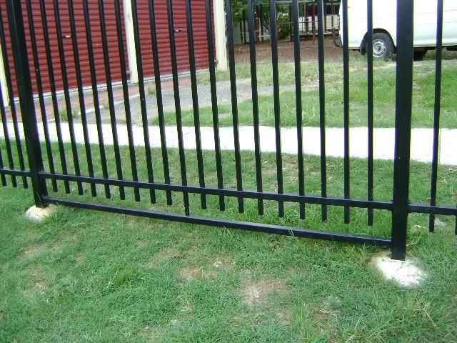
14Section 3 – Type 1 Security Fencing
Type 1 Security Fencing is constructed from panels comprised of black spear-top steel pickets and
rails, manufactured of galvanised steel tube, used predominantly for areas where the boundary line
is accessible from a public space such as street frontage or parkland.
Picture 3.1: A standard Type 1 Security Fence
3.1 Type 1 Security Fencing - Summary
Manufacture Steel pickets and rails, manufactured from galvanised steel tubing, in accordance
with AS 1450 and AS 1397 to a steel Grade of C250 (Summary of C250 below)
Height A minimum standard of 2100mm (heights above this level will be requested on an
as required basis)
Panel Length 2400mm minimum and 2500mm maximum
Number of Two (2)
Rails
Rail 40mm x 40mm x 2.0mm thickness
Measurements
Top Rail 200mm - 270mm from the top of pickets
Position
Rail Centres 1690mm – 1770mm (dependant on height of picket above rail)
Pickets 25mm x 25mm x 1.6mm in thickness x 2100mm in length, punched through
40mm square x 2.0mm rails, and welded on alternative sides of the top and
bottom of both rails with silicon bronze wire
Picket Spacing A standard of 125mm between picket centres, and 115mm between picket
centres for preparatory (Prep) area fencing (115mm picket gaps may also be
requested on an as required basis)
Picket Tops Cut and pressed (crimped) to form a spear point top. Spear tops are to be made
from the same piece of steel tubing as the picket and not attached after
manufacture.
Welding Welded on alternative sides of the top and bottom of both rails, with silicon
bronze wire (i.e. four welds per picket), as per diagrams 3.1 and 3.2 below.
Ground Raised off of the ground, with a 150mm maximum clearance
Clearance
Coating Fully powder coated to meet the requirements as detailed in Section 2.1: Pre-
Treatment and Coating
15A summary of Steel Grade C250 chemical composition, as per AS 1450, is below:
Chemical composition, percent maximum
Grade Type of
Carbon
Designation Analysis C Si Mn P S
equivalent
Cast 0.25 0.40 - 0.040 0.040 0.44
C250
Product 0.29 0.45 - 0.050 0.050 -
3.1.1 Other Information
Vertical pickets are to be welded on alternative sides of the top and bottom of both rails,
with silicon bronze wire (i.e. four welds per picket), as per the diagrams below:
Picture 3.2: Picket Welding 2D view Picture 3.3: Picket Welding 3D view
All welds to be fully rust-proofed and finished to match the fence colour. Finished panels
must be fully powder coated to meet the requirements as detailed in Section 2.1: Pre-
Treatment and Coating.
Where the ground clearance exceeds 150mm, the panels are to be stepped or raked to
achieve the foregoing level of clearance (If panels are to be raked, this will be specified in
the relevant Scope of Works for each project).
Stepped panels must be a minimum length of 1200mm, unless requested in the Scope of
Works for special circumstances. After stepping or raking, in-fills are to be fitted rigidly
beneath panels where the ground clearance still exceeds 150mm. Where in-fills are to
be installed at designated waterways, and the installation will significantly obstruct the
natural flow of water, alternative options are to be sought in consultation with the
Project Coordinator.
3.1.2 Panel Fittings
Panel rails are to be fixed to posts with shrouds. Shrouds are to be equipped with four (4)
holes. Shrouds are to be approved by Project Co-ordinator.
Each shroud is to be affixed to posts with four (4) colour matching self-drilling anti tamper
class three screws.
The rail is to be fixed to the shroud with one (1) colour matching self-drilling anti tamper
class three screw.
16Panel Fittings cont.
Fixings are to be on the inside of the fence, where possible, unless prevented by bracket
positioning.
Where changes of direction are not 90º, the bracket is to be constructed to suit the angle,
and the sleeve is to be purposely made at the required mitre from matching powder
coated material.
Brackets and sleeves must be powder coated to match finished panels and posts to
meet the requirements detailed in Section 2.1: Pre-Treatment and Coating.
Any signs required on the fence should be affixed directly under the top rail.
3.2 Type 1 Security Fencing - Posts
Manufacture Galvanised steel tubing, in accordance with AS 1163 and AS 1397, to a steel
Grade of C350 (Summary of C350 below)
Measurements 75mm x 75mm x 3mm thickness x 3000mm in length
(Straight line
Posts)
Measurements 100mm x 100mm x 4mm thickness x 3000mm in length
(Corner Posts)
Height A minimum standard of 2100mm above ground (heights above this level will
be requested on an as required basis)
The top of each post must be higher than the top of either of the adjoining
fence panels
Post Cap Matching galvanised steel cap to conform with AS 1450 and AS 1397, secured to
the top of the fence post using a colour matching self-drilling anti tamper class
three screw.
Post Footings 250mm minimum diameter with concrete footings not less than 20Mpa in
strength. Requirements for footing depths are detailed in Section 3.6: Type 1
Security Fencing Post Footings
Above ground concrete finishes are to be domed with a steel trowel finish,
to eliminate water lying at the base of posts. Doming of concrete at base of
posts must be performed at the time of the original concrete pour
Post Spacing 2400mm minimum, 2500mm maximum
Coating Fully powder coated to meet the requirements as detailed in Section 2.1: Pre-
Treatment and Coating
A summary of Steel Grade C350 chemical composition as per AS 1450 is below:
Chemical composition, percent maximum
Grade Type of
Carbon
Designation Analysis C Si Mn P S
equivalent
Cast 0.22 0.50 1.60 0.040 0.040 0.49
C350
Product 0.26 0.55 1.70 0.050 0.050 -
173.3 Type 1 Security Fencing – Gates (Hinged)
Manufacture Steel pickets and rails, manufactured from galvanised steel tubing, in
accordance with AS 1450 and AS 1397 to a steel Grade of C250
Sizes As outlined in Section 2.3: General Requirements for Gates.
Measurements 50mm x 50mm x 3mm thickness square box section vertical stiles
50mm x 50mm x 3mm thickness square box section horizontal rails
25mm x 25mm x 1.6mm thickness vertical pickets to match panels
Height A minimum standard of 2100mm (heights above this level will be requested
on an as required basis)
Number of Rails Three (3) total
Twin bottom 50mm square box section rails are to be fitted to bottom
of the gate to provide reinforcing.
Rails 50mm x 50mm x 3mm thickness square box section horizontal rails
Measurements
Top Rail Position 200mm - 270mm from the top of pickets
Rail Centres 1690mm – 1700mm (dependant on height of picket above rail) from
top to middle rail
The gap between the two bottom parallel rails is not to exceed 100mm
Pickets 25mm x 25mm x 1.6mm in thickness x 2100mm in length, punched
through 50mm square x 3mm rails, and welded on alternative sides of the
top and middle rails, and also either side of the picket on the bottom rail,
with silicon bronze wire
Picket Spacing A standard of 125mm between picket centres, and 115mm between picket
centres for preparatory (Prep) area fencing (115mm picket gaps may also
be requested on an as required basis)
Picket Tops Cut and pressed (crimped) to form a spear point top. Spear tops are to be
made from the same piece of steel tubing as the picket and not attached
after manufacture.
Hinges Hinges considered under industry norms as suitable for the type of fence
and gate being installed, and are to be approved by the Project
Coordinator.
Welding Vertical pickets are to be punched through the top and middle rails,
and welded on alternative sides of the top and bottom of the top and
middle rails with silicon bronze wire (as per diagrams 3.1 and 3.2)
Pickets are not required to be punched through the bottom rail but
are to meet flush with the rail and welded either side of the picket.
Each picket shall have a total of six welds
Ground Raised off of the ground, with a 150mm maximum clearance
Clearance
Coating Fully powder coated to meet the requirements as detailed in Section 2.1:
Pre-Treatment and Coating
Fittings Requirements for slide bolts, flag bolt lugs and lock boxes are detailed
below in Section 3.3.2: Gate Fittings
183.3.1 Other Information
All gates are to be constructed to enable the gates to be locked in the fully open and/or
closed position with padlocks (Project Coordinator to confirm required lock size and
style).
Ground sleeves (‘Cow-bell’ style brackets) are to be installed for the security of drop bolts
with the gates in the open and closed position, to eliminate any tripping hazards.
All gates are to be fitted with 20mm slide bolts and Broadhurst lock boxes and padlocks to
each securing point. These locks and bolts are to be supplied by the contractor. Abus 83/50
series padlocks or equivalent are to be used. Shackle-less padlocks are to be fitted to all slide
bolts. The slide bolt should be fitted internally, immediately above the parallel centre.
There is to be no diagonal bracing on gates.
3.3.2 Gate Fittings
Double gates are to have internal flag bolts or similar locking mechanism no less than
1200mm in length from the bottom of each individual gate. Steel tags are to be welded to
the gate to accommodate the flag bolt when in the open and closed position through
passing a padlock through the flag.
Flag bolts or similar locking mechanisms are to have a 20mm diameter steel bar.
Flag bolt lugs are to be elongated in height and to be bolted to the closing post. Locking
lugs are to be welded to the frame to accommodate the flag bolt in the closed position.
Perforated metal is to be affixed against the gate stile. This must be designed specifically to
stop access to the locking mechanism from outside the gate. In cases where dual access is
required a portion of the perforated metal will be cut in proximity to the locking device to
allow hand access (i.e. access through double gates for emergency service personnel). The
cut edges of perforated panels are to be finished to remove any sharp edges.
193.4 Type 1 Security Fencing - Gate Posts
Manufacture Galvanised steel tubing, in accordance with AS 1163 and AS 1397, to a steel
Grade of C350
Measurements 100mm x 100mm x 4mm thickness x 3000mm in length
(Gates up to five
(5) metres)
Measurements 150mm x 150mm x 5mm thickness x 3000mm in length
(Gates over five
(5) metres)
Height A minimum standard of 2100mm above ground (heights above this level
will be requested on an as required basis)
Post Cap Matching galvanised steel cap to conform with AS 1450 and AS 1397,
secured to the top of the fence post using a colour matching self-drilling
anti tamper class three screw.
Post Footings 450mm minimum diameter with concrete footings not less than 20Mpa
in strength. Requirements for the depth of post footings are detailed in
Section 3.6: Type 1 Security Fencing Post Footings
For pedestrian use gates, a concrete plinth 400mm wide x 150mm
depth is to be installed between gate posts
For vehicle use gates, a concrete plinth 400mm wide x 300mm depth is
to be installed between gate posts
Above ground concrete finishes are to be domed with a steel trowel
finish, to eliminate water lying at the base of posts.
Doming of concrete at base of posts must be performed at the time of
the original concrete pour
Coating Fully powder coated to meet the requirements as detailed in Section 2.1:
Pre-Treatment and Coating
203.5 Type 1 Security Fencing – Gates (Sliding)
Manufacture Steel pickets and rails, manufactured from galvanised steel tubing, in
accordance with AS 1450 and AS 1397 to a steel Grade of C250
Sizes As outlined in Section 2.3: General Requirements for Gates.
Sliding gate panels are to be a minimum of 600mm longer than
the gate opening
Measurements 50mm x 50mm x 3mm thickness square box section vertical stiles
50mm x 50mm x 3mm thickness square box section horizontal rails
100mm x 50mm x 3mm thickness bottom rail
25mm x 25mm x 1.6mm thickness vertical pickets to match panels
Height A minimum standard of 2100mm (heights above this level will be requested
on an as required basis)
Number of Rails Three (3) total
Top and middle rail are to be 50mm square x 3mm thickness box
section horizontal rails
100mm x 50mm x 3mm thickness box section rail is to be fitted to the
bottom of the gate to provide reinforcing
Top Rail Position 200mm - 270mm from the top of pickets
Rail Centres 1690mm – 1700mm (dependant on height of picket above rail) from
top to middle rail
The gap between the two bottom parallel rails is not to exceed 100mm
Pickets 25mm x 25mm x 1.6mm in thickness x 2100mm in length, punched
through 50mm square x 3mm rails, and welded on alternative sides of the
top and middle rails, and also either side of the picket on the bottom rail,
with silicon bronze wire
Picket Spacing A standard of 125mm between picket centres, and 115mm between picket
centres for preparatory (Prep) area fencing (115mm picket gaps may also
be requested on an as required basis)
Picket Tops Cut and pressed (crimped) to form a spear point top. Spear tops are to be
made from the same piece of steel tubing as the picket and not attached
after manufacture.
Wheels Double bearing bottom wheels with upper nylon guide rollers.
Track Galvanised steel track comprising 90mm x 6mm plate with 20mm solid
rod welded on centre line, with two (2) 12mm holes 50mm in from
edges at 500mm centres
Track to be fixed to concrete slab with 10mm x 50mm galvanised dyna
bolts
Concrete slab under track to be length of gate + sliding range x 400mm
x 300mm deep
Catcher Bracket/ 100mm x 100mm x 5mm post with steel guide to accommodate
Stopping Post impact of gate when in the open position
Post is to be fixed in position with four (4) heavy duty galvanised dyna
bolts which are to be anchored into a concrete footing
Where necessary, the upright is to be braced to combat movement
caused through constant impact
21Type 1 Security Fencing – Gates (Sliding) cont.
Coating Fully powder coated to meet the requirements as detailed in Section 2.1: Pre-
Treatment and Coating
Fittings Requirements for slide bolts, flag bolt lugs and lock boxes are detailed below
in Section 3.5.1: Other Information
3.5.1 Other Information
Vertical pickets are to be punched through the top and middle rails, and welded on
alternative sides of the top and bottom of the top and middle rails with silicon bronze wire
(as per diagrams 3.1 and 3.2)
Pickets are not required to be punched through the bottom rail but are to meet flush
with the rail and welded either side of the picket. Each picket shall have a total of six
welds
A 40mm x 10mm x 50mm lug is to be welded with a 20mm hole to secure the gate in the
open and closed position.
There must be a slot in the catcher bracket to receive the lug welded on the gate.
The lug is to be constructed to accommodate a padlock (Project Coordinator to confirm
required size and style of locks).
Sliding gates are to be guided through a minimum of two (2) ‘U frames’ comprising 100mm x
100mm x 4mm posts.
Posts are to be secured in place with a 5mm (minimum) steel bracing plate, coated to meet
the requirements as detailed in Section 2.1: Pre-Treatment and Coating.
There is to be no diagonal bracing on gates.
223.6 Type 1 Security Fencing – Post Footings
Requirements for the depth of Type 1 Security Fencing post footings are dependent on:
o The Wind Region and Terrain Categories of the project location, as per AS 1170.2-
2011, Structural Design Actions – Wind actions;
o The Site Classification of the soil type of the project location as per AS2870-2011,
Residential Slabs and Footings.
Requirements for post footing depths are outlined in the table as part of the diagram below:
Picture 3.4: Post footing requirements for Type 1 Security Fencing
23Section 4 – Type 2 Security Fencing
Type 2 Security Fencing is constructed from chain-link fabric, used predominantly for (but not
exclusive to) areas where the school shares a boundary line with private property.
Picture 4.1: A standard Type 2 Security Fence
4.1 Type 2 Security Fencing – Summary
Manufacture Galvanised steel pipe, in accordance with AS 1725.1 and AS 1163 to a steel
(Posts and Rails) Grade of C250
Manufacture Steel wire manufactured from hot-rolled carbon steel rods of chemical
(Chain Link) compositions in accordance with AS 1442, protected against corrosion by
application of a metallic coating during manufacture in accordance with AS
2423
Height A minimum standard of 2100mm (heights above this level will be requested on
an as required basis)
Panel Length 2400mm minimum and 2500mm maximum
Chain Link Fabric Galvanised steel wire 3.15mm diameter, 50mm pitch in accordance with
Measurements AS 1725 and AS 2423
Black PVC coated 4.15mm diameter, 50mm pitch may be requested on an
as required basis (PVC is to be applied over galvanised steel wire)
Support Cables 4mm diameter helicoil in the same coating quality as the chain link fabric
Tie Wires and 2mm diameter in the same coating quality as the chain link fabric
Clips Ties wires are required for intermediate posts every 4 links at a minimum
Every second chain link diamond on top rail and every second chain link
diamond on bottom rail are to be individually secured using double
wrapped tie wire. Continuous lacing is not acceptable
At the end posts and gateposts every chain link diamond is to be
individually secured using double wrapped tie wire to end posts, internal
corner posts and gateposts
Chain link fabric is to be clipped to the helicoil wire with no less than 2x
clips per panel
Top Rail Chain link fabric is to be finished with barbed top selvedge and knuckled
bottom selvedge
The barb is to be above the top rail
24Type 2 Security Fencing – Summary cont.
Ground The space between the bottom selvedge of the chain link fabric and the
Clearance ground is to clear the ground surface as ground contours allow, and be small
enough to sufficiently maintain security.
Coating The galvanised (zinc) coating on the steel pipes is to comply with AS/NZ
4792
Where powder coating is requested for posts, coating is to be applied as
specified in Section 2.1: Pre-Treatment and Coating
A summary of Steel Grade C250 chemical composition, as per AS 1450, is below:
Chemical composition, percent maximum
Grade Type of Carbon
Designation Analysis C Si Mn P S equivalent
(See note)
Cast 0.25 0.40 - 0.040 0.040 0.44
C250
Product 0.29 0.45 - 0.050 0.050 -
4.1.1 Other Information
All fittings are to be colour matched as per the request for each project.
All items welded or cut must be primed, followed by galvanising or black paint as required
for the project.
All fittings, including nuts and bolts, are to be cut to stop removal.
Chain link fabric is to be placed on the outside of posts and strained taut and secured to
each support cable, all rails, all posts and bracing rails with tie wires, except at the end posts
and gateposts
Every second chain link diamond on top rail and every second chain link diamond on
bottom rail are to be individually secured using double wrapped tie wire. Continuous lacing
is not acceptable
Chain link fabric is to be placed on the outside of posts and strained taut, secured to each
support cable, all rails, all posts and bracing rails with tie wires, except at end posts and
gateposts
At the end posts and gateposts, the every chain link diamond is to be individually secured
using double wrapped tie wire to end posts, internal corner posts and gateposts
If bracing rails, bracing stays and back stays are required they are to be provided
without joints, and are to be 32mm extra light nominal bore
All rails are to be securely connected to posts with an industry approved galvanised steel
clamp.
254.2 Type 2 Security Fencing – Posts
Manufacture Galvanised steel pipe, in accordance with AS 1725.1 and AS 1163 to a steel
Grade of C250
Measurements Corner posts are to be galvanised steel pipe DN50
Intermediate posts are to be galvanised steel pipe DN40
Single gate posts are to be galvanised steel pipe DN50
Double gate posts are to be galvanised steel pipe DN80
Top rails are to be galvanised steel pipe DN32
Bottom rails are to be galvanised steel pipe DN32
Height A minimum standard of 2100mm above ground (heights above this level
will be requested on an as required basis)
Footings 250mm minimum diameter not less than 20Mpa in strength.
(Intermediate Requirements for the depth of post footing are detailed in Section 4.4:
Posts) Type 2 Security Fencing Post Footings
Above ground concrete finish is to be domed with steel trowel finish to
eliminate water lying at base of posts and is to be completed at time of
original concrete pour
Footings (Corner 250mm minimum diameter x 750mm minimum depth with not less
Posts) than 20Mpa in strength
Above ground concrete finish is to be domed with steel trowel finish to
eliminate water lying at base of posts and is to be completed at time of
original concrete pour
4.2.1 Other Information
Ends of the support cable wire are to be firmly secured to all terminal posts.
If a top rail is specified as not to be used, then the top support cable is to be
positioned one half-diamond below the top selvedge of the chain link fabric.
The bottom support cable is to be positioned not more than one diamond above the
bottom selvedge of the chain link fabric.
Knotted joins in cable wire are not permitted.
264.3 Type 2 Security Fencing - Gates
Manufacture Galvanised steel pipe, manufactured in accordance with AS 1725.1 and AS
(Posts and Rails) 1163 to a steel Grade of C250
Manufacture Steel wire manufactured from hot-rolled carbon steel rods of chemical
(Chain Link) compositions in accordance with AS 1442, protected against corrosion by a
metallic coating applied during manufacture in accordance with AS 2423
Sizes As outlined in Section 2.3: General Requirements for Gates.
Height A minimum standard of 2100mm (heights above this level will be
requested on an as required basis)
The height of the gate is to match the height of the fence (allowing for
sufficient minimum ground clearances)
Frame Gate outer frame to be constructed of DN25 and inner frame of DN20.
Design to be in accordance with AS 1725.1.
Posts Corner posts are to be galvanised steel pipe DN50
Intermediate posts are to be galvanised steel pipe DN40
Single gate posts are to be galvanised steel pipe DN50
Double gate posts are to be galvanised steel pipe DN80
Top rails are to be galvanised steel pipe DN32
Bottom rails are to be galvanised steel pipe DN32
Chain Link Fabric Galvanised steel wire 3.15mm diameter, 50mm pitch in accordance
Measurements with AS 1725 and AS 2423
Black PVC coated 4.15mm diameter, 50mm pitch may be requested on
an as required basis (PVC is to be applied over galvanised steel wire)
Chain link fabric applied to gates is to match the fabric on the fence
Support Cables 4mm diameter helicoil in the same coating quality as the chain link fabric
Tie Wires and 2mm diameter in the same coating quality as chain link fabric
Clips Ties wires required for intermediate posts at minimum every 4 links
Every second chain link diamond on top rail and every second chain
link diamond on bottom rail are to be individually secured using double
wrapped tie wire. Continuous lacing is not acceptable
At the end posts and gateposts every chain link diamond is to be
individually secured using double wrapped tie wire to end posts,
internal corner posts and gateposts
Chain link fabric is to be clipped to the helicoil wire with no less than 2x
clips per panel
Top Rail Chain link fabric is to be finished with barbed top selvedge and
knuckled bottom selvedge
The barb is to be above the top rail
Ground The space between the bottom selvedge of the chain link fabric and the
Clearance ground is to clear the ground surface as ground contours allow, and be
small enough to sufficiently maintain security.
Drop Bolt A flag drop bolt or similar locking mechanism made from a 16mm
diameter, galvanised steel pin, is to be installed no less than 1200mm in
length from the bottom of each individual gate
Coating Where powder coating is requested for posts, coating is to be applied
as specified in Section Section 2.1: Pre-Treatment and Coating
274.3.1 Other Information
The chain link fabric is to be tied individually to the gate frame on every chain link diamond
to gate frame and along the internal bracing.
All joints are to be fully welded, staggered welding is not acceptable.
Two coats of approved zinc-rich paint are to be applied to all galvanised surfaces damaged
by welding.
Brackets are to be fitted to each double-leaf gate for the provision of locking the gates.
Galvanised ‘cowbell’ brackets are to be provided at ground level, to hold the gates in both
the open and closed position. The devices should be installed as to not present a trip hazard.
Doming of concrete is to be sufficiently high enough to prohibit the ingress of dirt and is to
be painted yellow to indicate possible trip hazard.
Locking lugs are to be welded to the frame to accommodate the flag bolt being secured in
the ‘cowbell bracket’ in the closed position.
Flag bolts or similar locking mechanisms are to have a 20mm diameter steel bar.
Gate hinges are to be heavy duty, and secured to prohibit removal of the gate.
Gates are to open 180 degrees and lock back against fence line where ground contours
allow.
4.3.2 Base plates
Base plates can be installed where suitable concrete pavement or similar surfaces are
available.
When a base plate is installed, the base plates are to be fixed with four (4) heavy duty
galvanised dyna bolts to the concrete.
Posts are to be fully secured with the bolt nuts welded or burred to prevent
removal.
284.4 Type 2 Security Fencing – Post Footings
Requirements for the depth of Type 2 Security Fencing post footings are dependent on:
o The Wind Region and Terrain Categories of the project location, as per AS 1170.2-
2011, Structural Design Actions – Wind actions;
o The Site Classification of the soil type of the project location as per AS2870-2011,
Residential Slabs and Footings.
Requirements for post footing depths are outlined in the table as part of the diagram below:
Picture 4.2: Post footing requirements for Type 2 Security Fencing
29Section 5 – Type 3 Security Fencing
Type 3 Security Fencing Fencing constructed from welded wire mesh, used predominantly (but not
exclusive to) for areas not visible to the general public, for example near creeks or in rural areas,
including sporting and agricultural areas.
Picture 5.1: A standard Type 3 Security Fence
5.1 Type 3 Security Fencing - Summary
Manufacture Continuous welded galvanised steel wire mesh panels, with two (2) horizontal
presses, foiled base and spiked tops, in accordance with AS 2423
Mesh 5mm diameter steel wire, with 50mm horizontal spacing x 75mm vertical spacing,
welded at each crossover point
Height A minimum standard of 2100mm (heights above this level will be requested on an
as required basis)
Length 2400mm
Smaller panel lengths may be requested where ground clearance exceeds
acceptable levels due to ground contours
Fittings All panels are to be fitted with U clips, total number to be determined by total
height of panel/s and predrilled holes in posts
Ground Clearing the ground surface, but small enough to sufficiently maintain security
Clearance
Coating Panels are to be galvanised after manufacture to meet the requirements as
detailed in Section 2.1: Pre-Treatment and Coating
305.2 Type 3 Security Fencing -Posts
Manufacture Galvanised steel Rectangular hollow section (RHS) posts, in accordance with
AS2423
Measurements 50mm nominal bore /60.3mm outside diameter, with a wall thickness of
(For up to 3.6mm
2400mm height)
Measurements 80mm nominal bore /88.9mm outside diameter, with a wall thickness of 4mm
(For over
2400mm height)
Height A minimum standard of 2100mm above ground (heights above this level will
be requested on an as required basis)
Post Cap Matching galvanised steel cap to conform with AS 1450 and AS 1397, secured
to the top of the fence post using a colour matching self-drilling anti tamper
class three screw.
Footings 250mm minimum diameter not less than 20Mpa in strength. Requirements for
the depth of footings are detailed in Section 5.4: Type 3 Security Fence Post
Footings
Fittings Galvanised U clips must be fastened to posts at each predrilled hole
Hexagonal head galvanised bolts and nuts are to be:
o M8 x 90mm for 50mm NB posts
o M8 x 100mm for 80mm NB posts
Coating Posts are to be galvanised after manufacture in accordance with AS 4792 and
to meet the requirements as detailed in Section 2.1: Pre-Treatment and
Coating
Each post can be drilled with 11-14 x 10mm holes, dependent upon the total height of
combined panels, and must include a hole to enable stepping of panels where necessary
315.3 Type 3 Security Fencing - Gates
Manufacture Continuous welded galvanised steel wire mesh panels, with two (2) horizontal
presses, foiled base and spiked tops, in accordance with AS 2423
Frame 32mm nominal bore galvanised steel pipe frame and internal bracing. Spike
top is to protrude 50mm above the top of the gate frame, level with top of
the gate stile
Mesh 5mm diameter steel wire, with 50mm horizontal spacing x 75mm vertical
spacing, welded at each crossover point
Sizes As outlined in Section 2.3: General Requirements for Gates
Height A minimum standard of 2100mm (heights above this level will be
requested on an as required basis)
The height of the gate is to match the height of the fence (allowing for
sufficient minimum ground clearances) with a spiked top
Posts Galvanised steel PHS posts, 100mm nominal bore/ 114.3mm outside
diameter, with a wall thickness of 4.5mm
Post Cap Matching galvanised steel cap to conform with AS 1450 and AS 1397, secured
to the top of the fence post using a colour matching self-drilling anti tamper
class three screw.
Fittings Hexagonal head galvanised bolts and nuts are to be M8 x 150mm for 100mm
NB posts
Hinges Galvanised steel hinges that are bolted or welded to the posts
Ground The gate is to clear the ground surface, but be as close to the ground as
Clearance possible
Drop Bolts Requirements for drop bolts are described below
Coating Gates are to be galvanised after manufacture in accordance with AS 4792 and
to meet the requirements as detailed in Section 2.1: Pre-Treatment and
Coating
Each leaf is to have a 32mm nominal bore galvanised steel internal stile between the
middle and bottom rails. There is to be a 100mm space with no mesh from the closing stile,
to allow external access to the drop bolt and lock.
Gates must have an internal Broadhurst or similar protected/encased locking mechanism
and a hand hole 1500mm from the bottom of the gate.
The protected/encased locking mechanism is to be fitted with a 20mm diameter steel bar
and two lugs, or one lug of sufficient width, bolted to the closing post to receive the shot
bolt, preventing the gates opening when the drop bolts are not secured.
Weldmesh infill is to remain over hand hole.
Gates are to be equipped with an 850mm lockable drop bolt.
Flag bolts or similar locking mechanisms are to have a 20mm diameter steel bar.
Where it is not possible to engage the drop bolt to the ground level then provision is to be
made for the installation of an 1800mm galvanised steel post, measuring 65mm x 65mm x
2.5mm.
The slide bolt is to be lockable in both the open and closed position.
Gates are to open 180 degrees and lock back against fence line where ground
contours allow.
32You can also read