Ready Solutions for Data Analytics - Big Data as a Service (Ready Solutions for Big Data) Architecture Guide - Dell EMC
←
→
Page content transcription
If your browser does not render page correctly, please read the page content below

Ready Solutions for Data Analytics
Big Data as a Service (Ready Solutions for Big Data)
                Architecture Guide
                    February 2019
                      H17286.1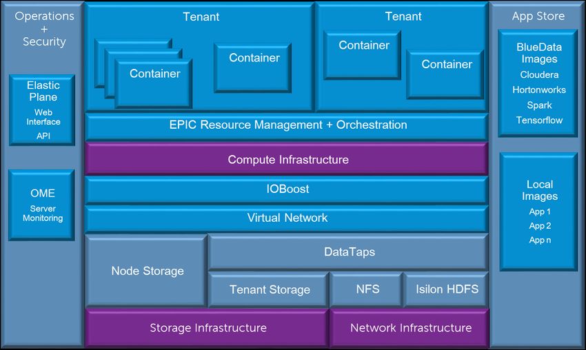
ii | Contents

           Contents
                 List of figures..................................................................................................................... iv

                 List of tables....................................................................................................................... v

                 Trademarks........................................................................................................................ vi
                 Notes, cautions, and warnings......................................................................................... vii

                 Chapter 1: Solution overview..............................................................................................8
                         Overview...............................................................................................................................................9

                 Chapter 2: Solution architecture....................................................................................... 11
                         Architecture overview.........................................................................................................................12
                         Solution components..........................................................................................................................12
                         Deployment architecture.................................................................................................................... 13

                 Chapter 3: Software architecture......................................................................................15
                         Software overview..............................................................................................................................16
                         Elastic Plane cluster management.................................................................................................... 16
                                 App Store................................................................................................................................ 16
                                 App Workbench.......................................................................................................................16
                         Multi-tenancy and role-based security...............................................................................................16
                                 Tenants.................................................................................................................................... 17
                                 Role-based security.................................................................................................................18
                         Resource management......................................................................................................................18
                                 Node flavors............................................................................................................................ 18
                                 Resource allocation.................................................................................................................19
                                 Quotas..................................................................................................................................... 20
                         Storage access and management.....................................................................................................20
                                 DataTaps..................................................................................................................................20
                                 Tenant storage........................................................................................................................ 21
                                 Node storage...........................................................................................................................21

                 Chapter 4: Cluster architecture.........................................................................................22
                         Cluster architecture............................................................................................................................ 23
                         Node roles definitions........................................................................................................................ 24
                         Sizing summary..................................................................................................................................24
                         Rack layout........................................................................................................................................ 25

                 Chapter 5: Hardware architecture.................................................................................... 27
                         Dell EMC PowerEdge rack servers...................................................................................................28
                               Dell EMC PowerEdge R640 server........................................................................................ 28
                               Dell EMC PowerEdge R740xd server.................................................................................... 28
                         Server hardware configurations.........................................................................................................28
                               Administration Node................................................................................................................ 29
                               Gateway Nodes.......................................................................................................................29
                               Worker Nodes - high density.................................................................................................. 30

                Ready Solutions for Data Analytics | Big Data as a Service (Ready Solutions for Big Data) | February 2019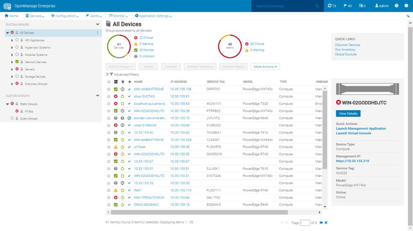
Contents | iii

                     Worker Nodes - GPU accelerated..........................................................................................30

   Chapter 6: Network architecture.......................................................................................32
           Physical network architecture............................................................................................................ 33
           Physical network definitions...............................................................................................................33
           Physical network components........................................................................................................... 33
                 Server node connections........................................................................................................ 34
                 25 GbE pod switches..............................................................................................................35
                 25 GbE Layer 2 cluster aggregation...................................................................................... 36
                 iDRAC management network................................................................................................. 37
                 Network equipment summary - 25 GbE................................................................................. 37
           Logical network architecture.............................................................................................................. 38
           Logical network definitions.................................................................................................................39
           Core network integration....................................................................................................................39

   Chapter 7: Solution monitoring......................................................................................... 40
           Cluster monitoring.............................................................................................................................. 41
           Hardware monitoring..........................................................................................................................41

   Appendix A: References................................................................................................... 42
           About BlueData.................................................................................................................................. 43
           About Cloudera.................................................................................................................................. 43
           About Red Hat................................................................................................................................... 43
           About Dell EMC Customer Solution Centers.................................................................................... 43
           To learn more.....................................................................................................................................44

   Glossary............................................................................................................................45

   Index................................................................................................................................. 54

Ready Solutions for Data Analytics | Big Data as a Service (Ready Solutions for Big Data) | February 2019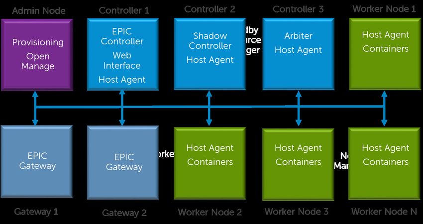
iv | List of figures

            List of figures
                  Figure 1: Solution components........................................................................................ 12

                  Figure 2: Solution deployment architecture..................................................................... 14

                  Figure 3: Solution Cluster architecture............................................................................ 23

                  Figure 4: Solution rack layout.......................................................................................... 26

                  Figure 5: Dell EMC PowerEdge R640 server 10 x 2.5" chassis......................................28

                  Figure 6: Dell EMC PowerEdge R740xd server 3.5” chassis.......................................... 28

                  Figure 7: Physical network architecture...........................................................................33

                  Figure 8: Dell EMC PowerEdge R640 network ports...................................................... 34

                  Figure 9: Dell EMC PowerEdge R740xd network ports.................................................. 34

                  Figure 10: 25 GbE single pod networking equipment..................................................... 36

                  Figure 11: Dell EMC Networking S5048F-ON multiple pod networking equipment......... 37

                  Figure 12: Network fabric architecture.............................................................................38

                  Figure 13: OME health monitoring...................................................................................41

                 Ready Solutions for Data Analytics | Big Data as a Service (Ready Solutions for Big Data) | February 2019
List of tables | v

List of tables
    Table 1: Cluster node roles..............................................................................................23

    Table 2: Recommended cluster size - 25 GbE................................................................24

    Table 3: Alternative cluster sizes - 25 GbE..................................................................... 25

    Table 4: Rack and pod density scenarios........................................................................25

    Table 5: Hardware configurations – Dell EMC PowerEdge R640 Administration
      Node............................................................................................................................. 29

    Table 6: Hardware configurations – Dell EMC PowerEdge R640 Gateway Node............29

    Table 7: Hardware configurations – Dell EMC PowerEdge R740xd Worker Nodes -
      high density.................................................................................................................. 30

    Table 8: Hardware configurations – Dell EMC PowerEdge R740xd Worker Nodes -
      GPU accelerated.......................................................................................................... 30

    Table 9: Solution network definitions............................................................................... 33

    Table 10: Network / Interface Cross Reference...............................................................34

    Table 11: Per rack network equipment - 25 GbE............................................................ 37

    Table 12: Per pod network equipment - 25 GbE............................................................. 37

    Table 13: Per cluster aggregation network switches for multiple pods - 25 GbE............. 38

    Table 14: Per node network cables required – 25 GbE configurations............................38

    Table 15: Solution logical network definitions.................................................................. 39

 Ready Solutions for Data Analytics | Big Data as a Service (Ready Solutions for Big Data) | February 2019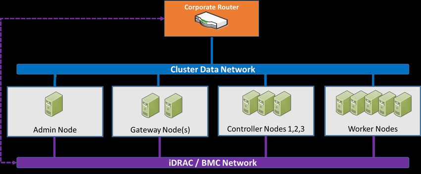
vi | Trademarks

          Trademarks
                  The information in this publication is provided “as is.” Dell Inc. makes no representations or warranties of
                  any kind with respect to the information in this publication, and specifically disclaims implied warranties of
                  merchantability or fitness for a particular purpose.
                  Use, copying, and distribution of any software described in this publication requires an applicable software
                  license.
                  Copyright © 2018-2019 Dell Inc. or its subsidiaries. All rights reserved. Dell, EMC, Dell EMC and other
                  trademarks are trademarks of Dell Inc. or its subsidiaries. Other trademarks may be trademarks of their
                  respective owners.
                  Dell believes the information in this document is accurate as of its publication date. The information is
                  subject to change without notice.

            Ready Solutions for Data Analytics | Big Data as a Service (Ready Solutions for Big Data) | February 2019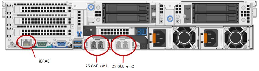
Notes, cautions, and warnings | vii

Notes, cautions, and warnings
           Note: A Note indicates important information that helps you make better use of your system.

           CAUTION: A Caution indicates potential damage to hardware or loss of data if instructions are not
           followed.
           Warning: A Warning indicates a potential for property damage, personal injury, or death.

    This document is for informational purposes only and may contain typographical errors and technical
    inaccuracies. The content is provided as is, without express or implied warranties of any kind.

 Ready Solutions for Data Analytics | Big Data as a Service (Ready Solutions for Big Data) | February 2019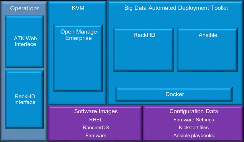
8 | Solution overview

          Chapter

          1
          Solution overview
          Topics:                                  This guide describes the Big Data as a Service solution, a Dell EMC
                                                   Ready Solution for Data Analytics. It covers the solution architecture
          •   Overview                             overall, the software architecture, the design of the nodes and clusters,
                                                   the hardware components and architecture, the network design, and
                                                   the operational monitoring of the solution.

               Ready Solutions for Data Analytics | Big Data as a Service (Ready Solutions for Big Data) | February 2019
Solution overview | 9

Overview
    In today’s highly competitive business climate, organizations require insight into business operations as
    they happen, so they can respond to quickly changing market conditions. So naturally, data analytics, or
    Big Data, is reshaping industries by enabling rapid data-based decision making. Big Data has become an
    essential component of digital transformation across marketing, operations, finance — really all aspects of
    the modern business enterprise.
    Yet, deploying Big Data environments can be very complex and time-consuming. The numerous tasks may
    include:
    •   Acquiring and deploying the compute nodes with storage
    •   Performing network configurations
    •   Installing operating systems
    •   Deploying Hadoop clusters
    •   Installing other analytic applications
    •   Testing and validating
    •   Administering the users
    •   Aecuring all of the elements
    •   Separately monitoring and managing all of the components
    The complexity can also introduce risk, as well as time, particularly when there are multiple requests and
    varying needs coming from different functions and departments within the organization.
    This solution is designed to simplify and accelerate Big Data deployments. Multi-tenant Big Data
    deployments that may have taken months can now be completed within a couple of days. Once the
    platform is deployed, data scientists and analysts can create their own virtual data analytic clusters on-
    demand within minutes — while accessing centralized data and reducing duplication.
    This solution is part of Dell EMC's Ready Solutions for Data Analytics portfolio and includes the following
    elements:
    •   A complete enterprise-grade hardware infrastructure stack from Dell EMC, including scalable and
        high-performance compute, storage, and networking elements.
    •   The BlueData Elastic Private Instant Clusters (EPIC) software, a platform that enables Big Data as
        a Service by deploying a wide range of pre-packaged containerized data analytic applications.
    •   Automated lifecycle management operations and end-to-end infrastructure monitoring with Dell EMC
        OpenManage Enterprise.
    •   An extensive and validated ecosystem of containerized data analytic services, accessible via the
        BlueData App Store.
    •   An available jumpstart services package, including deployment, on-site integration, and initial
        consulting services.
    •   Plus, along with the jumpstart services, the Big Data Automated Deployment Tool Kit (ADTK) from
        Dell EMC is included to ensure rapid, reliable, and risk-free deployments.
    The wide range of capabilities in this solution make this a complete turn-key solution for Big Data as a
    Service that can be deployed quickly and efficiently as a platform, and then in turn offer rapid on-demand
    analytic services to end users with efficient utilization of resources for the organization as a whole.
    The benefits of such a complete Big Data as a Service solution are numerous and allow the organization
    to:
    •   Simplify on-premises deployments with a turnkey BDaaS solution.
    •   Increase business agility by empowering data scientists and analysts to create Big Data clusters in a
        matter of minutes, with just a few mouse clicks.
    •   Minimize the need to move data by independently managing and scaling compute and storage.
    •   Maintain security and control in a multi-tenant environment, integrated with your enterprise security
        model (e.g. LDAP, AD, or Kerberos).

 Ready Solutions for Data Analytics | Big Data as a Service (Ready Solutions for Big Data) | February 2019
10 | Solution overview
• Achieve cost savings of up to 75% compared to traditional deployments by improving utilization,
controlling usage, eliminating cluster sprawl, and minimizing data duplication.
• Deliver faster time-to-insights with pre-integrated images for common data science, analytics,
visualization, and business intelligence tools – including Cloudera Hadoop, Hortonworks Hadoop,
Spark, TensorFlow, Cassandra, Kafka, and others.
Ready Solutions for Data Analytics | Big Data as a Service (Ready Solutions for Big Data) | February 2019Solution architecture | 11
Chapter
2
Solution architecture
Topics: The overall architecture of the solution addresses all aspects of
implementing this solution in production, including the software
• Architecture overview layers, the physical server hardware, the network fabric, scalability,
• Solution components performance, and ongoing management.
• Deployment architecture This chapter summarizes the main aspects of the solution architecture.
Ready Solutions for Data Analytics | Big Data as a Service (Ready Solutions for Big Data) | February 201912 | Solution architecture
Architecture overview
As Big Data deployments expand to meet the needs of multiple organizations and applications, supporting
diverse data analytics workloads and user groups requires increased agility and streamlined operations.
Implementing a Big Data as a Service environment can provide a solution for these needs. A Big Data as a
Service environment has the following key requirements:
• Streamlined operations — Big Data as a Service must provide streamlined operations through
self service with secure multi-tenancy, while simplifying resource management and providing high
availability and performance.
• Compute abstraction layer — Applications and clusters on demand must be supported without
concern for physical compute infrastructure allocation. Resource management must provide capacity
management and scalability. Applications should be templated to hide the details of physical compute
requirements.
• Storage abstraction layer — Local, remote, and shared storage must be supported, including security
and multi-tenant isolation.
• Hardware infrastructure Layer — The hardware infrastructure must provide high performance
compute, network, and storage, with management capabilities. The infrastructure must be scalable and
support independent allocation of compute, network, and storage resources.
The architecture of this solution embodies all the hardware, software, resources, and services needed to
meet these requirements in a production environment. Based on BlueData EPIC, this integrated solution
means that you can be in production within a shorter time than is typically possible with homegrown
solutions.
Solution components
This solution addresses the requirements of Big Data as a Service by integrating multiple hardware and
software components that provide the necessary functions. Figure 1: Solution components on page 12
illustrates the primary functional components in this solution.
Figure 1: Solution components
Ready Solutions for Data Analytics | Big Data as a Service (Ready Solutions for Big Data) | February 2019Solution architecture | 13
• Containers provide the core runtime abstraction for the user applications. These containers provide
isolation between user applications and the rest of the infrastructure. The containers are based on
Docker.
• The Resource management and orchestration Layer is the core operational component in the
system, and is provided by EPIC. This layer is responsible for allocating resources to applications, and
creating and monitoring container instances to execute those applications. In EPIC, container instances
are referred to as virtual nodes. Elastic Plane provides the operational interface to this layer.
• Tenants are an abstraction that provide multi-tenancy capabilities by grouping container instances.
Containers associated with a tenant are isolated from other tenants at the network, compute, and
storage levels.
• The App Store is a repository of application images, allowing fully automated self service deployment.
Images in the App Store are preconfigured and ready to run, including complete cluster support.
Images for Hadoop and other Big Data platforms are provided with the base installation. The application
workbench enables users to quickly add images for any other Big Data application or data processing
platform.
• The Compute infrastructure provides the memory, processor, hardware accelerator and I/O resources
to support container execution. This infrastructure is provided by Dell EMC PowerEdge servers.
• IOBoost is an EPIC component that ensures performance comparable to bare metal in the
containerized environment.
• The Virtual network layer is responsible for dynamically assigning network addresses to container
instances, supporting tenant isolation at the network level, and managing connectivity between
container instances and external networks. This layer is provided as part of EPIC.
• Node storage provides local storage for a container instance while it is running. This storage is
ephemeral, and is removed when a container instance completes.
• DataTaps provide access to remote storage for containers. DataTaps are associated with a tenant,
so multiple applications and containers can share a DataTap while the DataTap is isolated from other
tenants.
• Tenant storage is a DataTap that provides persistent shared storage accessible by all nodes within a
given tenant. The underlying filesystem is HDFS, and the physical storage is allocated from the Storage
Infrastructure.
• NFS access to remote storage is available through NFS DataTaps.
• Isilon HDFS access to remote storage is available through HDFS DataTaps.
• Storage infrastructure is provided by Dell EMC PowerEdge servers.
• Network infrastructure is provided by Dell EMC Networking switches.
• Operations and security capabilities are integrated through the entire stack by EPIC and
OpenManage Enterprise.
Deployment architecture
Cluster deployment and hardware infrastructure management capabilities are provided through a
dedicated Administration Node. Figure 2: Solution deployment architecture on page 14 illustrates the
functional components of the deployment architecture.
Ready Solutions for Data Analytics | Big Data as a Service (Ready Solutions for Big Data) | February 201914 | Solution architecture
Figure 2: Solution deployment architecture
The deployment process for nodes in the cluster is driven from a web interface to the Big Data Automated
Deployment Tool Kit. Deployment of a node includes all the configuration required for the node to function,
including:
• Configure appropriate BIOS settings
• Configure RAID sets
• Install the target OS
• Configure file system layouts
• Install appropriate OS packages
• Configure network interfaces
• Configure host names
• Configure SSH keys
The primary components of the deployment architecture are:
• Big Data Automated Deployment Tool Kit — provides the core deployment capabilities for the cluster,
including discovering, configuring, and deploying nodes in the cluster. Operators drive the cluster
deployment from the Big Data Automated Deployment Tool Kit web interface.
• RackHD — provides a platform agnostic management and workflow orchestration engine. A web
interface to RackHD is available but is not required for cluster deployment.
• Ansible — is used to to automate the installation and configuration of software on the destination
nodes.
• Docker — is used to containerize the functionality of the Big Data Automated Deployment Tool Kit
• OpenManage Enterprise — is used to monitor the hardware in the cluster. It runs as a virtual machine
under KVM.
• Software images — provides master copies of software necessary for installation, including RHEL,
CentOS, RancherOS, and firmware.
• Configuration data — is stored on the Admin Node, including system configuration settings, kickstart
files, and playbooks used by Ansible.
Ready Solutions for Data Analytics | Big Data as a Service (Ready Solutions for Big Data) | February 2019Software architecture | 15
Chapter
3
Software architecture
Topics: This solution is based upon BlueData EPIC.
• Software overview EPIC is an enterprise-grade software platform that forms a layer
between the underlying infrastructure and Big Data applications,
• Elastic Plane cluster
transforming that infrastructure into an agile and flexible platform for
management
virtual clusters running on Docker containers.
• Multi-tenancy and role-based
security
• Resource management
• Storage access and
management
Ready Solutions for Data Analytics | Big Data as a Service (Ready Solutions for Big Data) | February 201916 | Software architecture
Software overview
The EPIC platform provides a simple, on-premises platform for delivering Big Data as a Service to an
enterprise. EPIC seamlessly delivers a single shared platform for multiple distributions and versions of
Hadoop, Spark, and other BI or analytics tools. Whether it is the need to support separate business unit's
disparate Hadoop distribution requirements (e.g., Cloudera versus Hortonworks) or to support multiple
versions of Hadoop for multiple BI toolchains, the BlueData EPIC software platform can pool all these
resources on the same bare-metal hardware stack.
The EPIC platform consists of the EPIC services that are installed on each host in the cluster. EPIC
handles all of the back-end virtual cluster management for you, thereby eliminating the need for complex,
time-consuming IT support. Platform and Tenant Administrator users can perform all of these tasks in
moments using the EPIC web portal. EPIC consists of three key capabilities:
• ElasticPlane — A self-service web portal interface that spins up virtual Hadoop or Spark clusters on
demand in a secure, multi-tenant environment.
• IOBoost — Provides application-aware data caching and tiering to ensure high performance for virtual
clusters running Big Data workloads.
• DataTap — Accelerates time-to-value for Big Data by allowing in-place access to any storage
environment, thereby eliminating time-consuming data movement.
Elastic Plane cluster management
Clusters spun up by Elastic Plane can be created to run a wide variety of Big Data applications, services,
and jobs. Elastic Plane also provides a RESTful API for integration.
EPIC abstracts common platform infrastructure resources by creating clusters using virtual nodes
implemented as Docker containers. EPIC provides multi-tenancy, security, resource management, and
storage access to the virtual clusters.
App Store
The EPIC software platform includes an App Store for common distributed computing frameworks,
machine learning applications, and data science tools. Open source distributions for Hadoop, Spark,
Kafka, and other frameworks – as well as representative machine learning and analytics applications – are
provided as preconfigured Docker images in the App Store, and available via one-click deployment.
App Workbench
Every organization’s Big Data and/or AI deployment is likely to have its own unique use cases and
requirements as well as its own preferred frameworks, applications, and tools. Both open source and
commercial applications in this space are continually evolving, with a constant stream of updates,
upgrades, new versions, and new products.
To accommodate these needs, EPIC allows customers to modify and/or augment their App Store to meet
the specific (and highly dynamic) requirements of their data scientists and data analyst teams. The EPIC
platform provides App Workbench functionality that enables this “bring your own app” model. We also
provide training and consulting services to assist customers with creating their own Docker images, and in
becoming self-sufficient as they expand and update their own App Workbench.
Multi-tenancy and role-based security
EPIC implements a multi-tenancy platform, with role-based security. Tenants allow you to restrict access
as needed, such as by department. Each tenant has its own unique sets of authorized users, DataTaps,
applications, and virtual clusters that are never shared with any other tenant. User accounts must be
assigned a Tenant Administrator or Member role in a tenant to access that tenant.
Ready Solutions for Data Analytics | Big Data as a Service (Ready Solutions for Big Data) | February 2019Software architecture | 17
Tenants
Tenants are created by the Platform Administrator. The infrastructure resources (e.g., CPU, RAM, GPU,
storage) available on the EPIC platform are allocated among the tenants on the platform. Each tenant is
allocated a set of resources, and only users who are members of that tenant can access those resources.
A Tenant Administrator manages the resources assigned to that tenant. Each tenant must have at least
one user with the Tenant Administrator role. Users with access to one tenant cannot access or modify any
aspect of another tenant unless they have been assigned a Tenant Administrator or Member role on that
tenant. Tenants can be created to best suit your organizational needs, such as by:
• Office location — If your organization has multiple office locations, you could choose to create one or
more tenants per location. For example, you could create a tenant for the San Francisco office and one
for the New York office. EPIC does not take location into account; this is just an example of how you
could use a tenant.
• Department — You could choose to create one or more tenants for each department. For example, you
could create one tenant each for the Manufacturing, Marketing, Research & Development, and Sales
departments.
• Use cases, application lifecycle, or tools — Different use cases for Big Data analytics and data
science may have different image/resource requirements.
• Combination — You could choose to create one tenant by department for each location. For example,
you could create a tenant for the Marketing department in San Francisco and another tenant for the
Marketing department in New York.
Some of the factors to consider when planning how to create tenants may include:
• Structure of your organization —This may include such considerations as the department(s), team(s),
and/or function(s) that need to be able to run jobs.
• Location of data — If the data to be accessed by the tenant resides in Amazon S3 storage on
AWS, then the tenant should be configured to use Amazon EC2 compute resources. If the data to
be accessed by the tenant resides on-premises, then the tenant can be configured to use either on-
premises or Amazon EC2 compute resources.
• Use cases/tool requirements — Different use cases for Big Data analytics and data science may have
different image/resource requirements.
• Seasonal needs — Some parts of your organization may have varying needs depending on the time of
year. For example, your Accounting department may need to run jobs between January 1 and April 15
each year but have few to no needs at other times of the year.
• Amount and location(s) of hosts — The number and location(s) of the hosts that you will use to
deploy an EPIC platform may also be a factor. If your hosts are physically distant from the users who
need to run jobs, then network bandwidth may become an important factor as well.
• Personnel who need EPIC access — The locations, titles, and job functions of the people who will
need to be able to access EPIC at any level (Platform Administrator, Tenant Administrator, or Member)
may influence how you plan and create tenants.
• IT policies — Your organization’s IT policies may play a role in determining how you create tenants,
and who may access them.
• Regulatory needs — If your organization deals with regulated products or services (such as
pharmaceuticals or financial products), then you may need to create additional tenants to safeguard
regulated data, and keep it separate from non-regulated data.
These are just a few of the possible criteria you must evaluate when planning how to create tenants. EPIC
has the power and flexibility to support the tenants you create regardless of the schema you use. You may
create, edit, and delete tenants at any time. However, careful planning for how you will use your EPIC
platform that includes the specific tenant(s) your organization will need now, and in the future, will help you
better plan your entire EPIC installation, from the number and type of hosts, to the tenants you create once
EPIC is installed on those nodes.
Ready Solutions for Data Analytics | Big Data as a Service (Ready Solutions for Big Data) | February 201918 | Software architecture
Role-based security
EPIC implements a user level role-based security model. Each user has a unique username and password
that they must provide in order to login to EPIC. Authentication is the process by which EPIC matches the
user-supplied username and password against the list of authorized users and determines:
• Whether to grant access
• What exact access to allow, in terms of the specific role(s) granted to that user
EPIC can authenticate users using any of the following methods:
• Internal user database
• An existing LDAP or AD server
Role assignments are stored on the EPIC Controller Node.
EPIC includes three roles that allow you to control who can see certain data, and perform specific
functions. The roles are:
• Platform Administrator
• Tenant Administrator
• Member
Roles are granted on a per-tenant basis, so users can be restricted to a single tenant or granted access to
multiple tenants. Each user can have a maximum of one role per tenant. A user with more than one role
may be a Member of some tenants, and a Tenant Administrator of other tenants.
Some of the user-related items you must consider when planning and maintaining your EPIC installation
include:
• Tenants — The number of tenants and the function(s) each tenant performs will determine how many
Tenant Administrator users you will need and, by extension, the number of Member users you will need
for each tenant. The reverse is also true, because the number and functions of users needing to run
jobs can influence how you create tenants. For example, different levels of confidentiality might require
separate tenants.
• Job functions — The specific work performed by each user will directly impact the EPIC role they
receive. For example, a small organization may designate a single user as the Tenant Administrator for
multiple tenants, while a large organization may designate multiple Tenant Administrators per tenant.
• Security clearances — You may need to restrict access to information based upon each user’s
security clearance. This can impact both the tenant(s) a user has access to, and the role that user has
within the tenant(s).
Resource management
EPIC manages the pool of physical resources available in the cluster, and allocates those resources to
virtual nodes on a first-come, first-served basis. Each tenant may be assigned a quota that limits the total
resources available for use by the nodes within that tenant. A tenant's ability to utilize its entire quota of
resources is limited by the availability of physical resources. QoS can be controlled at the tenant level.
Each cluster requires CPU, RAM, and storage resources in order to run, based upon the number and flavor
of its component nodes, and any quotas assigned to the tenant. If available, GPU resources can also be
allocated. Cluster creation can only proceed if the total resources assigned to that cluster will not cause the
total sum of all resources, by all of the clusters in that tenant, to exceed the tenant quota, and if the needed
number of resources are currently available.
Node flavors
EPIC uses virtual node flavors to define the processor, RAM, and root disk storage, used by each virtual
node. For example, if the flavor small specifies a single vCPU core, 3 GB of RAM, 30 GB disk, and two
Ready Solutions for Data Analytics | Big Data as a Service (Ready Solutions for Big Data) | February 2019Software architecture | 19
GPUs, then all virtual nodes created with the small flavor will have those specifications. EPIC creates a
default set of flavors (such as Small, Medium, and Large) during installation.
The Tenant Administrator should create flavors with virtual hardware specifications appropriate to the
clusters that tenant members will create. Application characteristics will guide these choices, particularly
the minimum virtual hardware requirements per node. Using nodes with excessively large specifications
will waste resources and count toward a tenant's quota. It is therefore important to define a range of flavor
choices that closely match user requirements.
The Tenant Administrator may freely edit or delete these flavors. When editing or deleting a flavor:
• If you edit or delete an existing flavor, then all virtual nodes using that flavor will continue using the
flavor as specified before the change or deletion. EPIC displays the flavor definition being used by
clusters.
• You may delete all of the flavors defined within your EPIC installation; however, if you do this, then you
will be unable to create any clusters until you create at least one new flavor.
• You may specify an alternative root disk size when creating or editing a flavor. This size overrides the
default size specified by the image in the App Store. Specifying a root disk size that is smaller than the
minimum size indicated by a given image will prevent you from being able to instantiate that image on
a cluster that uses that flavor. Creating a larger root disk size will slow down cluster creation, but may
be necessary in situations where you are using the cluster to run an application that uses a local file
system.
Resource allocation
EPIC models vCPU cores as follows:
• The number of available vCPU cores is the number of physical CPU cores multiplied by the CPU
allocation ratio specified by the Platform Administrator. For example, if the hosts have 40 physical CPU
cores and the Platform Administrator specifies a CPU allocation ratio of 3, then EPIC will display a
total of 120 available cores. EPIC allows an unlimited number of vCPU cores to be allocated to each
tenant. The collective core usage for all nodes within a tenant will be constrained by either the tenant's
assigned quota or the available cores in the system, whichever limit is reached first. The tenant quotas
and the CPU allocation ratio act together to prevent tenant members from overloading the system's
CPU resources.
• When two nodes are assigned to the same host and contend for the same physical CPU cores, EPIC
allocates resources to those nodes in a ratio determined by their vCPU core count. For example, a node
with 8 cores will receive twice as much CPU time as a node with 4 cores.
• The Platform Administrator can also specify a QoS multiplier for each tenant. In the case of CPU
resource contention, the node core count is multiplied by the tenant QOS multiplier when determining
the CPU time it will be granted. For example, a node with 8 cores in a tenant with a QOS multiplier of 1
will receive the same CPU time as a node with 4 cores in a tenant with a QOS multiplier of 2. The QOS
multiplier is used to describe relative tenant priorities when CPU resource contention occurs; it does not
affect the overall cap on CPU load established by the CPU allocation ratio and tenant quotas.
EPIC models RAM as follows:
• The total amount of available RAM is equal to the amount of unreserved RAM in the EPIC platform.
Unreserved RAM is the amount of RAM remaining after reserving some memory in each host for EPIC
services. For example, if your EPIC platform consists of four hosts that each have 128 GB of physical
RAM with 110 GB of unreserved RAM, the total amount of RAM available to share among EPIC tenants
will be 440 GB.
• EPIC allows an unlimited amount of RAM to be allocated to each tenant. The collective RAM usage for
all nodes within a tenant will be constrained by either the tenant's assigned quota or the available RAM
in the system, whichever limit is reached first.
Root disk storage space is allocated from the disk(s) on each Worker Node that are assigned as Node
Storage disks. Each virtual node consumes node storage space equivalent to its root disk size on the
Worker Node where that virtual node is placed.
Ready Solutions for Data Analytics | Big Data as a Service (Ready Solutions for Big Data) | February 201920 | Software architecture
If the EPIC platform includes compatible GPU devices, then EPIC models those GPU devices as follows:
• The total number of available GPU resources is equal to the number of physical GPU devices in the
EPIC platform. For example, if your EPIC platform consists of four hosts that each have 8 physical GPU
devices, then the EPIC platform will have a total of 32 GPU devices available to share among EPIC
tenants.
• EPIC allows an unlimited amount of GPU resources to be allocated to each tenant. The collective GPU
resource usage for all virtual nodes within a tenant will be constrained by either the tenant's assigned
quota or the available GPU devices in the system, whichever limit is reached first.
• GPU devices are expensive resources. EPIC therefore handles virtual node/container placement as
follows:
• If a virtual node does not require GPU devices, then EPIC attempts to place that node on a host that
does not have any GPU devices installed.
• If a virtual node does require GPU resources, then EPIC attempts to place that container in such a
way as to maximize GPU resource utilization on each host, to reduce/eliminate wasted resources.
• In either case, EPIC attempts to place a virtual node on a host with available resources and will fail if
resources are unavailable.
Quotas
Assigning a quota of resources to a tenant does not reserve those resources for that tenant when that
tenant is idle (not running one or more clusters). This means that a tenant may not actually be able to
acquire system resources up to the limit of its configured quota.
You may assign a quota for any amount of resources to any tenant(s) regardless of the actual number
of available system resources. A configuration where total allowed tenant resources exceed the current
amount of system resources is called over-provisioning. Over-provisioning occurs when one or more of the
following conditions are met:
• You only have one tenant which has quotas that either exceed the system resources or are undefined
quotas. This tenant will only be able to use the resources that are actually available to the EPIC
platform. This arrangement is just a convenience to make sure that the one tenant is always able to fully
utilize the platform, even if you add more hosts in the future.
• You have multiple tenants where none have overly large or undefined quotas, but where the sum of
their quotas exceeds the resources available to the EPIC platform. In this case, you are not expecting
all tenants to attempt to use all their allocated resources simultaneously. Still, you have given each
tenant the ability to claim more than its “fair share” of the EPIC platform's resources when these extra
resources are available. In this case, you must balance the need for occasional bursts of usage against
the need to restrict how much a “greedy” tenant can consume. A larger quota gives more freedom for
burst consumption of unused resources while also expanding the potential for one tenant to prevent
other tenants from fully utilizing their quotas.
• You have multiple tenants where one or more has overly large and/or undefined quotas. Such tenants
are trusted or prioritized to be able to claim any free resources. However, they cannot consume
resources being used by other tenants.
Storage access and management
EPIC supports multiple forms of storage management and access for local and remote data. Data sources
include DataTaps for remote storage, per-tenant shared storage, and per node storage.
DataTaps
DataTaps expand access to shared data by specifying a named path to a specified storage resource. Big
Data jobs within EPIC virtual clusters can then access paths within that resource using that name. This
allows you to run jobs using your existing data systems without the need to make copies of your data.
Ready Solutions for Data Analytics | Big Data as a Service (Ready Solutions for Big Data) | February 2019Software architecture | 21
Tenant Administrator users can quickly and easily build, edit, and remove DataTaps. Tenant Member users
can use DataTaps by name.
DataTaps can be used to access remote NFS servers, HDFS, or HDFS with Kerberos. The type of remote
storage is completely transparent to the user job or process using the DataTap.
Each DataTap includes the following properties:
• Name — Unique name for each DataTap.
• Description — Brief description of the DataTap, such as the type of data or the purpose of the DataTap.
• Type — Type of file system used by the shared storage resource associated with the DataTap (HDFS,
or NFS).
• Connection details — Hostname and other protocol specific connection details, including
authentication.
The storage pointed to by a BlueData DataTap can be accessed by a MapReduce job (or by any other
Hadoop- or Spark-based activity in an EPIC virtual node) by using a URI that includes the name of the
DataTap.
DataTaps can be used to access Dell EMC Isilon clusters. Most Big Data applications will probably use the
HDFS interface to Isilon, but NFS is also available.
DataTaps exist on a per-tenant basis. This means that a DataTap created for Tenant A cannot be used
by Tenant B. You may, however, create a DataTap for Tenant B with the exact same properties as its
counterpart for Tenant A, thus allowing both tenants to use the same shared network resource. This
allows jobs in different tenants to access the same storage simultaneously. Further, multiple jobs within
a tenant may use a given DataTap simultaneously. While such sharing can be useful, be aware that the
same cautions and restrictions apply to these use cases as for other types of shared storage: multiple jobs
modifying files at the same location may lead to file access errors and/or unexpected job results.
Users who have a Tenant Administrator role may view and modify detailed DataTap information. Members
may only view general DataTap information and are unable to create, edit, or remove a DataTap.
Tenant storage
EPIC supports an optional storage location that is shared by all nodes within a given tenant, called Tenant
Storage. The Platform Administrator configures tenant storage while installing EPIC and can change it at
any time thereafter. Tenant storage can be configured to use either a local HDFS installation or a remote
HDFS or NFS system. Alternatively, you can create a tenant without dedicated storage.
When a new tenant is created, that tenant automatically receives a DataTap called TenantStorage that
points at a unique directory within the Tenant Storage space. This DataTap can be used in the same
manner as other DataTaps, but it cannot be edited or deleted.
The TenantStorage DataTap points at the top-level directory that a tenant can access within the tenant
storage service. The Tenant Administrator can create or edit additional DataTaps that point at or below
that directory; however, one cannot create or edit a DataTap that points outside the tenant storage on that
particular storage service.
If the tenant storage is based on a local HDFS, then the Platform Administrator can specify a storage quota
for each tenant. EPIC uses the HDFS back-end to enforce this quota, meaning that the quota applies to
storage operations that originate from both the EPIC DataTap browser or the nodes within that tenant.
Node storage
EPIC supports node storage that can be used for applications that require local disk storage.
Node storage is allocated from each host in the EPIC platform and is used for the volumes that back the
local storage for each virtual node. A tenant can optionally be assigned a quota for how much storage the
nodes in that tenant can consume.
Ready Solutions for Data Analytics | Big Data as a Service (Ready Solutions for Big Data) | February 201922 | Cluster architecture
Chapter
4
Cluster architecture
Topics: Several node types, each with specific functions, are included in this
solution. This chapter provides detailed definitions of those node
• Cluster architecture types.
• Node roles definitions
• Sizing summary
• Rack layout
Ready Solutions for Data Analytics | Big Data as a Service (Ready Solutions for Big Data) | February 2019Cluster architecture | 23
Cluster architecture
Figure 3: Solution Cluster architecture on page 23 illustrates the roles for the nodes in a basic cluster.
Figure 3: Solution Cluster architecture
The cluster environment consists of multiple software services running on multiple physical server nodes.
The implementation divides the server nodes into several roles, and each node has a configuration
optimized for its role in the cluster. The physical server configurations are divided into three broad classes:
• Worker Nodes handle the execution of the tenant containers and provide storage.
• Controller Nodes support services needed for the cluster operation.
• Gateway Nodes provide an interface between the cluster and the existing network.
A high-performance network fabric connects the cluster nodes together, and isolates the core cluster
network from external and management functions.
The minimum configuration supported is thirteen cluster nodes. The nodes have the following roles:
Table 1: Cluster node roles
Physical node Hardware configuration
Administration Node Administration
Gateway Node 1 Gateway
Gateway Node 2 Gateway
Controller Node High density worker
Controller Node High density worker
Controller Node worker
Worker Node 1 Worker - High density or GPU accelerated
Worker Node 2 Worker - High density or GPU accelerated
Ready Solutions for Data Analytics | Big Data as a Service (Ready Solutions for Big Data) | February 201924 | Cluster architecture
Physical node Hardware configuration
Worker Node 3 Worker - High density or GPU accelerated
Worker Node 4 Worker - High density or GPU accelerated
Worker Node 5 Worker - High density or GPU accelerated
Worker Node 6 Worker - High density or GPU accelerated
Worker Node 7 Worker - High density or GPU accelerated
Node roles definitions
• Administration Node — Provides cluster deployment and management capabilities. This node hosts
the deployment software and an instance of OpenManage Enterprise.
• Gateway Node 1, Gateway Node 2 — Provide an interface for control traffic between existing network
infrastructure and service end points on virtual clusters. These nodes are exposed on the main network,
and proxy IP incoming network traffic between the primary LAN IP addresses and the private cluster
network addresses. The Gateway Nodes act as a high availability pair with round-robin DNS entries for
their network IP addresses.
• Controller Node 1 — Provides management and control of all the hosts in the cluster, through the
EPIC Controller service. The EPIC web interface runs on this host.
• Controller Node 2 — Provides a backup instance of the Controller service, called the Shadow
Controller, for High Availability. If Controller Node 1 fails, then EPIC will failover to this node.
• Controller Node 3 — Provides an arbiter service to facilitate controller High Availability.
• Worker Nodes — Provide the primary compute and storage resources for the cluster environment.
Note: Controller Nodes 1, 2, and 3 also act as Worker Nodes and their resources are also
available for use by EPIC. In larger deployments, Controller Nodes 1 and 2 can be dedicated to
the controller function.
Sizing summary
The minimum configuration supported is thirteen nodes:
• One (1) Administration Node
• Three (3) Controller Nodes
• Seven (7) Worker Nodes
• Two (2) Gateway Nodes
Table 2: Recommended cluster size - 25 GbE on page 24 shows the recommended number of Worker
Node or Controller Nodes per pod and pods per cluster for 25 GbE clusters using the S5048F-ON switch
model. Table 3: Alternative cluster sizes - 25 GbE on page 25 shows some alternatives for cluster sizing
with different bandwidth oversubscription ratios. When determining actual rack space requirements, the
Administration Node and Gateway Nodes should also be included.
Table 2: Recommended cluster size - 25 GbE
Nodes per rack Nodes per pod Pods per cluster Nodes per Bandwidth
cluster oversubscription
12 36 8 288 2.25 : 1
Ready Solutions for Data Analytics | Big Data as a Service (Ready Solutions for Big Data) | February 2019Cluster architecture | 25
Table 3: Alternative cluster sizes - 25 GbE
Nodes per rack Nodes per pod Pods per cluster Nodes per Bandwidth
cluster oversubscription
12 48 8 384 3:1
12 36 10 360 3:1
12 24 16 384 3:1
Power and cooling will typically be the primary constraints on rack density. However, a rack is a potential
fault zone, and rack density will affect overall cluster reliability, especially for smaller clusters. Table 4: Rack
and pod density scenarios on page 25 shows some possible scenarios based on typical data center
constraints.
Table 4: Rack and pod density scenarios
Server platform Nodes racks Comments
per per
rack pod
Dell EMC PowerEdge 12 3 Typical configuration, requiring less than 10kW
R740xd power per rack. Good rack level fault zone isolation.
Dell EMC PowerEdge 10 2 Smaller rack and pod fault zones, with slightly higher
R740xd bandwidth oversubscription of 2.5 : 1.
Rack layout
Figure 4: Solution rack layout on page 26 illustrates a typical single rack installation.
Ready Solutions for Data Analytics | Big Data as a Service (Ready Solutions for Big Data) | February 2019You can also read