SD-Access Segmentation Design Guide - May 2018 - Cisco
←
→
Page content transcription
If your browser does not render page correctly, please read the page content below
CISCO VALIDATED DESIGN

SD-Access Segmentation
Design Guide
                         May 2018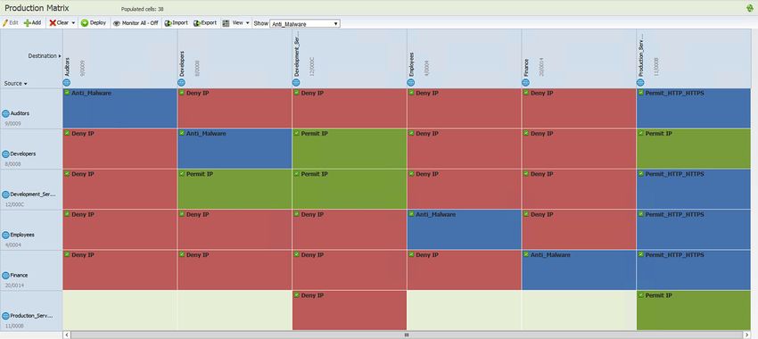
Table of Contents

Table of Contents
Introduction ..................................................................................................................................... 1

Intent-based networking and segmentation...................................................................................... 2

     Understanding virtual networks and SGTs in SD-Access..................................................................................................4

     Enforcement of traffic destined external to the fabric.......................................................................................................9

Defining network segments............................................................................................................ 16

     Virtual networks or scalable group tags.......................................................................................................................... 17

Use cases...................................................................................................................................... 21

     University........................................................................................................................................................................ 21

     Manufacturing................................................................................................................................................................ 22

     Healthcare...................................................................................................................................................................... 24

     PCI and retail.................................................................................................................................................................. 26

     Electric power................................................................................................................................................................ 26

Appendix A: Network segmentation overview: A brief history......................................................... 28

     VLANs and private VLANs.............................................................................................................................................. 28

     Virtual routing and forwarding instances......................................................................................................................... 29

     Cisco TrustSec—Software-defined segmentation.......................................................................................................... 31

Appendix B: References................................................................................................................. 34

Cisco Validated Design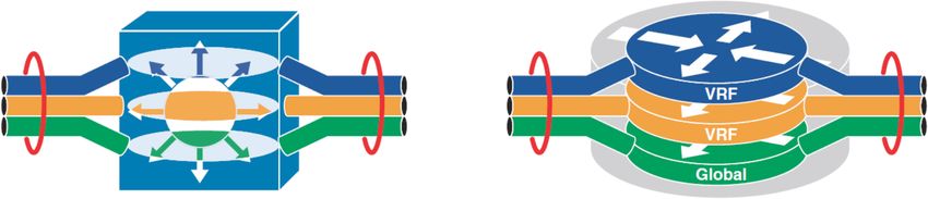
Introduction

Introduction
An ever-growing number of cyberattacks are launched daily against organizations of all types, carried out by
individuals, organized syndicates, and state-sponsored hackers. Whether for purposes of financial gain through
acquiring credit card data, extortion through ransomware, access to personal data for identity theft, or disruption
of services, these attacks are continually growing in frequency and sophistication. Furthermore, with the ever-
growing availability of open-source codebases and tools, these attacks no longer require a high level of skill,
enabling them to be launched by less sophisticated threat actors.
Organizations struggle to identify not only those technologies and products that will protect them but the budget
necessary to acquire, implement, and operate them. Products such as Cisco Firepower® Next-Generation
Firewall and Intrusion Prevention System, Cisco® Web Security Appliance (WSA), Cisco Advanced Malware
Protection, and Cisco Stealthwatch® providing network visibility, and Cisco Identity Services Engine providing
policy and secured network access for authorized users, guests, and IoT devices are all effective in providing
a “defense-in-depth” strategy to protect an organization. Once adopted, the focus shifts to defining an
implementation strategy that will protect an organization’s critical assets and data by enforcing authorized access
to the network while also monitoring communications for anomalous behavior from endpoint to data center.
Another very effective strategy to consider, underlying all other security products, is the use of network
segmentation to reduce the scope of an attack. Network segmentation can be described as the process of
breaking down or splitting a single large network, with a single routing table, into any number of smaller networks
or zones either virtually or logically. With a segmented network, and security controls to enforce policies in and
out of the segment, you
  •• Provide isolation between segments, supporting regulatory compliance

  •• Minimize the attack surface, limiting it to only one segment, thereby restricting the east/west propagation
     of malware

  •• Introduce enforcement points between segments where stateful packet inspection can be implemented

  •• Provide an environment where further micro-segmentation is possible

The purpose of this document is to familiarize you with Cisco Software-Defined Access and its unparalleled
capabilities in implementing network segmentation in your network. Its intent is to assist you in better
understanding the architecture and further assist in strategizing the approach to be taken.
If you are unfamiliar with network segmentation, before proceeding you may want to read Appendix A, which
offers a brief history of network segmentation. We also recommend that you read the TrustSec User-to-Data-
Center Access Control Using TrustSec Design Guide in order to understand the Cisco TrustSec® software-defined
segmentation architecture. It is very important that you have an understanding of the Cisco TrustSec solution
because it is the basis for Scalable Group Tags (SGTs) and their use in group-based access control policies found
within SD-Access. An overview of TrustSec can be found in Appendix A as well.

Cisco Validated Design                                                                                      page 1
Intent-based networking and segmentation
Intent-based networking and segmentation
Originally, network segmentation was aligned to a strategy for improving network stability and performance. Over
time, it has evolved to reflect a security strategy in which the network is segmented or compartmentalized to
enforce a policy by enabling controls within and between segments.
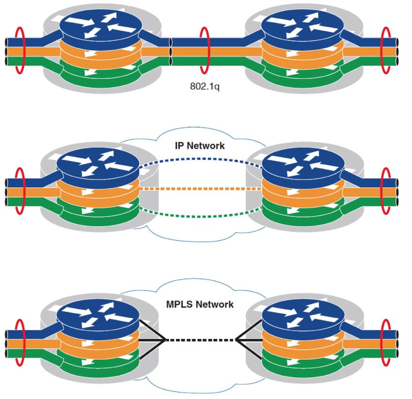
Today, while VLANs and private VLANs still provide rudimentary Layer 2 segmentation of Layer 3 IP subnets
for some organizations, many others have chosen to use VRFs or software-defined segmentation via Cisco
TrustSec as the primary means of segmenting a network. VRFs provide complete isolation of routing and switching
environments, making VRF a common network segmentation technology for a substantial number of organizations
using VRF-Lite through either 802.1Q trunks or GRE or, in many cases, even MPLS as the underlying transport.
Aside from VRFs, however, an increasing number of customers are using Cisco TrustSec to provide logical,
group-based segmentation without the need to support data plane isolation along with the routing/control plane
considerations inherent to VRFs. As will be discussed in the section “Defining network segments” later in this
document, both approaches offer their own unique benefits, and some customers have decided to implement
both technologies. VRFs and Cisco TrustSec software-defined segmentation will continue to be, both now and in
the foreseeable future, extremely effective methods for segmenting the network and, through this segmentation,
whether virtual or logical, extending a security policy.
A network segmentation strategy developed to enforce security policy in support of an organization’s business
requirements is typically not limited to a single location. It could be needed across a campus consisting of multiple
buildings with thousands of devices or across remote sites such as stores or branches, each with a handful of
devices. A given network segment, and the policies it represents, may be extended anywhere within an organization
where one of the business-relevant applications or functions reside. Historically, when implementing VRFs or Cisco
TrustSec, manual configuration of the network infrastructure is unavoidable. Whether extending VRFs through VRF-
Lite or MPLS or enabling the propagation of the Cisco TrustSec SGTs, configuration must be completed manually,
often on a hop-by-hop basis.
With the introduction of Cisco Software-Defined Access (SD-Access) and, more broadly Cisco’s Digital Network
Architecture (DNA), the means by which network segmentation can be implemented are once again evolving. To
quote the “Cisco Intent-Based Networking” white paper:
Intent-based networking solutions enable conventional practices that require the alignment of manually derived
individual network-element configurations to be replaced by controller-led and policy-based abstractions that easily
enable operators to express intent (desired outcome) and subsequently validate that the network is doing what they
asked of it.
Reader tip
For more information about Cisco’s intent-based networking architecture, visit https://www.cisco.
com/c/en/us/solutions/intent-based-networking.html
For the Cisco IBN white paper, visit https://www.cisco.com/c/dam/en/us/solutions/collateral/enterprise-
networks/digital-network-architecture/nb-09-intent-networking-wp-cte-en.pdf?oid=wpren006178
Cisco Validated Design page 2
Intent-based networking and segmentation

One of the key benefits realized as a result of Cisco Intent-Based Networking (IBN) and enabling technologies
such as SD-Access is the ability to ensure that a security policy for compliance exists throughout the
organization. The scope of an IBN thus extends from the data center and cloud environments all the way to the
campus and remote locations, and encompasses even remote access to the network, whether for employees,
contractors, or vendors. Those controllers, which provide the automation and controls that make up the IBN,
reduce risk by assuring that security policies are being applied consistently across the network, and help ensure
that policies are compliant with business requirements. They capture and translate business intent into network
policies and activate them across the infrastructure.
A similar example in the data center, Cisco Application Centric Infrastructure (Cisco ACI™), powered by the Cisco
Application Policy Infrastructure Controller (APIC), offers an architecture that can translate business requirements
into secured zones or enclaves. With Cisco ACI deployed, contracts or policies can be created that allow
only specific communications between tiered applications, as well as access to external resources, whether
applications or users, while blocking all other unauthorized access. Within the Cisco ACI policy model, both VRFs
as well as group-based Endpoint Groups (EPGs)—similar in many ways to SGTs, even to the extent that they can
be translated—are used to provide segmentation. Contracts, defined through the use of EPG security policies and
application network profiles, are applied to controlling communications, both into and out of the data centers as
well as within it between applications and data repositories.

           Reader tip

           For more information regarding the APIC policy model, refer to the white paper at https://www.cisco.
           com/c/en/us/solutions/collateral/data-center-virtualization/application-centric-infrastructure/white-
           paper-c11-731310.html

Within the SD-Access architecture, Cisco DNA Center™ and Cisco ISE work in unison to provide the automation
for planning, configuration, segmentation, identity, and policy services. Cisco ISE is responsible for device
profiling, identity services, and policy services, dynamically exchanging information with DNA Center. DNA Center
consists of the automation and assurance components that work in unison to form a closed-loop automation
system, enabling the configuration, monitoring, and reporting required to realize the full extent of the Cisco IBN in
campus environments.
When DNA Center is implemented, ISE is still deployed as a separate appliance providing identity and policy
services for the SD-Access campus fabric. When creating SGTs through the DNA-C user interface, the ISE user
interface is cross-launched and the task completed there; ISE maintains all of the scalable group information later
used in DNA-C for policy creation. Although the policies and corresponding contracts are created at DNA-C, both
are communicated back to ISE through representational state transfer application programming interface (REST
API) calls. ISE then serves as the single point of reference for SGTs, policies, and contracts (SGACLs), which are
then dynamically distributed to the network infrastructure.
Segmentation within SD-Access is enabled through the combined use of both Virtual Networks (VN), which
are synonymous with VRFs, and Cisco TrustSec Scalable Group Tags (SGTs). Whereas segmentation can be
accomplished through the use of intent-driven or purpose-built virtual networks alone, Cisco TrustSec SGTs
provide logical segmentation based on group membership. Cisco TrustSec provides an additional layer of
granularity, allowing you to use multiple SGTs within a single VN providing micro-segmentation within the VN.

           Reader tip

           For more information on SD-Access, refer to https://www.cisco.com/c/en/us/solutions/enterprise-
           networks/software-defined-access/index.html as well as the Cisco Validated Design SD-Access Design
           Guide at https://www.cisco.com/c/en/us/solutions/design-zone.html.

Cisco Validated Design                                                                                             page 3
Intent-based networking and segmentation
Reader tip
Prior to SD-Access, the acronym SGT referred to “security group tag.” It has since been changed to
“scalable group tag,” as in the future SGTs may be used for other purposes. Quality of Service (QoS)
and policy-based routing are two such examples, having been implemented in TrustSec prior to
Software-Defined Access (SD-Access).
Although this design guide focuses specifically on segmentation and policy constructs in SD-Access, it is
important to understand how SD-Access and other technologies, such as SD-WAN, interact with data centers
based on Cisco ACI, as well as with infrastructure that has implemented either Cisco TrustSec or VRFs. The
importance of understanding how these technologies intersect and how policies are translated between
environments cannot be overlooked as organizations begin the process of migrating to a full IBN model. Existing
segmentation strategies, whether Cisco ACI, VRFs, or Cisco TrustSec, will influence decisions regarding how
virtual networks at the macro-segmentation level and scalable groups at a micro-segmentation level should be
organized and populated within an SD-Access fabric.
Understanding virtual networks and SGTs in SD-Access
Virtual networks
Virtual networks, like VRFs described earlier, provide complete isolation between traffic and devices in one VN
and those in other VNs. Within the SD-Access fabric, information identifying the virtual network is carried in the
VXLAN Network Identifier (VNI) field within the VXLAN header as seen in Figure 1.
Figure 1. VXLAN-GBP header
0 1 2 3
0 1 2 3 4 5 6 7 8 9 0 1 2 3 4 5 6 7 8 9 0 1 2 3 4 5 6 7 8 9 0 1
+-+-+-+-+-+-+-+-+-+-+-+-+-+-+-+-+-+-+-+-+-+-+-+-+-+-+-+-+-+-+-+-+
Scalable
|G|R|R|R|I|R|R|R|R|D|R|R|A|R|R|R| Group Policy ID
Group Tag
+-+-+-+-+-+-+-+-+-+-+-+-+-+-+-+-+-+-+-+-+-+-+-+-+-+-+-+-+-+-+-+-+
V X L A N N e t w o r k I d e n t i fi e r ( V N I ) Reserved
+-+-+-+-+-+-+-+-+-+-+-+-+-+-+-+-+-+-+-+-+-+-+-+-+-+-+-+-+-+-+-+-+
VXLAN -GBP
draft-smith-vxlan-group-policy-04
VXLAN
FCS
Outer MAC Header Outer IP Header Outer UDP Header Original Layer 2 Frame
Header
Unlike its legacy VRF counterparts, the SD-Access fabric does not require a separate routing table per virtual
network, within the SD-Access fabric as LISP is used to provide control plane forwarding information. External to
the SD-Access fabric, at the SD-Access border, the virtual networks map directly to VRF instances, which may
be extended beyond the fabric. Path isolation techniques such as VRF-Lite or MPLS may be used to maintain the
isolation between VRFs. Additionally, SD-Access IP addressing information represented by the fabric Endpoint
Identifier (EID) can be redistributed into a routing protocol such as BGP, EIGRP, or OSPF for use in extending the
virtual networks.
By default, DNA Center has a single virtual network, the DEFAULT_VN, that all users and endpoints belong to.
Upon DNA Center integration with ISE, the default virtual network is populated with scalable groups from ISE.
These scalable groups can be used in the DEFAULT_VN or new virtual networks can be defined.
Cisco Validated Design page 4Intent-based networking and segmentation Because VRFs external to the fabric isolate communications between them by using separate routing tables per VRF, it is necessary to forward traffic to an external network device to enable these communications if desired. A firewall, Layer 3 switch, or router can then be used to leak routing information, maintained in each VRF, thus enabling communication between virtual networks while also providing a control point to enforce established security policies. As discussed earlier, these network devices are commonly referred to as “fusion” firewalls or routers. Today these fusion routers and firewalls must be external to the fabric. Scalable group tags As discussed previously, SGTs are represented by a 16-bit group identifier that is associated with the scalable groups, the membership of which is based on business roles or functions. By default, there are a number of predefined scalable groups along with an associated hexadecimal tag ID. You also can define new scalable groups along with a tag ID of your choosing. If we think of user roles in a healthcare environment as an example, we could organize users into doctors, nurses, imaging technicians, pharmacy, patients, and guests. Likewise, we could assign unique SGTs to different devices, such as IP cameras, HVAC control, keypads/swipes, and digital signage. Little has changed relative to how SGTs are used within SD-Access when compared to Cisco TrustSec in today’s non-fabric networks. SGTs continue to provide a means by which devices or users can be logically segmented from one another. Future development will likely change what information or intent can be derived from an SGT. The primary difference in SGT creation and use within SD-Access is that the process of defining SGTs is started at DNA Center and then used within the virtual networks established by an organization. As the global routing table is reserved for use in the underlay of the SD-Access fabric, the SGTs and the logical segmentation they represent, will be created in the DEFAULT_VN for use there or for assignment to other user-created virtual networks. Today, a scalable group can be used only in a single virtual network. Propagation of the SGT in an SD-Access network is no longer performed on a hop-by-hop basis as with TrustSec inline tagging, but is carried within the VXLAN header, as shown earlier in Figure 1. As can be seen in the figure, the SGT and VNI are both maintained in the VXLAN header for communication between VXLAN tunnel endpoints in the SD-Access fabric. As we have discussed, segmentation within SD-Access takes place at both a macro and a micro level through virtual networks and SGTs, respectively. Virtual networks are completely isolated from one another within the SD-Access fabric, providing macro-segmentation between endpoints within one VN from other VNs. By default, all endpoints within a virtual network can communicate with each other. Because each virtual network has its own routing instance, an external, non-fabric device known as a fusion router or firewall is required to provide the inter-VRF forwarding necessary for communications between the VNs. It is at this fusion device that a policy can be implemented based on a standard IP-based ACL, scalable group tags, or a combination of both. You can also enforce policies that have been defined at DNA Center for traffic within virtual networks based on the SGTs that endpoints are assigned. These policies, or SGACLs, may be as simple as permit/deny or may be based on Layer 4 access control entries explicitly permitting/denying specific TCP/UDP ports and are called Contracts in DNA Center. The policies and associated contracts are configured in DNA Center and then communicated through the REST API to ISE. ISE then updates the edge nodes with only those policies for SGTs associated with the attached devices. Enforcement occurs upon egress where the destination is attached. Figure 2 depicts the use of a fusion firewall for communications between virtual networks as well as traffic destined elsewhere in the network. Using standard ACLs or group-based policies with SGTs, firewall rules are defined at the fusion firewall controlling traffic between endpoints. The benefit of enabling TrustSec on the firewall is twofold. The first is in the ability for you to enforce policies for either externally bound or inter-VN traffic based on SGT as opposed to all IP addresses. The second is in the ability to propagate tagged traffic beyond the SD- Access fabric, if inline tagging has been enabled in your network, to other non-fabric areas in the LAN or WAN, thereby extending your group-based policies throughout your network. The firewall in Figure 2 does not need to use SGT information and can simply use standard IP-based access lists as well. Cisco Validated Design page 5
Intent-based networking and segmentation

           Reader tip

           The fusion firewall(s) as discussed in this document is considered to be Layer 3 adjacent to the SD-
           Access border node as well as any external infrastructure.

Firewalls that use SGTs in the rules are called Scalable Group Firewalls (SGFWs). SGFWs receive only the names
and scalable group tag value from ISE; they do not receive the actual policies/rules. Unlike switches, where
SGACLs are configured at DNA Center and deployed by ISE, SGT-based rule definition is performed locally at the
SGFW through either the CLI or other management tool.

           Reader tip

           For further information regarding SGFW configuration, refer to Access Control Using Security Group Firewall.

Figure 2. Policy enforcement with a fusion firewall

                                                 DNA-C
           SD-Access                                                         ISE
                                                           pxGrid
                                                                             SG
                                                                               T
                                                                                   in               Policy created
                                                                                     fo
                                                                                          on        at FW based
                                                                                            ly
                                                                                                    on SGT

             Building VN                           CO               Border
                                                                    Node

               CO         HV           IP        PH
             Contractor   HVAC      IP Camera   Physical                                                             Enterprise Core
                                                Security
                                                                                                                     or Data Center

                                                                              Fusion
             Campus VN                                                        Firewall
                                                      PR

               EM          FA         ST         PR
             Employee     Faculty    Student     Printer

             Default VN

In Figure 2, traffic sourced from the Building VN and destined to either the Campus VN or external to the fabric,
can either be forwarded or dropped based on the policy implemented on the firewall based on scalable groups.
When using firewall rules based on scalable groups and IP addresses or network objects, there are no additional
considerations other than assuring that there are dedicated interfaces or sub-interfaces for each VN. The major
drawback to the use of IP addresses in the firewall rules, however, is that if the endpoint addressing changes, the
firewall rules must be updated to reflect these new addresses.

Cisco Validated Design                                                                                                                 page 6
Intent-based networking and segmentation
If you decide to implement a SGFW to enforce policy based on SGTs in addition to the interfaces dedicated to each
VN, you need to make sure that the scalable group information associated with each endpoint sourcing the traffic
is propagated to the SGFW and available for use rule creation. Additionally, as discussed in the next section, if you
want to enforce your policy at the SGFW using only SGTs, the destination IP-SGT mappings will also be required.
Technical tip
The SGFW may be either an ASA running ASA OS or a Cisco Firepower™ Next-Generation Firewall
(NGFW) appliance running either ASA OS or Firepower Threat Defense (FTD) software. In the case
of ASA OS, you can use any combination of source/destination SGTs or IP addresses in the firewall
rules. If you are using NGFW FTD software, only the source SGT is specified and the destination will
be an object based on an IP address. Another difference is that SGT Exchange Protocol over TCP
(SXP) is used when the firewall is running ASA OS.
Propagating scalable group tags for enforcement
To implement a SGFW on the fusion firewall, scalable group information must be available for the traffic entering
the firewall and optionally the destination if all enforcement is to occur at the SGFW. As with non-SD-Access
implementations of Cisco TrustSec, enforcement will occur at the first network device that is able to derive the
source SGT while also having the IP-to-SGT mapping information of the destination. Before discussing SGFW
enforcement considerations, though, we will first discuss SGT propagation.
You can propagate SGT information by using Cisco ISE to advertise the IP-to-SGT mappings through SXP or pxGrid
to the SGFW. You need to configure Cisco ISE to exchange scalable group names and the associated 16-bit SGT
ID with the firewall. When SXP or pxGrid are used, as untagged traffic arrives at the SGFW, the scalable group
mapping database will be checked and the source traffic associated with the SGT ID learned from ISE.
Caution
For SD-Access, the propagation of scalable group tag information for fabric endpoints to the fusion
firewall is supported only by using SXP or pxGrid between ISE and the fusion firewall. Inline tagging is
not supported between the SD-Access border node and the fusion firewall or other devices that are
Layer 3 adjacent to the border node at this time.
Reader tip
For further information regarding SGFW configuration, refer to Access Control Using Security
Group Firewall.
Additionally, when the firewall is running the ASA OS operating system, ISE will use SXP to advertise
IP-to-SGT mappings and in the case of a Cisco Firepower NGF running the FTD OS, Cisco ISE will
use pxGrid for advertisement of IP-to-SGT mappings.
The use of SXP or pxGrid to advertise IP-to-SGT mappings is dependent on the SGFW operating system. If
running ASA OS on either an ASA or Cisco Firepower appliance, SXP is used to advertise the IP-SGT mappings
of the endpoints attached to the fabric. If using the FTD software on the Firepower NGFW, pxGrid is used to
publish the mappings to the Firepower NGFW. You can then configure ISE to advertise the mappings of devices
connected to the fabric edge nodes, learned during RADIUS authorization as discussed in the tip that follows. This
configuration will then populate the SGFW with the IP addresses and the associated SGTs for devices connecting
to the fabric, as depicted in Figure 3.
Cisco Validated Design page 7Intent-based networking and segmentation
Reader tip
Within ISE, on the TrustSec > Settings page, it is possible to add RADIUS session mappings
as IP-to-SGT mappings for SXP advertisement as well as publishing them on pxGrid. Refer
to the following screenshot:
This mapping will work for all Cisco switches capable of dot1x/MAB authentication as well
as any third-party switch using ISE as a RADIUS server. For Cisco switches, this mapping
is available regardless of its having been deployed as a fabric edge node or in a non-fabric
portion of the network.
Figure 3. SXP enabled to fusion firewall
EM SDA Fabric SXP or pxGrid
(no inline tagging used)
IP
CO
SGT carried natively Enterprise Core
in the SDA fabric SGFW/Fusion FW or Data Center
HV
FA
Border Possible
IP Nodes enforcement points
Campus VN
Building VN
Additionally, you can advertise IP-to-SGT mappings for servers or other non-fabric endpoints manually created
at ISE or learned dynamically via ACI integration when an Application Policy Infrastructure Controller (APIC)
controlled ACI fabric is present, to enforce your policy on communications destined external to the fabric. The
manual creation of IP-SGT mappings at ISE is obviously not limited to endpoints outside of the SD-Access fabric
but is also applicable to endpoints that may not use dot1x or MAB authentications within the fabric and for which
manual mappings must be created.
If you want to be able to propagate the SGT beyond the SGFW into other areas of your network without
enforcement occurring at the SGFW, having inline tagging enabled at the egress interface of the firewall will
be most efficient because the SGFW will simply forward the frames with the SGT embedded; this forwarding
will occur for either firewall OS you are running. As the traffic arrives at the SGFW, it will perform an IP-to-SGT
Cisco Validated Design page 8Intent-based networking and segmentation
lookup, check for a policy, and, if permitted and the egress interface of the SGFW is enabled for inline tagging,
will forward the traffic with the associated SGT in the CMD field of the Ethernet header. This scenario naturally
assumes that Cisco TrustSec® inline tagging has been enabled on the infrastructure beyond the SGFW/fusion
firewall, as depicted in Figure 4.
Reader tip
For more information about Cisco TrustSec inline tagging, please refer to the
User-to-Data-Center Access Control Using TrustSec Deployment Guide and the
User-to-Data-Center Control Using TrustSec Design Guide.
Figure 4. Inline tagging on egress from fusion firewall
SDA Fabric Possible
EM
enforcement points
IP SXP or pxGrid
CO
SGT carried natively Enterprise Core
in the SDA fabric SGFW/Fusion FW or Data Center
HV
FA
Border Inline tagging enabled
IP Nodes for external or inter-VN traffic
Campus VN
Building VN Inline tagging
SXP advertisement to other areas of the network is another possibility; it is discussed in greater detail in the
enforcement section that follows.
Enforcement of traffic destined external to the fabric
Three options exist for the enforcement of a policy based on SGTs for traffic destined external to the
SD-Access fabric:
1. Enforce at the fusion firewall serving as an SGFW.
2. Enforce at either the destination or somewhere else in the path.
3. Enforce at the border node.
The use of the SD-Access border node for SGT-based enforcement is applicable only for fabric traffic destined
outside of the fabric. Depending on the type and scale of outbound traffic, it may require considerable software
and/or hardware resources on the SD-Access border node. For these reasons, it is beyond the scope of this
document to discuss the various platforms and the differences in scalability as to the number of IP-to-SGT
mappings and SGACLs supported.
As discussed, enforcement based on SGTs is based on the ability of the enforcement device to derive both the
source and destination SGTs. The SGT information for fabric endpoints is propagated in the VXLAN header for
traffic reaching the border node. The SGT of the destination, however, is not known at the border node and so
must be advertised by Cisco ISE through SXP; Cisco firewalls are not supported as border nodes and hence this
Cisco Validated Design page 9Intent-based networking and segmentation
discussion is applicable only to Cisco routers and switches that are supported. Several points must be considered
when enabling SXP learning of IP-SGT mappings at a network device such as a router or a switch:
•• When a network device is defined at ISE for TrustSec policy enforcement, as the network device learns
mapping information for an SGT, it will communicate with ISE to get the policies associated with that SGT as
a destination. The SGACLs downloaded, in the case of a router or switch, will consume memory or TCAM,
respectively. Numerous SGTs with their associated policies may lead to heavy memory usage in routers and
TCAM exhaustion in switches. Ultimately, some SGACLs may not be installed.
•• Network devices have well-defined limits as to the number of IP-to-SGT mappings they can store. These
mappings will consume memory as the numbers of mappings increase. If the supported numbers are exceeded,
mappings will not be installed in memory and as a result, policies specific to those mappings will not be enforced.
In lieu of these considerations, it is beyond the scope of this document to discuss the various platforms supported
as border nodes and the differences in scalability as to the number of IP-to-SGT mappings and SGACLs supported.
Reader tip
For more information regarding policy enforcement on an SD-Access border node, please refer to
Enforcing Policy on an SD-Access Border Node.
For more information about platform scalability regarding the number of IP-to-SGT mappings and
SGACLs, refer to the TrustSec System Bulletins.
Option 1: Enforcement at fusion firewall serving as SGFW
The first option allows you to enforce group-based policies for all traffic leaving the SD-Access fabric at the
fusion SGFW. There is no need to propagate the SGT of the fabric endpoints beyond the SGFW. With the first
option, as discussed, you will have ISE advertise the IP-to-SGT mappings of the authenticated fabric endpoints
to the SGFW. You will then need to decide whether the policies at the SGFW will use scalable group tags for the
destination or IP addresses.
Depending on whether you are using ASA OS on the fusion firewall or FTD, you have different options for
identifying the destination in the rules. With ASA OS, remember that any combination of SGTs or IP addresses can
be used regardless of source and destination. Will need to be updated when FTD supports destination SGT.
If the policies you want to create consist of a source SGT and a destination IP address at the SGFW, regardless of
operating system, and propagation of source SGT information is established through SXP or pxGrid between ISE
and the SGFW, you will be able to proceed with rule creation and enforcement.
If you are running ASA OS on your SGFW and you decide that you want to use SGT information for both source
and destination in your rules, whether external or in another virtual network, you will need to advertise the IP-to-
SGT mapping information for these destinations to the SGFW with SXP. Remember the basic rule that enforcement
based on SGT will occur at the first network device that has the IP-to-SGT mapping for the destination.
Reader tip
Concerns over IP-to-SGT scaling and SGT-based enforcement at a Cisco firewall regardless of
operating system running are virtually nonexistent. Most current models of Cisco ASA firewalls and
all FTD-based Firepower appliances typically scale to between 750,000 and 2 million IP-to-SGT
mappings. Rules based on SGTs actually can consume far less memory than comparable rules based
on IP addresses and/or network objects. For more information about platform scalability regarding the
number of IP-to-SGT mappings, refer to the TrustSec System Bulletins.
Cisco Validated Design page 10Intent-based networking and segmentation
The two ways to populate the SGFW running ASA OS with the destination IP-to-SGT mappings are by creating
static mappings on the SGFW or using SXP. The recommended approach is for centralized configuration at ISE,
where you can manually create those mappings and advertise them to the SGFW. The mappings created at ISE
for advertisement to the SGFW can be either a host address or a subnet. Additionally, as just discussed, if you
have an ACI data center, you can integrate ISE with APIC, thus enabling the dynamic creation of the IP-to-SGT
mappings for the servers in the ACI fabric. These mappings can then be automatically advertised to the SGFW as
well. This deployment is depicted in Figure 5.
Figure 5. SGFW enforcement for external traffic
SXP for fabric SXP for mappings of
endpoints external destinations Server mappings
created manually at ISE
EM SDA Fabric or dynamically created
via ACI integration
IP
CO
SGT carried natively
Enterprise Core
in the SDA fabric SGFW/ASA-OS
or Data Center
HV
FA Enforcement points
Border
IP Nodes
Campus VN
Building VN
Option 2: Enforcement at destination or in path to destination
For enforcement at a destination or at a device along the path toward the destination, the IP-to-SGT mapping of
that destination endpoint must be present at the enforcement device. If enforcement will be at the network device
that the destination is attached to, that endpoint must be “classified” or associated with an SGT. Classification or
creation of the IP-to-SGT mapping can be performed locally on the network device dynamically through 802.1x
or MAB; or statically through IP-to-SGT, subnet-to-SGT, VLAN-to-SGT, or port-to-SGT through the device CLI,
based on the capabilities of the platform. Alternatively, the destination mappings could be created at ISE and
advertised through SXP to the destination switch. If enforcement is desired at a network device along the path to
the destination, SXP or static classification at the intermediate device will be required.
Reader tip
For complete information regarding Cisco TrustSec classification, please refer to either the
User-to-Data-Center Access Control Using TrustSec Deployment Guide or the User-to-Data-Center
Control Using TrustSec Design Guide
Cisco Validated Design page 11Intent-based networking and segmentation
In addition to the destination IP-to-SGT mapping, the second option assumes that the SGT of the SD-Access
fabric endpoint will be propagated to the enforcement point. You will need to either enable Cisco TrustSec inline
tagging at egress from the fusion firewall or use SXP to propagate the SGT of the source, fabric endpoint, to the
destination or enforcement point.
Inline tagging is always the most scalable approach because the SGT is embedded in the Ethernet header of the
traffic toward the destination. Unlike SXP, all processing of the SGT is performed in hardware, whereas SXP will
consume memory and processor to store and update the mappings. In order to support inline tagging, all links
between the fusion firewall and the enforcement point for the destination must be manually enabled for TrustSec.
This enablement is performed on each device on a hop-by-hop basis.
One additional point to note with inline tagging enabled is that you will not only be able to enforce TrustSec
group-based policies for traffic sourced in the fabric at the external destination, but you will also be able
to enforce policies restricting inbound traffic from servers to fabric endpoints at the fusion firewall. This is
possible as long as servers or other external destinations are classified with an SGT locally, as previously
discussed, allowing the traffic to be tagged remotely and propagated back toward the fabric over the non-fabric
infrastructure enabled for inline tagging. This is depicted in Figure 6.
Reader tip
For more information regarding TrustSec inline tagging configuration, please refer to the User-to-
Data-Center Access Control Using TrustSec Deployment Guide and the User-to-Data-Center Control
Using TrustSec Design Guide.
For additional information regarding platform support for inline tagging, refer to the TrustSec Platform
Support Matrix.
Figure 6. TrustSec inline tagging enabled in non-SD-Access infrastructure
SXP for fabric Policy for SGTs associated
endpoints with servers downloaded
from ISE by switch
SGT transported to
EM SDA Fabric destination via inline tagging
where policy is enforced
IP
CO
SGT carried natively Enterprise Core
in the SDA fabric. SGFW/ASA-OS or Data Center
HV
FA
Inline tagging
Border
ST Nodes Inline tagging enabled
Campus VN Enforcement points
for fabric endpoint traffic
Building VN Policy enforced for server
to fabric endpoint traffic
Cisco Validated Design page 12Intent-based networking and segmentation
If you decide to use ISE and SXP as opposed to inline tagging from the fusion firewall, you will need to configure
ISE to advertise the IP-to-SGT mappings created during fabric endpoint AAA authorization to the network, as we
have discussed. You will then need to configure SXP between ISE and the network device(s) at which you select
to enforce the policy. Two points that were made earlier regarding enabling SXP learning of IP-SGT mappings at a
network device such as a router or a switch are covered in detail here again because you must not overlook them:
•• When a network device is defined at ISE for TrustSec policy enforcement, as the network device learns
mapping information for an SGT it will communicate with ISE to get the policies associated with that SGT as
a destination. The SGACLs downloaded, in the case of a router or switch, will consume memory or TCAM,
respectively. Numerous SGTs with their associated policies may lead to heavy memory usage in routers and
TCAM exhaustion in switches. Ultimately, some SGACLs may not be installed.
•• Network devices have well-defined limits as to the number of IP-SGT mappings they can store. These mappings
will consume memory as the numbers of mappings increase. If the supported numbers are exceeded, mappings
will not be installed in memory and as a result, policies specific to those mappings will not be enforced.
You should keep these considerations in mind as you select those devices that will require the SXP mappings
for enforcement purposes. Also, as previously discussed, remember that the Cisco firewalls when chosen as
enforcement points are extremely scalable. Figure 7 depicts SXP enforcement at a network device that is external
to the SD-Access fabric.
Reader tip
For the latest information regarding platform TrustSec scalability for the number of mappings
supported, SXP, and SGACLs, please refer to the TrustSec System Bulletins.
For additional information regarding SXP, please refer to the Using SXP and SXP Reflectors document
in Cisco Communities for TrustSec.
Figure 7. SXP to enforcement point external to the fabric
Policy for SGTs associated
with servers downloaded
from ISE by switch
SDA Fabric SXP for advertisement of
EM
fabric endpoint mappings
IP
CO
Enterprise Core
SGFW/ASA-OS or Data Center
HV
FA Untagged traffic arrives
at destination where
based on the SXP
Border
mapping it is associated
IP Nodes
Campus VN with the advertised SGT
Building VN Enforcement points and policy enforced
Cisco Validated Design page 13Intent-based networking and segmentation
One difference that you will encounter if choosing to use SXP as opposed to inline tagging is that without additional
configuration, other than that described previously, enforcement of server traffic or other external endpoints to a
fabric endpoint based on SGT is not possible. This additional configuration is required because the external traffic
will arrive at the fusion firewall without an SGT and hence is unusable in a SGT-based policy.
To configure this, you must propagate the IP-to-SGT mappings for the external devices to the fusion firewall for
use as the source SGT. This will then allow you to enforce policies where the source is external to the fabric and
the destination is a fabric endpoint, as depicted in Figure 8.
Figure 8. Enforcing policy for external traffic destined to fabric
EM SDA Fabric SXP for advertisement of both
fabric and external endpoint
mappings
IP
Fusion FW-ASA-OS
CO
Enterprise Core
or Data Center
HV
FA
Untagged external traffic
Border arrives at fusion firewall. As
IP Nodes SXP mappings are present, Enforcement points
Campus VN
fusion firewall will enforce
Building VN
policies based on SGT
Enforcement of traffic within and between virtual networks
Within each VN, one or more scalable groups can be defined providing SGT-based microsegmentation within that
VN. Policies defining communications between SGTs within each VN are defined at DNA-C, communicated to ISE
through REST API, and subsequently distributed by ISE to the edge nodes of the SD-Access fabric. As endpoints
attach to the edge nodes, the edge node will request the applicable policy for that SGT if not already present,
and install it in TCAM. For enforcement within the VN, the only requirements are that the policies and associated
contracts have been created for the VN, defining what communications between SGTs are permitted or dropped.
You can also enforce Policies using SGTs to permit or deny traffic between VNs. When you create VNs, you will
have the option to assign scalable groups to that VN. When building a policy in DNA-C you will specify a source
and destination SGT. If the policy you are creating is going to use an SGT from another VN, you will need to define
that SGT as being VN agnostic as seen below.
As with enforcement between the fabric endpoints and external destinations, you have two options for policy
enforcement for traffic between VNs:
1. Enforce at the fusion firewall serving as an SGFW
2. Enforce at the destination edge node.
Because scalable groups can be assigned only to a single VN today, it is not possible to create a VN policy in
DNA-C where the source or destination SGT of one VN also resides in another VN.
Cisco Validated Design page 14Intent-based networking and segmentation
For enforcement between VNs using a fusion firewall, you will configure ISE to advertise the IP-SGT mappings
derived during fabric endpoint authorization, as discussed earlier. These mappings are used at the SGFW in
rule creation to enforce your policy. Again, if you are using ASA OS on your ASA or Firepower SGFW, you will
be able to create your rules using any combination of SGTs and IP addresses as sources or destinations. If,
however, you are using the Firepower FTD, your rules need to use destination IP addresses. Figure 9 depicts the
scenario described.
Figure 9. Enforcement of traffic within and between virtual networks
SXP for fabric
EM SDA Fabric endpoints
IP
ST
SGT carried natively Enterprise Core
in the SDA fabric SGFW/ASA-OS or Data Center
HV
FA Possible
enforcement points
Border
IP Nodes
Campus VN
Building VN
Cisco Validated Design page 15Defining network segments
Defining network segments
The decision to create network segments, whether virtual or logical, should be driven by the organization’s
business requirements. But what does that really mean? First and foremost, what are the goals of segmenting
the network?
Implementing network segmentation allows you to define segments, whether virtual (virtual networks) or logical
(SGTs), that are dedicated to a specific business application or function for security reasons. These segments can
have well-defined policies governing access to a segment and the ability to limit communications between them.
When implementing segmentation, you minimize the network attack surface to, at most, that segment, while
additionally defining security policies within and outside of the network segments in the case of virtual networks,
or between and within logical segments in the case of SGTs.
As previously discussed, SD-Access offers both network segmentation through the use of virtual networks as well
as “logical” segmentation through the use of SGTs within each virtual network. Realistically, you could decide to
use all virtual networks with a single scalable group in each or, alternatively, a single “user” virtual network with
multiple scalable groups.
The approach taken will depend largely on whether there is a need for complete isolation of an application or
business function. In cases such as Payment Card Industry (PCI) and guest networks, the complete isolation
found with a virtual network is likely the best choice. When using a virtual network, the scope of regulatory
compliance, for example, is limited to access to the virtual network and communications within it. Alternatively,
scalable groups with policies controlling communications between tags can provide the necessary segmentation
“logically” for point-of-sale (POS) machines and card readers. In the case of PCI, though, you will need to be
prepared to demonstrate isolation between the PCI tag and other SGTs belonging to that virtual network. There is
no single correct answer, and most customers will likely choose a combination.
Some examples of where virtual networks might be used are:
•• PCI: POS machines, card readers, and payment card gateways
•• Electrical power: Separation of generation, transmission, and corporate networks
•• Building controls: Heating, cooling, lighting, and security systems
•• Manufacturing floors: Isolating the floor from the corporate network
•• Trading floors
•• Management of network infrastructure
•• Research and development: Isolating the research environment from the corporate network.
•• University dormitories: Isolating them from the campus network and applications
•• Healthcare clinical environments: Bedside monitors, infusion pumps, MRI, ultrasound, and X-ray
•• Guest networks
Some examples of where SGTs might be used are:
•• PCI: Inventory scanners, card readers, POS
•• Healthcare clinical environments: Bedside monitors, infusion pumps, MRI, ultrasound, X-ray, doctors, nurses,
building controls.
•• University: Students, professors, guests, building controls, and security systems
Cisco Validated Design page 16Defining network segments
•• Business functions such as human resources or finance
•• Security systems and other business controls
•• Guest access
•• Contractor access
•• Business partners
•• Quarantine and remediation
•• Network administration
As can be seen from the above examples, there may be a great deal of overlap where virtual networks, SGTs, or
a combination may be used to segment the network. Hence, as we discuss the topic of segmentation we really
need to be able to make a distinction as to which methods will satisfy the business security requirements without
creating unnecessary design complexity.
Virtual networks or scalable group tags
In the previous sections, we have gone through the various segmentation technologies used both with and
without SD-Access. What are the business requirements driving the need for segmentation?
Virtual networks
It is often very easy to identify those requirements that compel an organization to completely isolate segments
from one another, as in virtual networks and VRFs. Typically, this requirement is established in order to attain
regulatory compliance by maintaining security controls between various types of business communications.
When evaluating whether or not a specific business function or application warrants its own virtual network, it is
important to assess the following criteria:
•• Does the application or business function as well as the devices accessing it extend from the edge of the
network into the core?
•• Are the user and device communications primarily limited to that virtual network, with only limited access
required in or out of the virtual network?
•• Within a virtual network, will communications between devices be allowed?
•• Will the scope of a network audit for regulatory compliance be reduced with the isolation enabled by a virtual
network or VRF?
Generally, if the answers to all of the above are yes, this may sway the decision to define a virtual network or VRF
for these applications and functions. When SD-Access has been deployed, routing complexity within the fabric
is eliminated by virtue of the overlay’s VXLAN data plane and LISP control plane; the routing considerations are
moved to the edge of the fabric. At the border of the fabric there will still be a need to use either a fusion router
or firewall for any necessary route leaking between SD-Access virtual networks and the external networks.
An example of when a separate virtual network would be useful is for PCI Data Security Standard (PCI-DSS)
compliance, where security controls must be implemented restricting all access to cardholder data and transmissions.
Placing all devices that will either collect, store, or transmit credit card transactions within a virtual network will
drastically reduce the scope of a PCI audit, providing limited access to that environment with the appropriate policy
enforcement logging capabilities.
Cisco Validated Design page 17Defining network segments A second example of the use of virtual networks can likewise be found in the electrical power industry. In this industry, a need exists to maintain complete isolation between networks identified as supporting critical infrastructure, namely power generation and transmission, and normal corporate operations. In this example the extremely limited communications that are required between networks is permissible only through stateful firewalls. Other similar examples of the use of virtual networks and the need to isolate communications within them can be found in manufacturing floors, building systems, and guest networks. From a manufacturing perspective, the threat of loss of intellectual property is one of the main issues, but of equal concern is the need to isolate the factory floor because the Internet of Things (IoT) has become vulnerable to malware that may literally take a company’s manufacturing hostage. Building systems such as HVAC, secure entry, and video surveillance should likewise be isolated from the rest of an organization’s networks, providing only limited access to those in maintenance or security. Finally, facilitating a guest network is a perfect example of an instance where the isolation offered by a virtual network enables the organization to grant only Internet access and nothing else. In all of these examples it is apparent that the use of virtual networks reduces the complexity of enforcing a security policy by strategically limiting access to only those that need it, using only specific protocols, while also offering rich logging capabilities when firewalls are used as fusion devices controlling inter-virtual network or traffic destined for outside the SD-Access fabric. When considering the number of virtual networks that need to be defined, the most important consideration is the number of virtual networks supported across the network devices comprising the SD-Access fabric. Virtual networks are a fabricwide construct. As such, if you define 15 virtual networks, for example, all fabric devices regardless of definition as an edge node or border node must be able to support 15 virtual networks. This consideration will typically come into play at the edge nodes where they may be some combination of a Catalyst 3850 or 3650. So, for example, the Catalyst 3850 and 3650 Switches support a maximum of 32 virtual networks, whereas DNA Center 1.1.3 supports up to 64 virtual networks with the Catalyst 9300 supporting more. Hence with Catalyst 3850s installed in a fabric running DNA Center 1.1.3, you will be limited to 32 virtual networks. Also, when considering the number of virtual networks that need to be defined, another important consideration is that if communications between virtual networks is a requirement, some form of route leaking will be required. For example, if a virtual network was dedicated to employee devices only and a second virtual network was established for collaboration devices only, it would be necessary to provide a means of route leaking for collaboration applications such as Cisco Jabber® or Cisco Spark™ on employee devices to communicate with IP phones, Cisco Spark Boards, or video endpoints. In essence, you need to concern yourself not only with ensuring that route leaking is enabled for the appropriate address ranges, but also, from a policy perspective, with ensuring that you have identified all of the UDP ports that will have to be allowed for successful communications. Likewise, the creation of separate virtual networks based on business functions such as HR, finance, and accounting, or on types of users such as students, faculty, and administration and the associated route leaking that would be required could become quite cumbersome. In these examples, the use of scalable groups to segment the users within a single virtual network should be considered as well. As part of the routing considerations with SD-Access, you also need to understand that new IP addressing strategies need to be implemented for creation of the underlay network as well as for use within each of the virtual networks you may choose to create. The best approach to creating dedicated virtual networks is to start small and grow into it. The examples highlighted above are very easily identified in that strict isolation is required with only minimal access required into and out of the segment. Scalable group tags When dealing with other applications or business requirements that require security policy controls while still allowing communication between devices within the same virtual network, but that do not need isolation at the network layer, the use of SGTs offers an effective segmentation strategy. One of the main benefits of using SGTs as opposed to using virtual networks alone is the ability to micro-segment the network, even within a virtual network in SD-Access. Here, for example, policies and contracts can be created that restrict what communications are allowed between devices with different SGTs or with the same SGT, even when attached Cisco Validated Design page 18
You can also read