AI Engine Kernel Coding - Best Practices Guide UG1079 (v2020.2) February 4, 2021 - Xilinx
←
→
Page content transcription
If your browser does not render page correctly, please read the page content below
AI Engine Kernel Coding

Best Practices Guide
UG1079 (v2020.2) February 4, 2021
Revision History

Revision History
       The following table shows the revision history for this document.

                           Section                                        Revision Summary
                                             02/04/2021 Version 2020.2
        Initial release.                                  N/A

UG1079 (v2020.2) February 4, 2021                                                        www.xilinx.com
                                                                         Send Feedback
Kernel Coding Best Practices                                                                          2
Table of Contents
       Revision History...............................................................................................................2

       Chapter 1: Overview......................................................................................................5
           Navigating Content by Design Process.................................................................................... 7
           AI Engine Architecture Overview...............................................................................................8
           Scalar Processing Unit.............................................................................................................. 10
           Vector Processing Unit............................................................................................................. 13
           AI Engine Memory.....................................................................................................................14
           AI Engine Tile Interface............................................................................................................ 14
           Tools............................................................................................................................................15

       Chapter 2: Single Kernel Programming........................................................... 17
           Intrinsics..................................................................................................................................... 17
           Kernel Pragmas......................................................................................................................... 20
           Kernel Compiler ........................................................................................................................20
           Kernel Simulation...................................................................................................................... 21
           Kernel Inputs and Outputs...................................................................................................... 21
           Introduction to Scalar and Vector Programming..................................................................21
           AI Engine Data Types................................................................................................................ 23
           Vector Registers.........................................................................................................................24
           Accumulator Registers..............................................................................................................26
           Casting and Datatype Conversion...........................................................................................28
           Vector Initialization, Load, and Store...................................................................................... 29
           Vector Register Lane Permutations........................................................................................ 32
           Loops.......................................................................................................................................... 46
           Software Pipelining of Loops................................................................................................... 49
           Restrict Keyword........................................................................................................................52
           Floating-Point Operations........................................................................................................ 52
           Using Vitis IDE and Reports..................................................................................................... 53

       Chapter 3: Interface Considerations................................................................. 57
           Data Movement Between AI Engines..................................................................................... 57

UG1079 (v2020.2) February 4, 2021                                                                                                     www.xilinx.com
                                                                                                       Send Feedback
Kernel Coding Best Practices                                                                                                                       3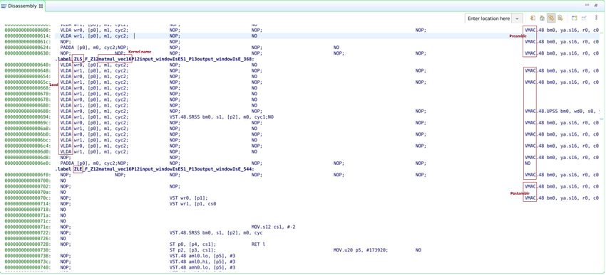
Window vs. Stream in Data Communication......................................................................... 60
          Free Running AI Engine Kernel................................................................................................61
          Run-Time Parameter Specification..........................................................................................62
          AI Engine and PL Kernels Data Communication................................................................... 65
          DDR Memory Access through GMIO...................................................................................... 65

       Chapter 4: Design Analysis and Programming............................................ 66
          Mapping Algorithm onto the AI Engine................................................................................. 66
          Single Kernel Coding Examples............................................................................................... 68
          Multiple Kernels Coding Example: FIR Filter..........................................................................80

       Appendix A: Additional Resources and Legal Notices............................. 88
          Xilinx Resources.........................................................................................................................88
          Documentation Navigator and Design Hubs.........................................................................88
          References..................................................................................................................................88
          Please Read: Important Legal Notices................................................................................... 89

UG1079 (v2020.2) February 4, 2021                                                                                               www.xilinx.com
                                                                                                   Send Feedback
Kernel Coding Best Practices                                                                                                                 4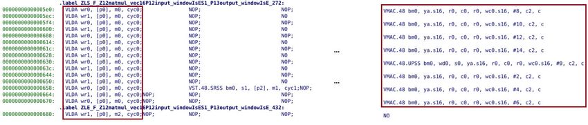
Chapter 1: Overview

                                                                                        Chapter 1

Overview
       The Versal™ AI Core series delivers breakthrough artificial intelligence (AI) inference acceleration
       with AI Engines that deliver over 100x greater compute performance than current server-class of
       CPUs. This series is designed for a breadth of applications, including cloud for dynamic workloads
       and network for massive bandwidth, all while delivering advanced safety and security features. AI
       and data scientists, as well as software and hardware developers, can all take advantage of the
       high compute density to accelerate the performance of any application. Given the AI Engine's
       advanced signal processing compute capability, it is well-suited for highly optimized wireless
       applications such as radio, 5G, backhaul, and other high-performance DSP applications.

       AI Engines are an array of very-long instruction word (VLIW) processors with single instruction
       multiple data (SIMD) vector units that are highly optimized for compute-intensive applications,
       specifically digital signal processing (DSP), 5G wireless applications, and AI technology such as
       machine learning (ML).

       The AI Engine array supports three levels of parallelism:

       • Instruction Level Parallelism (ILP): Through the VLIW architecture allowing multiple
         operations to be executed in a single clock cycle.

       • SIMD: Through vector registers allowing multiple elements (for example, eight) to be
         computed in parallel.

       • Multicore: Through the AI Engine array, allowing up to 400 AI Engines to execute in parallel.

       Instruction-level parallelism includes a scalar operation, up to two moves, two vector reads
       (loads), one vector write (store), and one vector instruction that can be executed—in total, a 7-
       way VLIW instruction per clock cycle. Data-level parallelism is achieved via vector-level
       operations where multiple sets of data can be operated on a per-clock-cycle basis.

       Each AI Engine contains both a vector and scalar processor, dedicated program memory, local 32
       KB data memory, access to local memory in itself and three neighboring AI Engines with the
       direction depending on the row it is in. It also has access to DMA engines and AXI4 interconnect
       switches to communicate via streams to other AI Engines or to the programmable logic (PL) or
       the DMA. Refer to the Versal ACAP AI Engine Architecture Manual (AM009) for specific details on
       the AI Engine array and interfaces.

UG1079 (v2020.2) February 4, 2021                                                          www.xilinx.com
                                                                       Send Feedback
Kernel Coding Best Practices                                                                            5
Chapter 1: Overview

       While most standard C code can be compiled for the AI Engine, the code might need
       restructuring to take full advantage of the parallelism provided by the hardware. The power of an
       AI Engine is in its ability to execute a multiply-accumulate (MAC) operation using two vectors,
       load two vectors for the next operation, store a vector from the previous operation, and
       increment a pointer or execute another scalar operation in each clock cycle. Specialized functions
       called intrinsics allow you to target the AI Engine vector and scalar processor and provides
       implementation of several common vector and scalar functions, so you can focus on the target
       algorithm. In addition to its vector unit, an AI Engine also includes a scalar unit which can be used
       for non-linear functions and data type conversions.

       An AI Engine program consists of a data-flow graph (adaptable data flow graph) specification that
       is written in C++. This specification can be compiled and executed using the AI Engine compiler.
       An adaptive data flow (ADF) graph application consists of nodes and edges where nodes
       represent compute kernel functions, and edges represent data connections. Kernels in the
       application can be compiled to run on the AI Engines, and are the fundamental building blocks of
       an ADF graph specification. ADF graph is a Kahn process network with the AI Engine kernels
       operating in parallel. AI Engine kernels operate on data streams. These kernels consume input
       blocks of data and produce output blocks of data. Kernels can also have static data or run-time
       parameter (RTP) arguments that can be either asynchronous or synchronous.

       The following figure shows the conceptual view of the ADF graph and its interfaces with the
       processing system (PS), programmable logic (PL), and DDR memory. It consists of the following.

       • AI Engine : Each AI Engine is a VLIW processor containing a scalar unit, a vector unit, two load
         units, and a single store unit.

       • AI Engine Kernel: Kernels are written in C/C++ running in an AI Engine.

       • ADF Graph: ADF graph is a network with a single AI Engine kernel or multiple AI Engine
         kernels connected by data streams. It interacts with the PL, global memory, and PS with
         specific constructs like PLIO (port attribute in the graph programming that is used to make
         stream connections to or from the programmable logic), GMIO (port attribute in the graph
         programming that is used to make external memory-mapped connections to or from the
         global memory), and RTP.

UG1079 (v2020.2) February 4, 2021                                                           www.xilinx.com
                                                                        Send Feedback
Kernel Coding Best Practices                                                                             6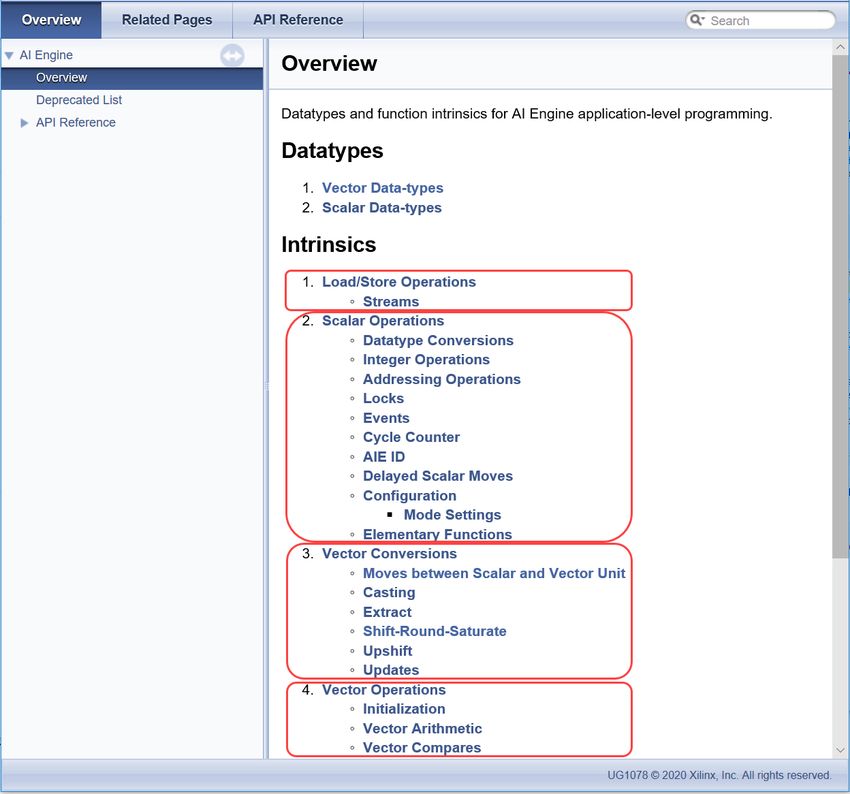
Chapter 1: Overview

                                     Figure 1: Conceptual Overview of the ADF Graph

                         ADF Graph
                                                             Switch                                     Stream                            Switch

                                                              Stream                                                                        Stream

                               AI Engine Tile             DMA                                            AI Engine Tile                  DMA
                                                             MM2S                                                                           S2MM

                                 AI Engine                                                                  AI Engine
                                                          Data Memory                                                                    Data Memory
                                                          Bank 0                                                                         Bank 0
                                                                          Direct Memory access
                                     AI Engine Kernel 1                                                          AI Engine Kernel 1
                                                                        Only valid for neighbor tiles
             Graph
             Control                                      Data Memory                                                                    Data Memory
                                     AI Engine Kernel 2                                                          AI Engine Kernel 2
                                                          Bank 1                                                                         Bank 1

                                                          Data Memory                                                                    Data Memory
                                     …                    Bank 2
                                                                                                                 …                       Bank 2
        PS
                   RTP

                                                          Data Memory                                                                    Data Memory
                                                          Bank 3                                                                         Bank 3

                                                                        PLIO                                          GMIO

                                                                 PL                                                DDR
                                                                                                                                                 X25022-011521

       This document focuses on AI Engine kernel programming and covers some aspects beyond single
       kernel programming, like data communication between kernels, which are essential concepts for
       partitioning the application into multiple kernels to achieve overall system performance.

       For additional details about constructing graph, compiling and simulating graph, and hardware
       flow, refer to the Versal ACAP AI Engine Programming Environment User Guide (UG1076).

Navigating Content by Design Process
       Xilinx® documentation is organized around a set of standard design processes to help you find
       relevant content for your current development task. This document covers the following design
       processes:

       • AI Engine Development: Creating the AI Engine graph and kernels, library use, simulation
         debugging and profiling, and algorithm development. Also includes the integration of the PL
         and AI Engine kernels.

UG1079 (v2020.2) February 4, 2021                                                                                                     www.xilinx.com
                                                                                                  Send Feedback
Kernel Coding Best Practices                                                                                                                       7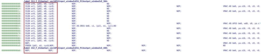
Chapter 1: Overview

AI Engine Architecture Overview
       The AI Engine array consists of a 2D array of AI Engine tiles, where each AI Engine tile contains
       an AI Engine, memory module, and tile interconnect module. An overview of such a 2D array of
       AI Engine tiles is shown in the following figure.

                                          Figure 2: AI Engine Array

        Cascade Stream
        AIE Memory Access
        AXI4 Interconnects

                                                         Memory

                                                                                            Memory

                                                                                                                       Memory
                                                AI                                 AI                        AI
                    Dedicated                 Engine                             Engine                    Engine
                    Interconnect
                    · Non-blocking
                    · Deterministic
                                            Memory

                                                                               Memory

                                                                                                         Memory
                                                       AI                                 AI                         AI
                                                     Engine                             Engine                     Engine
                                                         Memory

                                                                                            Memory

                                                                                                                       Memory
                                                AI                                 AI                        AI
                                              Engine                             Engine                    Engine

                                                                  Local, Distributed Memory
                                                                  · No cache misses
                                                                  · Higher bandwidth                                            X21763-040519

       The memory module is shared between its north, south, east, or west AI Engine neighbors,
       depending on the location of the tile within the array. An AI Engine can access its north, south,
       east, or west, and its own memory module. Those neighboring memory modules are accessed by
       AI Engine through dedicated memory access interfaces, and each of the access can be at most
       256-bit wide. AI Engine can also send or receive cascade streaming data from neighboring AI
       Engine. The cascade stream is one-way stream from left to right or right to left in a horizontal
       manner which wraps around when moving to the next row. The AXI4 interconnect module
       provides streaming connections between AI Engine tiles and provides stream to memory (s2mm)
       or memory to stream (mm2s) connections between streaming interfaces and the memory
       module. In addition, the interconnect modules are also connected to the neighboring
       interconnect module to provide flexible routing capability in a grid like fashion.

UG1079 (v2020.2) February 4, 2021                                                                                 www.xilinx.com
                                                                                        Send Feedback
Kernel Coding Best Practices                                                                                                   8
Chapter 1: Overview

       The following illustration is the architecture of a single AI Engine tile.

                                         Figure 3: AI Engine Tile Details

                                                                                                   Memory Access
                                                                                                   AXI Stream
                                           AI Engine Array                                         AXI MM
                                                                                                   Cascade Stream

                  AXIS West                                                                                 AXIS East

                                                             Load & Store

                                                                                   AXIS North
                   Program            Instruction                                                 S2MM        MEM       MM2S
                   Memory           Fetch & Decode             Address
                                                                                                   DMA         I/F      DMA
                    (16KB)                Unit                Generation
                                                                Units

                                                                            AXIM Switch
                                      Fixed Point        Floating Point
                32b Scalar RISC       512b SIMD           512b SIMD                                          Data

                                                                                                  MEM I/F

                                                                                                                          MEM I/F
                     Unit             Vector Unit         Vector Unit                                       Memory
                                                                                                            (32KB)
                Scalar Register           Vector Register Files
                     Files
                                                                                     AXIS South

                     Stall          Control, Debug,          Accumulator
                    Handler            & Trace               Stream FIFO
                                                                                                            MEM I/F

                                                                                                                                    X24805-111120

       Each AI Engine tile has an AXI4-Stream switch that is a fully programmable 32-bit AXI4-Stream
       crossbar. It supports both circuit-switched and packet-switched streams with back-pressure.
       Through MM2S DMA and S2MM DMA, the AXI4-Stream switch provides stream access from
       and to AI Engine data memory. The switch also contains two 16-deep 33-bit (32-bit data + 1-bit
       TLAST) wide FIFOs, which can be chained to form a 32-deep FIFO by circuit-switching the
       output of one of the FIFOs to the other FIFO’s input.

UG1079 (v2020.2) February 4, 2021                                                                                www.xilinx.com
                                                                            Send Feedback
Kernel Coding Best Practices                                                                                                  9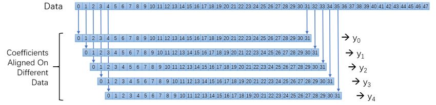
Chapter 1: Overview

       As shown in the following figure, the AI Engine is a highly-optimized processor featuring a single-
       instruction multiple-data (SIMD) and very long instruction word (VLIW) processor containing a
       scalar unit, a vector unit, two load units, a single store unit, and an instruction fetch and decode
       unit. One VLIW instruction can support a maximum of two loads, one store, one scalar operation,
       one fixed-point or floating-point vector operation, and two move instructions.

       The AI Engine also has three address generator units (AGUs) to support multiple addressing
       modes. Two of the AGUs are dedicated for the two load units and one AGU is dedicated for the
       store unit.

                                                 Figure 4: AI Engine

                                                                                   Fixed-Point
               Scalar            Scalar ALU                    Vector              Vector Unit
              Register                                        Register
                Files               Non-linear                  Files            Floating-Point
                                    Functions                                     Vector Unit

                     Scalar Unit                                       Vector Unit

               AGU                    AGU                  AGU            Instruction Fetch
                                                                            & Decode Unit
           Load Unit A          Load Unit B             Store Unit

                       Memory Interface                                   Stream Interface
                                                                                                     X25020-011321

       Additional details about vector processing unit, AI Engine memory, and AI Engine tile interface
       can be found in the following sections.

Scalar Processing Unit
       The following figure shows the sub-components of the scalar unit. The scalar unit is used for
       program control (branch, comparison), scalar math operations, non-linear functions, and data
       type conversions much like a general-purpose processor. Similar to a general-purpose processor,
       generic C/C++ code can be used.

UG1079 (v2020.2) February 4, 2021                                                           www.xilinx.com
                                                                         Send Feedback
Kernel Coding Best Practices                                                                             10
Chapter 1: Overview
Figure 5: Scalar Processing Unit
Scalar
Register Add/
Files CMP MUL MOVE
Subtract
Special
Registers Scalar ALU
Fixed-point Scalar Non-linear Functions
Floating-point Scalar Non-linear Functions
Non-linear Processing
Data-type Conversions
Scalar Unit
X25019-011521
The register files are used to store input and output. There are dedicated registers for pointer
arithmetic, as well as for general-purpose usage and configuration. Special registers include stack
pointers, circular buffers, and zero overhead loops. Two types of scalar elementary non-linear
functions are supported in the AI Engine, fixed-point and floating-point precisions.
Fixed-point, non-linear functions include:
• Sine and cosine
• Absolute value (ABS)
• Count leading zeros (CLZ)
• Comparison to find minimum or maximum (lesser than (LG)/greater than (GT))
• Square root
• Inverse square root and inverse
Floating-point, non-linear functions include:
• Square root
• Inverse square root
• Inverse
• Absolute value (ABS)
UG1079 (v2020.2) February 4, 2021 www.xilinx.com
Send Feedback
Kernel Coding Best Practices 11Chapter 1: Overview
• Comparison to find minimum or maximum (lesser than (LG)/greater than (GT))
The arithmetic logic unit (ALU) in the AI Engine manages the following operations with an issue
rate of one instruction per cycle.
• Integer addition and subtraction of 32 bits. The operation has a one-cycle latency.
• Bit-wise logical operation on 32-bit integer numbers (BAND, BOR, and BXOR). The operation
has a one-cycle latency.
• Integer multiplication: 32 x 32-bit with an output result of 32 bits stored in the R register file.
The operation has a three-cycle latency.
• Shift operation: Both left and right shift are supported. The operation has a one-cycle latency.
Data type conversion can be done using float2fix and fix2float. This conversion can also
support sqrt, inv, and inv_sqrt fixed-point operations.
Scalar Programming
The compiler and scalar unit provide the programmer the ability to use standard ‘C’ data types.
The following table shows standard C data types with their precisions. All types except float and
double support signed and unsigned prefixes.
Table 1: Scalar data types
Data Type Precision Comment
char 8-bit signed
short 16-bit signed
int 32-bit signed Native support
long 64-bit signed
float 32-bit
double 64-bit Emulated using softfloat library. Scalar
proc does not contain FPU.
It is important to remember that control flow statements such as branching are still handled by
the scalar unit even in the presence of vector instructions. This concept is critical to maximizing
the performance of the AI Engine.
UG1079 (v2020.2) February 4, 2021 www.xilinx.com
Send Feedback
Kernel Coding Best Practices 12Chapter 1: Overview
Vector Processing Unit
The vector unit contains a fixed-point unit with 128 8-bit fixed-point multipliers and a floating-
point unit with eight single-precision floating-point multipliers. The vector registers and permute
network are shared between the fixed-point and floating-point multipliers. The peak
performance depends on the size of the data types used by the operands. The following table
provides the number of MAC operations that can be performed by the vector processor per
instruction.
Table 2: AI Engine Vector Precision Support
X Operand Z Operand Output Number of MACs/Clock
8 real 8 real 48 real 128
16 real 8 real 48 real 64
16 real 16 real 48 real 32
16 real 16 complex 48 complex 16
16 complex 16 real 48 complex 16
16 complex 16 complex 48 complex 8
16 real 32 real 48/80 real 16
16 real 32 complex 48/80 complex 8
16 complex 32 real 48/80 complex 8
16 complex 32 complex 48/80 complex 4
32 real 16 real 48/80 real 16
32 real 16 complex 48/80 complex 8
32 complex 16 real 48/80 complex 8
32 complex 16 complex 48/80 complex 4
32 real 32 real 80 real 8
32 real 32 complex 80 complex 4
32 complex 32 real 80 complex 4
32 complex 32 complex 80 complex 2
32 SPFP 32 SPFP 32 SPFP 8
The X operand is 1024 bits wide and the Z operand is 256 bits wide. In terms of component use,
consider the first row in the previous table. The multiplier operands come from the same 1024-
bit and 256-bit input registers but some values are broadcast to multiple multipliers. There are
128 8-bit single multipliers and results are post-added and accumulated into 16 or 8 accumulator
lanes of 48 bits each.
To calculate the maximum performance for a given datapath, it is necessary to multiply the
number of MACs per instruction with the clock frequency of the AI Engine kernel. For example,
with 16-bit input vectors X and Z, the vector processor can achieve 32 MACs per instruction.
Using the clock frequency for the slowest speed grade device results in:
UG1079 (v2020.2) February 4, 2021 www.xilinx.com
Send Feedback
Kernel Coding Best Practices 13Chapter 1: Overview
32 MACs * 1 GHz clock frequency = 32 Giga MAC operations/second
AI Engine Memory
Each AI Engine has 16 KB of program memory, which allows storing 1024 instructions of 128-bit
each. The AI Engine instructions are 128-bit (maximum) wide and support multiple instruction
formats, as well as variable length instructions to reduce the program memory size. Many
instructions outside of the optimized inner loop can use the shorter formats.
Each AI Engine tile has eight data memory banks, where each memory bank (single bank) is a 256
word x 128-bit single-port memory (for a total of 32 KB). Each AI Engine can access the memory
from its north, south, and east or west neighboring tiles, for a total of 128 KB data memory,
including its own data memory. The stack is a subset of the data memory. The default value for
stack size and heap size is 1 KB. This value can be changed using compiler options.
In a logical representation, the 128 KB memory can be viewed as one contiguous 128 KB block
or four 32 KB blocks, and each block can be divided into four odd and four even banks. One even
bank and one odd bank are interleaved to comprise a double bank. AI Engines on the edges of
the AI Engine array have fewer neighbors and correspondingly less memory available.
Each memory port operates in 256-bit/128-bit vector register mode or 32-bit/16-bit/8-bit scalar
register mode. The 256-bit port is created by an even and odd pairing of the memory banks. The
8-bit and 16-bit stores are implemented as read-modify-write instructions. Concurrent operation
of all three ports is supported if each port is accessing a different bank.
Data stored in memory is in little endian format.
RECOMMENDED: It is recommended to access data memory on a 128-bit boundary with vector
operations.
Each AI Engine has a DMA controller that is divided into two separate modules, S2MM to store
stream data to memory (32-bit data) and MM2S to write the contents of the memory to a stream
(32-bit data). Both S2MM and MM2S have two independent data channels.
AI Engine Tile Interface
Data memory interfaces, stream interfaces, and cascade stream interfaces are the primary I/O
interfaces that read and write data for compute to and from the AI Engine.
UG1079 (v2020.2) February 4, 2021 www.xilinx.com
Send Feedback
Kernel Coding Best Practices 14Chapter 1: Overview
• The data memory interface sees one contiguous memory consisting of the data memory
modules in all four directions with a total capacity of 128 KB. The AI Engine has two 256-bit
wide load units and one 256-bit wide store unit. Each load or store can access the data in
128-bit or 256-bit width using 128-bit alignment.
• The AI Engine has two 32-bit input AXI4-Stream interfaces and two 32-bit output AXI4-
Stream interfaces. Each stream is connected to a FIFO on both the input and output side,
allowing the AI Engine to have a 128-bit access every four clock cycles or 32-bit wide access
per cycle on a stream.
• The 384-bit accumulator data from one AI Engine can be forwarded to another by using the
dedicated cascade stream interfaces to form a chain. There is a small, two deep, 384-bit wide
FIFO on both the input and output streams that allows storing up to four values between AI
Engines. In each cycle, 384-bits can be received and sent by the chained AI Engines. The
cascade stream chain provides a relative tight coupling of multiple kernels operating at the
same throughput.
When programming for the AI Engine, it is important to note that each AI Engine has the
capability to access two 32-bit AXI4-Stream inputs, two 32-bit AXI4-Stream outputs, one 384-bit
cascade stream input, one 384-bit cascade stream output, two 256-bit data loads, and one 256-
bit data store. However, due to the length of the instruction, not all of these operations can be
performed during the same cycle.
Tools
Vitis Integrated Design Environment
The Vitis™ integrated design environment (IDE) can be used to target system programming of
Xilinx devices including, Versal devices. It supports development of single and multiple AI Engine
kernel applications. The following features are available in the tool.
• An optimizing C/C++ compiler that compiles the kernels and graph code making all of the
necessary connections, placements, and checks to ensure proper functioning on the device.
• A cycle accurate simulator, accelerated functional simulator, and profiling tools.
• A powerful debugging environment that works in both simulation and hardware
environments. Various views, such as, variables view, disassembly view, memory view, register
view, and pipeline view are available.
Vitis Command Line Tools
Command line tools are available to build, simulate, and generate output files and reports.
• The AI Engine compiler compiles kernels and graph code into ELF files that are run on the AI
Engine processors.
UG1079 (v2020.2) February 4, 2021 www.xilinx.com
Send Feedback
Kernel Coding Best Practices 15Chapter 1: Overview
• The AI Engine simulator and x86simulator are tools for cycle approximate simulation and
functional simulation respectively.
• The cross compiler for Arm® Core is provided for PS code compilation.
• The Vitis compiler is the system compilation and linking tool for integrating whole system
together.
• The Vitis Analyzer IDE is available for report viewing and analysis of the output files and
reports generated by the command line tools.
The Versal ACAP AI Engine Programming Environment User Guide (UG1076) contains a wealth of
information on the design flow and tools' usage.
UG1079 (v2020.2) February 4, 2021 www.xilinx.com
Send Feedback
Kernel Coding Best Practices 16Chapter 2: Single Kernel Programming
Chapter 2
Single Kernel Programming
An AI Engine kernel is a C/C++ program which is written using native C/C++ language and
specialized intrinsic functions that target the VLIW scalar and vector processors. The AI Engine
kernel code is compiled using the AI Engine compiler (aiecompiler) that is included in the Vitis™
core development kit. The AI Engine compiler compiles the kernels to produce ELF files that are
run on the AI Engine processors.
For more information on intrinsic functions, see the Versal ACAP AI Engine Intrinsics
Documentation (UG1078). AI Engine compiler and simulator are covered in the first few sections
of this chapter.
AI Engine supports specialized data types and intrinsic functions for vector programming. By
restructuring the scalar application code with these intrinsic functions and vector data types as
needed, you can implement the vectorized application code. The AI Engine compiler takes care of
mapping intrinsic functions to operations, vector or scalar register allocation and data movement,
automatic scheduling, and generation of microcode that is efficiently packed in VLIW
instructions.
The following sections introduce the data types supported and registers available for use by the
AI Engine kernel. In addition, the vector intrinsic functions that initialize, load, and store, as well
as operate on the vector registers using the appropriate data types are also described.
To achieve the highest performance on the AI Engine, the primary goal of single kernel
programming is to ensure that the usage of the vector processor approaches its theoretical
maximum. Vectorization of the algorithm is important, but managing the vector registers,
memory access, and software pipelining are also required. The programmer must strive to make
the data for the new operation available while the current operation is executing because the
vector processor is capable of an operation every clock cycle. Optimizations using software
pipelining in loops is available using pragmas. For instance, when the inner loop has sequential or
loop carried dependencies it might be possible to unroll an outer loop and compute multiple
values in parallel. The following sections go over these concepts as well.
Intrinsics
For intrinsic function documentation, see the Versal ACAP AI Engine Intrinsics Documentation
(UG1078).
UG1079 (v2020.2) February 4, 2021 www.xilinx.com
Send Feedback
Kernel Coding Best Practices 17Chapter 2: Single Kernel Programming
The intrinsic function documentation is organized by the different types of operations and data
types. The function calls at the highest level are organized in the documentation as follows:
• Load /Store Operations: About pointer dereferencing and pointer arithmetic, as well as
operations on streams.
• Scalar Operations: Operations on integer and floating point scalar values, configuration,
conversions, addressing, locks and events.
• Vector Conversions: Handling of vectors with different sizes and precisions.
• Vector Operations: Arithmetic operations performed on vectors.
• Application Specific Intrinsics: Intrinsics assisting in the implementation of a specific
application.
UG1079 (v2020.2) February 4, 2021 www.xilinx.com
Send Feedback
Kernel Coding Best Practices 18Chapter 2: Single Kernel Programming
Figure 6: Intrinsic Function Documentation
It is also available through the Vitis™ IDE.
UG1079 (v2020.2) February 4, 2021 www.xilinx.com
Send Feedback
Kernel Coding Best Practices 19Chapter 2: Single Kernel Programming
Figure 7: Intrinsics Documentation through the Vitis IDE
Kernel Pragmas
The AI Engine compiler supports dedicated directives for efficient loop scheduling. Additional
pragmas for reducing memory dependencies and removing function hierarchy while further
optimizing kernel performance is also included. Examples of the use of those pragmas can be
found in this document.
The Chess Compiler User Manual has a list of all the pragmas and functions used in kernel
coding. This manual can be found in the AI Engine lounge.
Kernel Compiler
The AI Engine compiler is used to compile AI Engine kernel code. Compiling an AI Engine Graph
Application in the AI Engine Documentation flow of the Vitis Unified Software Platform
Documentation (UG1416) describes in detail the AI Engine compiler usage, options available,
input files that can be passed in, and expected output.
UG1079 (v2020.2) February 4, 2021 www.xilinx.com
Send Feedback
Kernel Coding Best Practices 20Chapter 2: Single Kernel Programming
Kernel Simulation
To simulate an AI Engine kernel you need to write an AI Engine graph application that consists of
a data-flow graph specification which is written in C++. This graph will contain just the AI Engine
kernel, with test bench data being provided as input(s) to the kernel. The data output(s) from the
kernel can be captured as the simulation output and compared against golden data. This
specification can be compiled and executed using the AI Engine compiler. The application can be
simulated using the AI Engine simulator. For additional details on the simulator, see Simulating an
AI Engine Graph Application in the AI Engine Documentation flow of the Vitis Unified Software
Platform Documentation (UG1416).
Kernel Inputs and Outputs
AI Engine kernels operate on either streams or blocks of data. AI Engine kernels operate on data
of specific types, for example, int32 and cint32. A block of data used by a kernel is called a
window of data. Kernels consume input stream or window of data and produce output stream or
window of data. Kernels access data streams in a sample-by-sample fashion. For additional
details on the window and stream APIs, see Window and Streaming Data API in the AI Engine
Documentation flow of the Vitis Unified Software Platform Documentation (UG1416).
AI Engine kernels can also have RTP ports to be updated or read by PS. For more information
about RTP, see Run-Time Graph Control API in the AI Engine Documentation flow of the Vitis
Unified Software Platform Documentation (UG1416).
Introduction to Scalar and Vector
Programming
This section provides an overview of the key elements of kernel programming for scalar and
vector processing elements. The details of each element and optimization skills will be seen in
following sections.
The following example uses only the scalar engine. It demonstrates a for loop iterating through
512 int32 elements. Each loop iteration performs a single multiply of int32 a and int32 b storing
the result in c and writing it to an output window. The scalar_mul kernel operates on two input
blocks (window) of data input_window_int32 and produces an output window of data
output_window_int32.
UG1079 (v2020.2) February 4, 2021 www.xilinx.com
Send Feedback
Kernel Coding Best Practices 21Chapter 2: Single Kernel Programming
The APIs window_readincr and window_writeincr are used to read and write to the
circular buffers outside the kernel. For additional details on the window APIs, see Window and
Streaming Data API in the AI Engine Documentation flow of the Vitis Unified Software Platform
Documentation (UG1416).
void scalar_mul(input_window_int32* data1,
input_window_int32* data2,
output_window_int32* out){
for(int i=0;iChapter 2: Single Kernel Programming
The scalar version of this example function takes 1055 cycles while the vectorized version takes
only 99 cycles. As you can see there is more than 10 times speedup for vectorized version of the
kernel. Vector processing itself would give 8x the throughput for int32 multiplication but has a
higher latency and would not get 8x the throughput overall. However, with the loop
optimizations done, it can get close to 10x. The sections that follow describe in detail the various
data types that can be used, registers available, and also the kinds of optimizations that can be
achieved on the AI Engine using concepts like software pipelining in loops and keywords like
__restrict.
Related Information
Software Pipelining of Loops
Restrict Keyword
AI Engine Data Types
The AI Engine scalar unit supports signed and unsigned integers in 8, 16, and 32-bit widths, along
with some single-precision floating-point for specific operations.
The AI Engine vector unit supports integers and complex integers in 8, 16, and 32-bit widths,
along with real and complex single-precision floating-point numbers. It also supports accumulator
vector data types, with 48 and 80-bit wide elements. Intrinsic functions such as absolute value,
addition, subtraction, comparison, multiplication, and MAC operate using these vector data
types. Vector data types are named using a convention that includes the number of elements,
real or complex, vector type or accumulator type, and bit width as follows:
v{NumLanes}[c]{[u]int|float|acc}{SizeofElement}
Optional specifications include:
• NumLanes: Denotes the number of elements in the vector which can be 2, 4, 8, 16, 32, 64, or
128.
• c: Denotes complex data with real and imaginary parts packed together.
• int: denotes integer vector data values.
• float: Denotes single precision floating point values.
Note: There are no accumulator registers for floating-point vectors.
• acc: Denotes accumulator vector data values.
• u: Denotes unsigned. Unsigned only exists for int8 vectors.
• SizeofElement: Denotes the size of the vector data type element.
UG1079 (v2020.2) February 4, 2021 www.xilinx.com
Send Feedback
Kernel Coding Best Practices 23Chapter 2: Single Kernel Programming
• 1024-bit integer vector types are vectors of 8-bit, 16-bit, or 32-bit vector elements. These
vectors have 16, 32, 64, or 128 lanes.
• 512-bit integer vector types are vectors of 8-bit, 16-bit, 32-bit, or 64-bit vector elements.
These vectors have 4, 8, 16, 32, or 64 lanes.
• 256-bit integer vector types are vectors of 8-bit, 16-bit, 32-bit, 64-bit, or 128-bit vector
elements. These vectors have 1, 2, 4, 8, 16, or 32 lanes.
• 128-bit integer vector types are vectors of 8-bit, 16-bit, or 32-bit vector elements. These
vectors have 2, 4, 8, or 16 lanes.
• Accumulator data types are vectors of 80-bit or 48-bit elements These vectors have 2, 4, 8,
or 16 lanes.
The total data-width of the vector data-types can be 128-bit, 256-bit, 512-bit, or 1024-bit. The
total data-width of the accumulator data-types can be 320/384-bit or 640/768-bit.
For example, v16int32 is a sixteen element vector of integers with 32 bits. Each element of the
vector is referred to as a lane. Using the smallest bit width necessary can improve performance
by making good use of registers.
Figure 8: v16int32
32b 32b 32b 32b 32b 32b 32b 32b 32b 32b 32b 32b 32b 32b 32b 32b
0 1 2 3 4 5 6 7 8 9 10 11 12 13 14 15
X25021-011321
Vector Registers
All vector intrinsic functions require the operands to be present in the AI Engine vector registers.
The following table shows the set of vector registers and how smaller registers are combined to
form large registers.
UG1079 (v2020.2) February 4, 2021 www.xilinx.com
Send Feedback
Kernel Coding Best Practices 24Chapter 2: Single Kernel Programming
Table 3: Vector Registers
128-bit 256-bit 512-bit 1024-bit
vrl0
wr0
vrh0
xa N/A
vrl1
wr1
vrh1
ya
vrl2
wr2
vrh2
xb yd (msbs)
vrl3
wr3
vrh3
vcl0
wc0
vch0
xc N/A N/A
vcl1
wc1
vch1
vdl0
wd0
vdh0
xd N/A yd (lsbs)
vdl1
wd1
vdh1
The underlying basic hardware registers are 128-bit wide and prefixed with the letter v. Two v
registers can be grouped to form a 256-bit register prefixed with w. wr, wc, and wd registers are
grouped in pairs to form 512-bit registers (xa, xb, xc, and xd). xa and xb form the 1024-bit wide
ya register, while xd and xb form the 1024-bit wide yd register. This means the xb register is
shared between ya and yd registers. xb contains the most significant bits (MSBs) for both ya and
yd registers.
The vector register name can be used with the chess_storage directive to force vector data
to be stored in a particular vector register. For example:
v8int32 chess_storage(wr0) bufA;
v8int32 chess_storage(WR) bufB;
When upper case is used in the chess_storage directive, it means register files (for example,
any of the four wr registers), whereas lower case in the directive means just a particular register
(for example, wr0 in the previous code example) will be chosen.
Vector registers are a valuable resource. If the compiler runs out of available vector registers
during code generation, then it generates code to spill the register contents into local memory
and read the contents back when needed. This consumes extra clock cycles.
The name of the vector register used by the kernel during its execution is shown for vector load/
store and other vector-based instructions in the kernel microcode. This microcode is available in
the disassembly view in Vitis IDE. For additional details on Vitis IDE usage, see Using Vitis IDE
and Reports.
UG1079 (v2020.2) February 4, 2021 www.xilinx.com
Send Feedback
Kernel Coding Best Practices 25Chapter 2: Single Kernel Programming
Many intrinsic functions only accept specific vector data types but sometimes not all values from
the vector are required. For example, certain intrinsic functions only accept 512-bit vectors. If
the kernel code has smaller sized data, one technique that can help is to use the concat()
intrinsic to concatenate this smaller sized data with an undefined vector (a vector with its type
defined, but not initialized).
For example, the lmul8 intrinsic only accepts a v16int32 or v32int32 vector for its xbuff
parameter. The intrinsic prototype is:
v8acc80 lmul8 ( v16int32 xbuff,
int xstart,
unsigned int xoffsets,
v8int32 zbuff,
int zstart,
unsigned int zoffsets
)
The xbuff parameter expects a 16 element vector (v16int32). In the following example, there is
an eight element vector (v8int32) rva. The concat() intrinsic is used to upgrade it to a 16
element vector. After concatenation, the lower half of the 16 element vector has the contents of
rva. The upper half of the 16 element vector is uninitialized due to concatenation with the
undefined v8int32 vector.
int32 a[8] = {1, 2, 3, 4, 5, 6, 7, 8};
v8int32 rva = *((v8int32*)a);
acc = lmul8(concat(rva,undef_v8int32()),0,0x76543210,rvb,0,0x76543210);
For more information about how vector-based intrinsic functions work, refer to Vector Register
Lane Permutations.
Accumulator Registers
The accumulation registers are 384 bits wide and can be viewed as eight vector lanes of 48 bits
each. The idea is to have 32-bit multiplication results and accumulate over those results without
bit overflows. The 16 guard bits allow up to 216 accumulations. The output of fixed-point vector
MAC and MUL intrinsic functions is stored in the accumulator registers. The following table
shows the set of accumulator registers and how smaller registers are combined to form large
registers.
Table 4: Accumulator Registers
384-bit 768-bit
aml0
bm0
amh0
UG1079 (v2020.2) February 4, 2021 www.xilinx.com
Send Feedback
Kernel Coding Best Practices 26Chapter 2: Single Kernel Programming
Table 4: Accumulator Registers (cont'd)
384-bit 768-bit
aml1
bm1
amh1
aml2
bm2
amh2
aml3
bm3
amh3
The accumulator registers are prefixed with the letters 'am'. Two of them are aliased to form a
768-bit register that is prefixed with 'bm'.
The shift-round-saturate srs() intrinsic is used to move a value from an accumulator register to
a vector register with any required shifting and rounding.
v8int32 res = srs(acc, 8); // shift right 8 bits, from accumulator register
to vector register
The upshift ups() intrinsic is used to move a value from an vector register to an accumulator
register with upshifting:
v8acc48 acc = ups(v, 8); //shift left 8 bits, from vector register to
accumulator register
The set_rnd() and set_sat() instrinsics are used to set the rounding and saturation mode
of the accumulation result, while clr_rnd() and clr_sat() intrinsics are used to clear the
rounding and saturation mode, that is to truncate the accumulation result.
Note that only when operations are going through the shift-round-saturate data path, the
shifting, rounding, or saturation mode will be effective. Some intrinsics only use the vector pre-
adder operations, where there will be no shifting, rounding, or saturation mode for configuration.
Such operations are adds, subs, abs, vector compares, or vector selections/shuffles. It is possible
to choose MAC intrinsics instead to do subtraction with shifting, rounding, or saturation mode
configuration. The following code performs subtraction between va and vb with mul instead of
sub intrinsics.
v16cint16 va, vb;
int32 zbuff[8]={1,1,1,1,1,1,1,1};
v8int32 coeff=*(v8int32*)zbuff;
v8acc48 acc = mul8_antisym(va, 0, 0x76543210, vb, 0, false, coeff, 0 ,
0x76543210);
v8int32 res = srs(acc,0);
Floating-point intrinsic functions do not have separate accumulation registers and instead return
their results in a vector register.
UG1079 (v2020.2) February 4, 2021 www.xilinx.com
Send Feedback
Kernel Coding Best Practices 27Chapter 2: Single Kernel Programming
Casting and Datatype Conversion
Casting intrinsic functions (as_[Type]()) allow casting between vector types or scalar types of
the same size. The casting can work on accumulator vector types too. Generally, using the
smallest data type possible will reduce register spillage and improve performance. For example, if
a 48-bit accumulator (acc48) can meet the design requirements then it is preferable to use that
instead of a larger 80-bit accumulator (acc80).
Note: The acc80 vector data type occupies two neighboring 48-bit lanes.
Standard C casts can be also used and works identically in almost all cases as shown in the
following example.
v8int16 iv;
v4cint16 cv=as_v4cint16(iv);
v4cint16 cv2=*(v4cint16*)&iv;
v8acc80 cas_iv;
v8cacc48 cas_cv=as_v8cacc48(cas_iv);
There is hardware support built-in for floating-point to fixed-point (float2fix()) and fixed-
point to floating-point (fix2float()) conversions. For example, the fixed-point square root,
inverse square root, and inverse are implemented with floating point precision and the
fix2float() and float2fix() conversions are used before and after the function. The
scalar engine is used in this example because the square root and inverse functions are not
vectorizable. This can be verified by looking at the function prototype's input data types:
float _sqrtf(float a) //scalar float operation
int sqrt(int a,...) //scalar integer operation
Note that the input data types are scalar types (int) and not vector types (vint).
The conversion functions (fix2float, float2fix) can be handled by either the vector or
scalar engines depending on the function called. Note the difference in data return type and data
argument types:
float fix2float(int n,...) //Uses the scalar engine
v8float fix2float(v8int32 ivec,...) //Uses the vector engine
Note: For float2fix, there are two types of implementations, float2fix_safe (default) and
float2fix_fast with the float2fix_safe implementation offering a more strict data type check.
You can define the macro FLOAT2FIX_FAST to make float2fix choose the float2fix_fast
implementation.
UG1079 (v2020.2) February 4, 2021 www.xilinx.com
Send Feedback
Kernel Coding Best Practices 28Chapter 2: Single Kernel Programming
Vector Initialization, Load, and Store
Vector registers can be initialized, loaded, and saved in a variety of ways. For optimal
performance, it is critical that the local memory that is used to load or save the vector registers
be aligned on 16-byte boundaries.
Alignment
The alignas standard C specifier can be used to ensure proper alignment of local memory. In
the following example, the reals is aligned to 16 byte boundary.
alignas(16) const int32 reals[8] =
{32767, 23170, 0, -23170, -32768, -23170, 0, 23170};
//align to 16 bytes boundary, equivalent to "alignas(v4int32)"
Initialization
The following functions can be used to initialize vector registers as undefined, all 0’s, with data
from local memory, or with part of the values set from another register and the remaining part
are undefined. Initialization using the undef_type() initializer ensures that the compiler can
optimize regardless of the undefined parts of the value.
v8int32 v;
v8int32 uv = undef_v8int32(); //undefined
v8int32 nv = null_v8int32(); //all 0's
v8int32 iv = *(v8int32 *) reals; //re-interpret "reals" as "v8int32"
pointer and load value from it
v16int32 sv = xset_w(0, iv); //create a new 512-bit vector with lower 256-
bit set with "iv"
In the previous example, vector set intrinsic functions [T]set_[R] allow creating a vector
where only one part is initialized and the other parts are undefined. Here [T] indicates the target
vector register to be set, w for W register (256-bit), x for X register (512-bit), and y for Y register
(1024-bit). [R] indicates where the source value comes from, v for V register (128-bit), w for W
register (256-bit), and x for X register (512-bit). Note that [R] width is smaller than [T] width. The
valid vector set intrinsic functions are, wset_v, xset_v, xset_w, yset_v, yset_w, and
yset_x.
UG1079 (v2020.2) February 4, 2021 www.xilinx.com
Send Feedback
Kernel Coding Best Practices 29Chapter 2: Single Kernel Programming
Load and Store
Load and Store From Vector Registers
The compiler supports standard pointer de-referencing and pointer arithmetic for vectors. Post
increment of the pointer is the most efficient form for scheduling. No special intrinsic functions
are needed to load vector registers.
v8int32 * ptr_coeff_buffer = (v8int32 *)ptr_kernel_coeff;
v8int32 kernel_vec0 = *ptr_coeff_buffer++; // 1st 8 values (0 .. 7)
v8int32 kernel_vec1 = *ptr_coeff_buffer; // 2nd 8 values (8 .. 15)
Load and Store From Memory
AI Engine APIs provide access methods to read and write data from data memory, streaming data
ports, and cascade streaming ports which can be used by AI Engine kernels. For additional details
on the window and stream APIs, see Window and Streaming Data API in the AI Engine
Documentation flow of the Vitis Unified Software Platform Documentation (UG1416). In the
following example, the window readincr (window_readincr_v8(din)) API is used to read
a window of complex int16 data into the data vector. Similarly, readincr_v8(cin) is used to
read a sample of int16 data from the cin stream. writeincr_v4 (cas_out, v) is used to
write data to a cascade stream output.
void func(input_window_cint16 *din,
input_stream_int16 *cin,
output_stream_cacc48 *cas_out){
v8cint16 data=window_readincr_v8(din);
v8int16 coef=readincr_v8(cin);
v4cacc48 v;
…
writeincr_v4(cas_out, v);
}
Load and Store Using Pointers
It is mandatory to use the window API in the kernel function prototype as inputs and outputs.
However, in the kernel code, it is possible to use a direct pointer reference to read/write data.
void func(input_window_int16 *w_input,
output_window_cint16 *w_output){
.....
v16int16 *ptr_in = (v16int16 *)w_input->ptr;
v8cint16 *ptr_out = (v8cint16 *)w_output->ptr;
......
}
The window structure is responsible for managing buffer locks tracking buffer type (ping/pong)
and this can add to the cycle count. This is especially true when load/store are out-of-order
(scatter-gather). Using pointers may help reduce the cycle count required for load and store.
UG1079 (v2020.2) February 4, 2021 www.xilinx.com
Send Feedback
Kernel Coding Best Practices 30Chapter 2: Single Kernel Programming
Note: If using pointers to load and store data, it is the designer’s responsibility to avoid out-of-bound
memory access.
Load and Store Using Streams
Vector data can also be loaded from or stored in streams as shown in the following example.
void func(input_stream_int32 *s0, input_stream_int32 *s1, …){
for(…){
data0=readincr(s0);
data1=readincr(s1);
…
}
}
For more information about window and streaming data API usage, see Window and Streaming
Data API in the AI Engine Documentation flow of the Vitis Unified Software Platform
Documentation (UG1416).
Update, Extract, and Shift
To update portions of vector registers, the upd_v(), upd_w(), and upd_x() intrinsic functions
are provided for 128-bit (v), 256-bit (w), and 512-bit (x) updates.
Note: The updates overwrite a portion of the larger vector with the new data while keeping the other part
of the vector alive. This alive state of the larger vector persists through multiple updates. If too many
vectors are kept unnecessarily alive, register spillage can occur and impact performance.
Similarly, ext_v(), ext_w(), and ext_x() intrinsic functions are provided to extract portions
of the vector.
To update or extract individual elements, the upd_elem() and ext_elem() intrinsic functions
are provided. These must be used when loading or storing values that are not in contiguous
memory locations and require multiple clock cycles to load or store a vector. In the following
example, the 0th element of vector v1 is updated with the value of a - which is 100.
int a = 100;
v4int32 v1 = upd_elem(undef_v4int32(), 0, a);
Another important use is to move data to the scalar unit and do an inverse or sqrt. In the
following example, the 0th element of vector vf is extracted and stored in the scalar variable f.
v4float vf;
float f=ext_elem(vf,0);
float i_f=invsqrt(f);
The shft_elem() intrinsic function can be used to update a vector by inserting a new element
at the beginning of a vector and shifting the other elements by one.
UG1079 (v2020.2) February 4, 2021 www.xilinx.com
Send Feedback
Kernel Coding Best Practices 31Chapter 2: Single Kernel Programming
Vector Register Lane Permutations
The AI Engine fixed point vector units datapath consists of the following three separate and
largely independently usable paths:
• Main MAC datapath
• Shift-round-saturate path
• Upshift path
The main multiplication path reads values from vector registers, permutes them in a user
controllable fashion, performs optional pre-adding, multiplies them, and after some post-adding
accumulates them to the previous value of the accumulator register.
While the main datapath stores to the accumulator, the shift-round-saturate path reads from the
accumulator registers and stores to the vector registers or the data memory. In parallel to the
main datapath runs the upshift path. It does not perform any multiplications but simply reads
vectors, upshifts them and feeds the result into the accumulators. For details on the Fixed point
and Floating point data paths refer to Versal ACAP AI Engine Architecture Manual (AM009). Details
on the intrinsic functions that can be used to exercise these data paths can be found in the Versal
ACAP AI Engine Intrinsics Documentation (UG1078).
As shown in the following figure, the basic functionality of MAC data path consists of vector
multiply and accumulate operations between data from the X and Z buffers. Other parameters
and options allow flexible data selection within the vectors and number of output lanes and
optional features allow different input data sizes and pre-adding. There is an additional input
buffer, the Y buffer, whose values can be pre-added with those from the X buffer before the
multiplication occurs. The result from the intrinsic is added to an accumulator.
UG1079 (v2020.2) February 4, 2021 www.xilinx.com
Send Feedback
Kernel Coding Best Practices 32Chapter 2: Single Kernel Programming
Figure 9: Functional Overview of the MAC Data Path
VC Registers
Z Post-
Load Permute
Buffer add
VCs
e.g., Coefficients Pre-add
Advanced
Vector Acc x +
VA & VB Registers MAC VAs &
+
VBs
X and Y Accumulation
Load Vector
Buffer Decoder
AM Register
e.g., Filter Delay Line Configuration
Configuration from Intrinsic
Type and Parameters
X25023-011521
The operation can be described using lanes and columns. The number of lanes corresponds to the
number of output values that will be generated from the intrinsic call. The number of columns is
the number of multiplications that will be performed per output lane, with each of the
multiplication results being added together. For example:
acc0 += z00*(x00+y00) + z01*(x01+y01) + z02*(x02+y02) + z03*(x03+y03)
acc1 += z10*(x10+y10) + z11*(x11+y11) + z12*(x12+y12) + z13*(x13+y13)
acc2 += z20*(x20+y20) + z21*(x21+y21) + z22*(x22+y22) + z23*(x23+y23)
acc3 += z30*(x30+y30) + z31*(x31+y31) + z32*(x32+y32) + z33*(x33+y33)
In this case, four outputs are being generated, so there are four lanes and four columns for each
of the outputs with pre-addition from the X and Y buffers.
The parameters of the intrinsics allow for flexible data selection from the different input buffers
for each lane and column, all following the same pattern of parameters. The following section
introduces the data selection (or data permute) schemes with detailed examples that include
shuffle and select intrinsics. Details around the mac intrinsic and its variants are also
discussed in the following sections.
Data Selection
AI Engine intrinsic functions support various types of data selection. The details around the
shuffle and select intrinsic are as follows.
UG1079 (v2020.2) February 4, 2021 www.xilinx.com
Send Feedback
Kernel Coding Best Practices 33You can also read