MVI46-MNET SLC Platform Modbus TCP/IP Interface Module - USER MANUAL
←
→
Page content transcription
If your browser does not render page correctly, please read the page content below

MVI46-MNET
       SLC Platform
       Modbus TCP/IP Interface Module

                                    June 22, 2009

USER MANUAL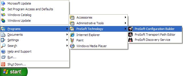
MVI (Multi Vendor Interface) Modules
WARNING - EXPLOSION HAZARD - DO NOT DISCONNECT EQUIPMENT UNLESS POWER HAS BEEN
SWITCHED OFF OR THE AREA IS KNOWN TO BE NON-HAZARDOUS.
AVERTISSEMENT - RISQUE D'EXPLOSION - AVANT DE DÉCONNECTER L'EQUIPMENT, COUPER LE
COURANT OU S'ASSURER QUE L'EMPLACEMENT EST DÉSIGNÉ NON DANGEREUX.

CL I Div 2 GPs A, B, C, D
Temp Code T5
II 3 G
Ex nA IIC T5 X
0° C

Markings
ANSI / ISA                ISA 12.12.01 Class I Division 2, GPs A, B, C, D
CSA/cUL                   C22.2 No. 213-1987
CSA CB Certified          IEC61010
ATEX                      EN60079-0 Category 3, Zone 2
                          EN60079-15

243333

Warning: This module is not hot-swappable! Always remove power from the rack before inserting or removing this
module, or damage may result to the module, the processor, or other connected devices.

Battery Life Advisory
All modules in the MVI series use a rechargeable Lithium Vanadium Pentoxide battery to backup the 512K SRAM
memory, real-time clock, and CMOS. The battery should last for the life of the module.
The module must be powered for approximately twenty hours before it becomes fully charged. After it is fully charged,
the battery provides backup power for the CMOS setup and configuration data, the real-time clock, and the 512K
SRAM memory for approximately 21 days.
Before you remove a module from its power source, ensure that the battery within the module is fully charged. A fully
charged battery will hold the BIOS settings (after being removed from its power source) for a limited number of days.
When the battery is fully discharged, the module will revert to the default BIOS settings.

Note: The battery is not user replaceable.

Your Feedback Please
We always want you to feel that you made the right decision to use our products. If you have suggestions, comments,
compliments or complaints about the product, documentation or support, please write or call us.
ProSoft Technology
5201 Truxtun Ave., 3rd Floor
Bakersfield, CA 93309
+1 (661) 716-5100
+1 (661) 716-5101 (Fax)
www.prosoft-technology.com
Copyright © ProSoft Technology, Inc. 2009. All Rights Reserved.
MVI46-MNET User Manual
June 22, 2009
ProSoft Technology ®, ProLinx ®, inRAx ®, ProTalk®, and RadioLinx ® are Registered Trademarks of ProSoft
Technology, Inc. All other brand or product names are or may be trademarks of, and are used to identify products
and services of, their respective owners.
ProSoft Technology® Product Documentation In an effort to conserve paper, ProSoft Technology no longer includes printed manuals with our product shipments. User Manuals, Datasheets, Sample Ladder Files, and Configuration Files are provided on the enclosed CD, and are available at no charge from our web site: www.prosoft-technology.com Printed documentation is available for purchase. Contact ProSoft Technology for pricing and availability. Asia Pacific: +603.7724.2080 Europe, Middle East, Africa: +33 (0) 5.3436.87.20 Latin America: +1.281.298.9109 North America: +1.661.716.5100
Contents                                                                                                                          MVI46-MNET ♦ SLC Platform
User Manual                                                                                                                     Modbus TCP/IP Interface Module

       Contents
           MVI (Multi Vendor Interface) Modules ................................................................................................ 2
           Important Installation Instructions ....................................................................................................... 2
           Warnings ............................................................................................................................................. 2
           Battery Life Advisory ........................................................................................................................... 3
           Your Feedback Please........................................................................................................................ 3
           ProSoft Technology® Product Documentation ...................................................................................4

       Guide to the MVI46-MNET User Manual                                                                                                                      7

       1         Start Here                                                                                                                                     9
           1.1                     System Requirements - MVI46 PCB.........................................................................9
           1.2                     Package Contents ...................................................................................................10
           1.3                     Install ProSoft Configuration Builder Software ........................................................11
           1.4                     Setting Jumpers ......................................................................................................12
           1.5                     Install the Module in the Rack .................................................................................12
           1.6                     Connect your PC to the Processor..........................................................................14
           1.7                     Download the Sample Program to the Processor...................................................15
           1.8                     Connect your PC to the Module ..............................................................................18

       2         Configuring the MVI46-MNET Module                                                                                                            19
           2.1                     ProSoft Configuration Builder..................................................................................19
           2.2                     Download the Project to the Module .......................................................................36

       3         Ladder Logic                                                                                                                                 37
           3.1                     Module Data ............................................................................................................37
           3.2                     Adding the Module to an Existing Project ...............................................................38

       4         Diagnostics and Troubleshooting                                                                                                              41
           4.1                     Reading Status Data from the Module ....................................................................41
           4.2                     LED Status Indicators..............................................................................................51

       5         Reference                                                                                                                                    55
           5.1                     Product Specifications.............................................................................................55
           5.2                     Functional Overview................................................................................................57
           5.3                     Cable Connections ..................................................................................................67
           5.4                     MVI46-MNET Status Data Definition.......................................................................71
           5.5                     Modbus Protocol Specification................................................................................73

       6         Support, Service & Warranty                                                                                                                  83
           6.1                     How to Contact Us: Technical Support ...................................................................83

ProSoft Technology, Inc.                                                                                                                               Page 5 of 93
June 22, 2009
MVI46-MNET ♦ SLC Platform Contents
Modbus TCP/IP Interface Module User Manual
6.2 Return Material Authorization (RMA) Policies and Conditions ............................... 84
6.3 LIMITED WARRANTY ............................................................................................ 85
Index 91
Page 6 of 93 ProSoft Technology, Inc.
June 22, 2009Start Here MVI46-MNET ♦ SLC Platform
User Manual Modbus TCP/IP Interface Module
Guide to the MVI46-MNET User Manual
Function Section to Read Details
Introduction → Start Here (page 9) This Section introduces the customer to the
(Must Do) module. Included are: package contents,
system requirements, hardware installation, and
basic configuration.
Verify Communication, → Verifying This section describes how to verify
Diagnostic and Communication communications with the network. Diagnostic
Troubleshooting (page 51) and Troubleshooting procedures.
Diagnostics and
Troubleshooting
(page 41)
Reference → Reference (page 55) These sections contain general references
Product Specifications Functional Overview associated with this product, Specifications, and
(page 57) the Functional Overview.
Functional Overview
Product
Specifications (page
55)
Support, Service, and → Support, Service This section contains Support, Service and
Warranty and Warranty (page Warranty information.
Index 83) Index of chapters.
ProSoft Technology, Inc. Page 7 of 93
June 22, 2009MVI46-MNET ♦ SLC Platform Start Here
Modbus TCP/IP Interface Module User Manual
Page 8 of 93 ProSoft Technology, Inc.
June 22, 2009Start Here MVI46-MNET ♦ SLC Platform
User Manual Modbus TCP/IP Interface Module
1 Start Here
In This Chapter
System Requirements - MVI46 PCB ....................................................... 9
Package Contents ................................................................................. 10
Install ProSoft Configuration Builder Software....................................... 11
Setting Jumpers .................................................................................... 12
Install the Module in the Rack ............................................................... 12
Connect your PC to the Processor ........................................................ 14
Download the Sample Program to the Processor.................................. 15
Connect your PC to the Module ............................................................ 18
To get the most benefit from this User Manual, you should have the following
skills:
Rockwell Automation® RSLogix™ software: launch the program,
configure ladder logic, and transfer the ladder logic to the processor
Microsoft Windows: install and launch programs, execute menu commands,
navigate dialog boxes, and enter data.
Hardware installation and wiring: install the module, and safely connect
Modbus TCP/IP and SLC devices to a power source and to the MVI46-MNET
module’s application ports.
Caution: You must be able to complete the application without exposing personnel or
equipment to unsafe or inappropriate working conditions.
1.1 System Requirements - MVI46 PCB
The MVI46-MNET module requires the following minimum hardware and
software components:
Rockwell Automation SLC 5/02 M0/M1 capable processors (or newer), with
compatible power supply and one free slot in the rack, for the MVI46-MNET
module. The module requires 800mA of available power.
Rockwell Automation RSLogix 500 programming software.
Rockwell Automation RSLinx communication software
Pentium® II 500 MHz minimum. Pentium III 733 MHz (or better)
recommended
ProSoft Technology, Inc. Page 9 of 93
June 22, 2009MVI46-MNET ♦ SLC Platform Start Here
Modbus TCP/IP Interface Module User Manual
Supported operating systems:
o Microsoft® Windows 98
o Windows NT® (version 4 with SP4 or higher)
o Windows 2000
o Windows XP
32 Mbytes of RAM minimum, 64 Mbytes of RAM recommended
50 Mbytes of free hard disk space (or more based on application
requirements)
16-color VGA graphics adapter, 640 x 480 minimum resolution (256 Color
800 × 600 recommended)
CD-ROM drive
1.2 Package Contents
The following components are included with your MVI46-MNET module, and are
all required for installation and configuration.
Important: Before beginning the installation, please verify that all of the following items are
present.
Qty. Part Name Part Number Part Description
1 MVI46-MNET MVI46-MNET Modbus TCP/IP Interface Module
Module
1 Cable Cable #15, RS232 For RS232 Connection to the CFG Port
Null Modem
1 Cable RJ45 to DB9 Male For DB9 Connection to Module’s Port
Adapter
1 inRAx Contains sample programs, utilities and
Solutions CD documentation for the MVI46-MNET module.
If any of these components are missing, please contact ProSoft Technology
Support for replacement parts.
Page 10 of 93 ProSoft Technology, Inc.
June 22, 2009Start Here MVI46-MNET ♦ SLC Platform
User Manual Modbus TCP/IP Interface Module
1.3 Install ProSoft Configuration Builder Software
You must install the ProSoft Configuration Builder (PCB) software in order to
configure the module. You can always get the newest version of ProSoft
Configuration Builder from the ProSoft Technology web site.
To install ProSoft Configuration Builder from the ProSoft Web Site
1 Open your web browser and navigate to http://www.prosoft-
technology.com/pcb
2 Click the DOWNLOAD HERE link to download the latest version of ProSoft
Configuration Builder.
3 Choose "SAVE" or "SAVE FILE" when prompted.
4 Save the file to your Desktop, so that you can find it easily when you have
finished downloading.
5 When the download is complete, locate and open the file, and then follow the
instructions on your screen to install the program.
If you do not have access to the Internet, you can install ProSoft Configuration
Builder from the ProSoft Solutions CD-ROM, included in the package with your
module.
To install ProSoft Configuration Builder from the Product CD
1 Insert the ProSoft Solutions Product CD into the CD drive of your PC. Wait for
the startup screen to appear.
2 On the startup screen, click PRODUCT DOCUMENTATION. This action opens an
explorer window.
3 Click to open the UTILITIES folder. This folder contains all of the applications
and files you will need to set up and configure your module.
4 Double-click the SETUPCONFIGURATIONTOOL folder, double-click the
"PCB_*.EXE" file and follow the instructions on your screen to install the
software on your PC. The information represented by the "*" character in the
file name is the PCB version number and, therefore, subject to change as
new versions of PCB are released.
Note: Many of the configuration and maintenance procedures use files and other utilities on the
CD-ROM. You may wish to copy the files from the Utilities folder on the CD-ROM to a convenient
location on your hard drive.
ProSoft Technology, Inc. Page 11 of 93
June 22, 2009MVI46-MNET ♦ SLC Platform Start Here
Modbus TCP/IP Interface Module User Manual
1.4 Setting Jumpers
The Setup Jumper acts as "write protection" for the module’s flash memory. In
"write protected" mode, the Setup pins are not connected, and the module’s
firmware cannot be overwritten. Do not jumper the Setup pins together unless
you are directed to do so by ProSoft Technical Support.
The following illustration shows the MVI46-MNET jumper configuration.
Note: If you are installing the module in a remote rack, you may prefer to leave the Setup pins
jumpered. That way, you can update the module’s firmware without requiring physical access to
the module.
1.5 Install the Module in the Rack
If you have not already installed and configured your SLC processor and power
supply, please do so before installing the MVI46-MNET module. Refer to your
Rockwell Automation product documentation for installation instructions.
Warning: You must follow all safety instructions when installing this or any other electronic
devices. Failure to follow safety procedures could result in damage to hardware or data, or even
serious injury or death to personnel. Refer to the documentation for each device you plan to
connect to verify that suitable safety procedures are in place before installing or servicing the
device.
After you have checked the placement of the jumpers, insert MVI46-MNET into
the SLC™ chassis. Use the same technique recommended by Rockwell
Automation to remove and install SLC™ modules.
Warning: This module is not hot-swappable! Always remove power from the rack before
inserting or removing this module, or damage may result to the module, the processor, or other
connected devices.
Page 12 of 93 ProSoft Technology, Inc.
June 22, 2009Start Here MVI46-MNET ♦ SLC Platform
User Manual Modbus TCP/IP Interface Module
1 Turn power OFF.
2 Align the module with the top and bottom guides, and slide it into the rack
until the module is firmly against the backplane connector.
3 With a firm but steady push, snap the module into place.
4 Check that the holding clips on the top and bottom of the module are securely
in the locking holes of the rack.
5 Make a note of the slot location. You will need to identify the slot in which the
module is installed in order for the sample program to work correctly. Slot
numbers are identified on the green circuit board (backplane) of the SLC
rack.
6 Turn power ON.
Note: If you insert the module improperly, the system may stop working, or may behave
unpredictably.
ProSoft Technology, Inc. Page 13 of 93
June 22, 2009MVI46-MNET ♦ SLC Platform Start Here
Modbus TCP/IP Interface Module User Manual
1.6 Connect your PC to the Processor
1 Connect the right-angle connector end of the cable to your controller at the
communications port.
2 Connect the straight connector end of the cable to the serial port on your
computer.
Page 14 of 93 ProSoft Technology, Inc.
June 22, 2009Start Here MVI46-MNET ♦ SLC Platform
User Manual Modbus TCP/IP Interface Module
1.7 Download the Sample Program to the Processor
To download the sample program from RSLogix 500 to the SLC processor:
Note: The key switch on the front of the SLC processor must be in the REM position.
1 If you are not already online to the processor, open the Communications
menu, and then choose Download. RSLogix will establish communication
with the processor.
2 Click the Download button to transfer the sample program to the processor.
3 RSLogix will compile the program and transfer it to the processor. This
process may take a few minutes.
4 When the download is complete, RSLogix will open another confirmation
dialog box. Click Yes to switch the processor from Program mode to Run
mode.
Note: If you receive an error message during these steps, refer to your RSLogix documentation to
interpret and correct the error.
ProSoft Technology, Inc. Page 15 of 93
June 22, 2009MVI46-MNET ♦ SLC Platform Start Here
Modbus TCP/IP Interface Module User Manual
1.7.1 Configuring the RSLinx Driver for the PC COM Port
If RSLogix is unable to establish communication with the processor, follow these steps
1 Open RSLINX.
2 Open the COMMUNICATIONS menu, and choose CONFIGURE DRIVERS.
This action opens the CONFIGURE DRIVERS dialog box.
Note: If the list of configured drivers is blank, you must first choose and configure a driver from the
Available Driver Types list. The recommended driver type to choose for serial communication with
the processor is RS-232 DF1 DEVICES.
Page 16 of 93 ProSoft Technology, Inc.
June 22, 2009Start Here MVI46-MNET ♦ SLC Platform
User Manual Modbus TCP/IP Interface Module
3 Click to select the driver, and then click CONFIGURE. This action opens the
CONFIGURE ALLEN-BRADLEY DF1 COMMUNICATIONS DEVICE dialog box.
4 Click the AUTO-CONFIGURE button. RSLinx will attempt to configure your
serial port to work with the selected driver.
5 When you see the message AUTO CONFIGURATION SUCCESSFUL, click the OK
button to dismiss the dialog box.
Note: If the auto-configuration procedure fails, verify that the cables are connected correctly
between the processor and the serial port on your computer, and then try again. If you are still
unable to auto-configure the port, refer to your RSLinx documentation for further troubleshooting
steps.
ProSoft Technology, Inc. Page 17 of 93
June 22, 2009MVI46-MNET ♦ SLC Platform Start Here
Modbus TCP/IP Interface Module User Manual
1.8 Connect your PC to the Module
With the module securely mounted, connect your PC to the Configuration/Debug
port using an RJ45-DB-9 Serial Adapter Cable and a Null Modem Cable.
1 Attach both cables as shown.
2 Insert the RJ45 cable connector into the Configuration/Debug port of the
module.
3 Attach the other end to the serial port on your PC.
Page 18 of 93 ProSoft Technology, Inc.
June 22, 2009Configuring the MVI46-MNET Module MVI46-MNET ♦ SLC Platform
User Manual Modbus TCP/IP Interface Module
2 Configuring the MVI46-MNET Module
In This Chapter
ProSoft Configuration Builder ................................................................ 19
Download the Project to the Module...................................................... 36
2.1 ProSoft Configuration Builder
ProSoft Configuration Builder (PCB) provides a quick and easy way to manage
module configuration files customized to meet your application needs. PCB is not
only a powerful solution for new configuration files, but also allows you to import
information from previously installed (known working) configurations to new
projects.
2.1.1 Set Up the Project
To begin, start PROSOFT CONFIGURATION BUILDER (PCB).
ProSoft Technology, Inc. Page 19 of 93
June 22, 2009MVI46-MNET ♦ SLC Platform Configuring the MVI46-MNET Module
Modbus TCP/IP Interface Module User Manual
If you have used other Windows configuration tools before, you will find the
screen layout familiar. PCB’s window consists of a tree view on the left, and an
information pane and a configuration pane on the right side of the window. When
you first start PCB, the tree view consists of folders for DEFAULT PROJECT and
DEFAULT LOCATION, with a DEFAULT MODULE in the Default Location folder. The
following illustration shows the PCB window with a new project.
Page 20 of 93 ProSoft Technology, Inc.
June 22, 2009Configuring the MVI46-MNET Module MVI46-MNET ♦ SLC Platform
User Manual Modbus TCP/IP Interface Module
Your first task is to add the MVI46-MNET module to the project.
1 Use the mouse to select "Default Module" in the tree view, and then click the
right mouse button to open a shortcut menu.
2 On the shortcut menu, choose "Choose Module Type". This action opens the
Choose Module Type dialog box.
3 In the PRODUCT LINE FILTER area of the dialog box, select MVI46.
4 In the SELECT MODULE TYPE dropdown list, select MVI46-MNET, and then
click OK to save your settings and return to the ProSoft Configuration Builder
window.
The next task is to set the module parameters.
ProSoft Technology, Inc. Page 21 of 93
June 22, 2009MVI46-MNET ♦ SLC Platform Configuring the MVI46-MNET Module
Modbus TCP/IP Interface Module User Manual
2.1.2 Set Module Parameters
Notice that the contents of the information pane and the configuration pane
changed when you added the MVI46-MNET module to the project.
At this time, you may wish to rename the "Default Project" and "Default Location"
folders in the tree view.
To rename an object:
1 Select the object, and then click the right mouse button to open a shortcut
menu. From the shortcut menu, choose RENAME.
2 Type the name to assign to the object.
3 Click away from the object to save the new name.
Module Entries
To configure module parameters
1 Click on the plus sign next to the icon to expand module information.
2 Double-click the icon to open the EDIT dialog box.
3 To edit a parameter, select the parameter in the left pane and make your
changes in the right pane.
4 Click OK to save your changes.
Page 22 of 93 ProSoft Technology, Inc.
June 22, 2009Configuring the MVI46-MNET Module MVI46-MNET ♦ SLC Platform
User Manual Modbus TCP/IP Interface Module
Printing a Configuration File
To print a configuration file:
1 Select the MODULE icon, and then click the right mouse button to open a
shortcut menu.
2 On the shortcut menu, choose VIEW CONFIGURATION. This action opens the
VIEW CONFIGURATION window.
3 On the VIEW CONFIGURATION window, open the FILE menu, and choose
PRINT. This action opens the PRINT dialog box.
4 On the PRINT dialog box, choose the printer to use from the dropdown list,
select printing options, and then click OK.
2.1.3 [Module]
This section of the configuration describes the database setup and module level
parameters, identifies the method of failure for the communications for the
module if the processor is not in run, and describes how to initialize the module
upon startup.
Module Name
0 to 80 characters
This parameter assigns a name to the module that can be viewed using the
configuration/debug port. Use this parameter to identify the module and the
configuration file.
Error/Status Pointer
-1 to 4955
Starting register location in virtual Modbus database for the error/status table. If a
value of -1 is entered, the error/status data will not be placed in the database. All
other valid values determine the starting location of the data. This data area
includes the module version information and all server error/status data.
M1 Write Size
0 to 5000 words
This parameter limits the M1 data transferred from the processor to the module.
This parameter is only available in versions 1.31 and newer. The module
application automatically adjusts the size to an even 50-word boundary as this is
the minimum data transfer size for the application. For example, a value of 199
would automatically be adjusted to 200. This feature improves the transfer of
data from the processor to the module.
ProSoft Technology, Inc. Page 23 of 93
June 22, 2009MVI46-MNET ♦ SLC Platform Configuring the MVI46-MNET Module
Modbus TCP/IP Interface Module User Manual
Failure Flag Count
0 through 65535
This parameter specifies the number of successive transfer errors that must
occur before the communication ports are shut down. If the parameter is set to 0,
the communication ports will continue to operate under all conditions. If the value
is set larger than 0 (1 to 65535), communications will cease if the specified
number of failures occur.
Initialize Output Data
Yes or No
The Initialize Output Data parameter determines if the output data for the module
should be initialized with values from the processor. If the value is set to N, the
output data will be initialized to 0. If the value is set to Y during initialization, the
module will invert (for this scan only) all backplane commands (Type 2).
Duplex/Speed Code
0, 1, 2, 3 or 4
This parameter allows you to force the module to use a specific duplex and
speed setting.
Value = 1: Half duplex, 10 MB speed
Value = 2: Full duplex, 10 MB speed
Value = 3: Half duplex, 100 MB speed
Value = 4: Full duplex, 100 MB speed
Value = 0: Auto negotiate.
Auto Negotiate is the default value for backward compatibility. This feature is not
implemented in older software revisions.
2.1.4 [Static ARP Table]
The Static ARP Table defines a list of static IP addresses that the module will
use when an ARP (Address Resolution Protocol) is required. The module will
accept up to 40 static IP/MAC address data sets.
Use the Static ARP table to reduce the amount of network traffic by specifying IP
addresses and their associated MAC (hardware) addresses that the MVI46-
MNET module will be communicating with regularly.
Important: If the device in the field is changed, this table must be updated to contain the new MAC
address for the device and downloaded to the module. If the MAC is not changed, no
communications with the module will be provided.
Page 24 of 93 ProSoft Technology, Inc.
June 22, 2009Configuring the MVI46-MNET Module MVI46-MNET ♦ SLC Platform
User Manual Modbus TCP/IP Interface Module
IP Address
Dotted notation
This table contains a list of static IP addresses that the module will use when an
# ARP is required. The module will accept up to 40 static IP/MAC address data
sets.
Important: If the device in the field is changed, this table must be updated to contain the new MAC
address for the device and downloaded to the module. If the MAC is not changed, no
communications with the module will occur.
Hardware MAC Address
Hex Value
This table contains a list of static MAC addresses that the module will use when
an # ARP is required. The module will accept up to 40 static IP/MAC address
data sets.
Important: If the device in the field is changed, this table must be updated to contain the new MAC
address for the device and downloaded to the module. If the MAC is not changed, no
communications with the module will occur.
2.1.5 [MNet Client 0]
This section defines the configuration for the master device simulated on MNet
port.
Error/Status Pointer
-1 to 4990
Starting register location in virtual database for the error/status table for this
client. If a value of -1 is entered, the error/status data will not be placed in the
database. All other valid values determine the starting location of the data.
Minimum Command Delay
0 to 65535
This parameter specifies the number of milliseconds to wait between the initial
issuance of a command. This parameter can be used to delay all commands sent
to slaves to avoid "flooding" commands on the network. This parameter does not
affect retries of a command as they will be issued when failure is recognized.
Response Timeout
0 to 65535 milliseconds
This parameter represents the message response timeout period in 1 millisecond
increments. This is the time that a client will wait before re-transmitting a
command if no response is received from the addressed server. The value is set
depending upon the communication network used and the expected response
time of the slowest device on the network.
ProSoft Technology, Inc. Page 25 of 93
June 22, 2009MVI46-MNET ♦ SLC Platform Configuring the MVI46-MNET Module
Modbus TCP/IP Interface Module User Manual
Retry Count
0 to 10
This parameter specifies the number of times a command will be retried if it fails.
Float Flag
Yes or No
This flag specifies if the floating-point data access functionality is to be
implemented. If the float flag is set to Yes, Modbus functions 3, 6 and 16 will
interpret floating point values for registers as specified by the two following
parameters.
Float Start
0 to 65535
This parameter defines the first register of floating-point data. All requests with
register values greater-than or equal to this value will be considered floating-point
data requests. This parameter is only used if the Float Flag is enabled. For
example, if a value of 7000 is entered, all requests for registers 7000 and above
will be considered as floating-point data.
Float Offset
0 to 9999
This parameter defines the start register for floating-point data in the internal
database. This parameter is used only if the Float Flag is enabled. For example,
if the Float Offset value is set to 3000 and the float start parameter is set to 7000,
data requests for register 7000 will use the internal Modbus register 3000.
2.1.6 [MNET Client x Commands]
The [MNET Client x Commands] section of the configuration sets the Modbus
master port command list. This command list polls Modbus slave devices
attached to the Modbus master port. The module supports numerous commands.
This permits the module to interface with a wide variety of Modbus protocol
devices.
The function codes used for each command are those specified in the Modbus
protocol (page 73). Each command list record has the same format. The first part
of the record contains the information relating to the MVI46-MNET
communication module and the second part contains information required to
interface to the Modbus slave device.
Page 26 of 93 ProSoft Technology, Inc.
June 22, 2009Configuring the MVI46-MNET Module MVI46-MNET ♦ SLC Platform
User Manual Modbus TCP/IP Interface Module
Command List Overview
In order to interface the MVI46-MNET module with Modbus TCP/IP Server
devices, you must construct a command list. The commands in the list specify
the Server device to be addressed, the function to be performed (read or write),
the data area in the device to interface with and the registers in the internal
database to be associated with the device data. The Client command list
supports up to 100 commands.
The command list is processed from top (command #0) to bottom. A poll interval
parameter is associated with each command to specify a minimum delay time in
tenths of a second between the issuance of a command. If the user specifies a
value of 10 for the parameter, the command will be executed no more frequently
than every 1 second.
Write commands have a special feature, as they can be set to execute only if the
data in the write command changes. If the register data values in the command
have not changed since the command was last issued, the command will not be
executed.
If the data in the command has changed since the command was last issued, the
command will be executed. Use of this feature can lighten the load on the
network. In order to implement this feature; set the enable code for the command
to a value of 2.
Commands Supported by the Module
The format of each command in the list is dependent on the Modbus Function
Code being executed.
The following table lists the functions supported by the module.
Function Code Definition Supported in Client Supported in Server
1 Read Coil Status X X
2 Read Input Status X X
3 Read Holding Registers X X
4 Read Input Registers X X
5 Set Single Coil X X
6 Single Register Write X X
7 Read Exception Status X
8 Diagnostics X
15 Multiple Coil Write X X
16 Multiple Register Write X X
22 Mask Write 4X X
23 Read/Write X
Each command list record has the same general format. The first part of the
record contains the information relating to the communication module and the
second part contains information required to interface to the Modbus TCP/IP
Server device.
ProSoft Technology, Inc. Page 27 of 93
June 22, 2009MVI46-MNET ♦ SLC Platform Configuring the MVI46-MNET Module
Modbus TCP/IP Interface Module User Manual
Command Entry Formats
The following table shows the structure of the configuration data necessary for
each of the supported commands.
MNET MODBUS Command Structure
Column # 1 2 3 4 5 6 7 8 9 10
Function Enable Internal Poll Count Swap IP Serv Slave Function Device
Code Code Address Interval Code Address Port Node Code Modbus
Time Address
fc1 Code Register 1/10th Count 0 IP Port # Address 1 Register
Seconds Address
fc2 Code Register 1/10th Count 0 IP Port # Address 2 Register
Seconds Address
fc3 Code Register 1/10th Count Code IP Port # Address 3 Register
Seconds Address
fc4 Code Register 1/10th Count Code IP Port # Address 4 Register
Seconds Address
fc5 Code Register 1/10th Count 0 IP Port # Address 5 Register
Seconds Address
fc6 Code Register 1/10th Count 0 IP Port # Address 6 Register
Seconds Address
fc15 Code Register 1/10th Count 0 IP Port # Address 15 Register
Seconds Address
fc16 Code Register 1/10th Count Code IP Port # Address 16 Register
Seconds Address
The first part of the record is the Module Information, which relates to the ProLinx
module and the second part contains information required to interface to the
Server device.
Command list example:
Page 28 of 93 ProSoft Technology, Inc.
June 22, 2009Configuring the MVI46-MNET Module MVI46-MNET ♦ SLC Platform
User Manual Modbus TCP/IP Interface Module
Enable
0, 1, 2
This field defines whether or not the command is to be executed and under what
conditions.
Value Description
0 The command is disabled and will not be executed in the normal polling sequence.
1 The command is executed each scan of the command list if the Poll Interval Time is
set to zero. If the Poll Interval time is set, the command will be executed, when the
interval timer expires.
2 The command will execute only if the internal data associated with the command
changes. This value is valid only for write commands.
Internal Address
0 to 4999
or
0 to 9999
This field specifies the database address in the module's internal database to
associate with the command. The database address is interpreted as bit-
addressing or word-addressing, depending on the Modbus function.
For Modbus functions 1, 2, 5, and 15, this parameter is interpreted as bit-
addressing.
For Modbus functions 3, 4, 6, and 16, this parameter is interpreted as word-
addressing.
If the command is a read function, the data received in the response message is
placed at the specified location.
If the command is write function, data used in the command is sourced from the
specified data area.
Poll Interval
0 to 65535
This parameter specifies the minimum interval to execute continuous commands
(Enable code of 1). The parameter is entered in tenths of a second. Therefore, if
a value of 100 is entered for a command, the command executes no more
frequently than every 10 seconds.
ProSoft Technology, Inc. Page 29 of 93
June 22, 2009MVI46-MNET ♦ SLC Platform Configuring the MVI46-MNET Module
Modbus TCP/IP Interface Module User Manual
Reg Count
Regs
1 to 125
Coils
1 to 800
This parameter specifies the number of registers or digital points to be
associated with the command.
Functions 5 and 6 ignore this field as they only apply to a single data point.
For functions 1, 2, and 15, this parameter sets the number of digital points
(inputs or coils) to be associated with the command.
For functions 3, 4, and 16, this parameter sets the number of registers to be
associated with the command.
Swap Code
0, 1, 2, 3
This parameter defines if the data received from the Server is to be ordered
differently than received from the Server device. This parameter is helpful when
dealing with floating-point or other multi-register values, as there is no standard
method of storage of these data types in Server devices. This parameter can be
set to order the register data received in an order useful by other applications.
The following table defines the values and their associated operations:
Swap Code Description
0 None - No Change is made in the byte ordering (1234 = 1234)
1 Words - The words are swapped (1234=3412)
2 Words & Bytes - The words are swapped then the bytes in each word are
swapped (1234=4321)
3 Bytes - The bytes in each word are swapped (1234=2143)
The words should be swapped only when using an even number of words.
Node IP Address
xxx.xxx.xxx.xxx
The IP address of the device being addressed by the command.
Service Port
502 or other supported ports on server
Use a value of 502 when addressing Modbus TCP/IP servers that are compatible
with the Schneider Electric MBAP specifications (this will be most devices). If a
server implementation supports another service port, enter the value here.
Page 30 of 93 ProSoft Technology, Inc.
June 22, 2009Configuring the MVI46-MNET Module MVI46-MNET ♦ SLC Platform
User Manual Modbus TCP/IP Interface Module
Slave Address
1 to 255 (0 is a broadcast)
This parameter specifies the Modbus slave node address on the network to be
considered. Values of 1 to 255 are permitted.
Note: Most Modbus devices only accept an address in the range of 1 to 247, so be careful. If the
value is set to zero, the command will be a broadcast message on the network. The Modbus
protocol permits broadcast commands for write operations. Do not use this node address for read
operations.
Modbus Function
1, 2, 3, 4, 5, 6, 15, 16
This parameter specifies the Modbus function to be executed by the command.
These function codes are defined in the Modbus protocol. The following table
defines the purpose of each function supported by the module. More information
on the protocol is available from the Schneider Electric web site
(www.modicon.com).
Modbus Function Code Description
1 Read Coil Status
2 Read Input Status
3 Read Holding Registers
4 Read Input Registers
5 Single Coil Write
6 Single Register Write
15 Multiple Coil Write
16 Multiple Register Write
MB Address in Device
This parameter specifies the starting Modbus register or digital point address to
be considered by the command in the Modbus slave device. Refer to the
documentation of each Modbus slave device on the network for their register and
digital point address assignments.
The FC determines the addresses range and that this value will be the register or
bit OFFSET into a given data range. For instance, if the command is to be a bit
command (FC 1, 2, 5, or 15) to Read/Write a Coil 0X address 00001, then the
value to enter here would be 0. For Coil address 00110, the value here would be
109. For register Read/Write commands (FC 3, 4, 6, or 16) in the 3X (FC4) or 4X
(FC3), say 30001 or 40001, the value here would, again be 0. For 31101 or
41101, the value to enter for this parameter would be 1100.
Comment
0 to 35 alphanumeric characters
ProSoft Technology, Inc. Page 31 of 93
June 22, 2009MVI46-MNET ♦ SLC Platform Configuring the MVI46-MNET Module
Modbus TCP/IP Interface Module User Manual
2.1.7 [MNET Servers]
This section contains database offset information used by the servers when
accessed by external clients. These offsets can be utilized to segment the
database by data type.
Float Flag
Yes or No
This flag specifies if the floating-point data access functionality is to be
implemented. If the float flag is set to Yes, Modbus functions 3, 6, and 16 will
interpret floating-point values for registers as specified by the two following
parameters.
Float Start
0 to 65535
This parameter defines the first register of floating-point data. All requests with
register values greater-than or equal to this value will be considered floating-point
data requests. This parameter is only used if the Float Flag is enabled. For
example, if a value of 7000 is entered, all requests for registers 7000 and above
will be considered as floating-point data.
Float Offset
0 to 9999
This parameter defines the start register for floating-point data in the internal
database. This parameter is used only if the Float Flag is enabled. For example,
if the Float Offset value is set to 3000 and the float start parameter is set to 7000,
data requests for register 7000 will use the internal Modbus register 3000.
Page 32 of 93 ProSoft Technology, Inc.
June 22, 2009Configuring the MVI46-MNET Module MVI46-MNET ♦ SLC Platform
User Manual Modbus TCP/IP Interface Module
Output Offset
0 to 4999
This parameter defines the start register for the Modbus command data in the
internal database. This parameter is enabled when a value greater than 0 is set.
For example, if the Output Offset value is set to 3000, data requests for Modbus
Coil Register address 00001, will use the internal database register 3000, bit 0. If
the Output Offset value is set to 3000, data requires for Modbus Coil register
address 00016 will use the internal database register 3000, bit 15. Function
codes affected are 1, 5, and 15.
Bit Input Offset
0 to 4999
This parameter defines the start register for Modbus command data in the
internal database. This parameter is enabled when a value greater than 0 is set.
For example, if the Bit Input Offset value is set to 3000, data requests for Modbus
Input Register address 10001 will use the internal database register 3000, bit 0. If
the Bit Input Offset is set to 3000, data requests for Modbus Coil register address
10016 will use the internal database register 3000, bit 15. Function code 2 is
affected.
Holding Register Offset
0 to 4999
This parameter defines the start register for the Modbus Command data in the
internal database. This parameter is enabled when a value greater than 0 is set.
For example, if the Holding Register Offset value is set to 4000, data requests for
Modbus Word register 40001 will use the internal database register 4000.
Function codes affected are 3, 6, 16, & 23.
Word Input Offset
0 to 4999
This parameter defines the start register for Modbus Command data in the
internal database. This parameter is enabled when a value greater than 0 is set.
For example, if the Word Input Offset value is set to 4000, data requests for
Modbus Word register address 30001 will use the internal database register
4000. Function code 4 is affected.
ProSoft Technology, Inc. Page 33 of 93
June 22, 2009MVI46-MNET ♦ SLC Platform Configuring the MVI46-MNET Module
Modbus TCP/IP Interface Module User Manual
2.1.8 [Static ARP Table]
The Static ARP Table defines a list of static IP addresses that the module will
use when an ARP (Address Resolution Protocol) is required.The module will
accept up to 40 static IP/MAC address data sets.
Use the Static ARP table to reduce the amount of network traffic by specifying IP
addresses and their associated MAC (hardware) addresses that the MVI46-
MNET module will be communicating with regularly.
Important: If the device in the field is changed, this table must be updated to contain the new MAC
address for the device and downloaded to the module. If the MAC is not changed, no
communications with the module will be provided.
IP Address
Dotted notation
This table contains a list of static IP addresses that the module will use when an
# ARP is required. The module will accept up to 40 static IP/MAC address data
sets.
Important: If the device in the field is changed, this table must be updated to contain the new MAC
address for the device and downloaded to the module. If the MAC is not changed, no
communications with the module will occur.
Hardware MAC Address
Hex Value
This table contains a list of static MAC addresses that the module will use when
an # ARP is required. The module will accept up to 40 static IP/MAC address
data sets.
Important: If the device in the field is changed, this table must be updated to contain the new MAC
address for the device and downloaded to the module. If the MAC is not changed, no
communications with the module will occur.
Page 34 of 93 ProSoft Technology, Inc.
June 22, 2009Configuring the MVI46-MNET Module MVI46-MNET ♦ SLC Platform
User Manual Modbus TCP/IP Interface Module
2.1.9 Ethernet Configuration
Use this procedure to configure the Ethernet settings for your module. You must
assign an IP address, subnet mask and gateway address. After you complete
this step, you can connect to the module with an Ethernet cable.
1 Determine the network settings for your module, with the help of your network
administrator if necessary. You will need the following information:
o IP address (fixed IP required) _____ . _____ . _____ . _____
o Subnet mask _____ . _____ . _____ . _____
2 Gateway address _____ . _____ . _____ . _____
3 Double-click the ETHERNET CONFIGURATION icon. This action opens the EDIT
dialog box.
4 Edit the values for my_ip, netmask (subnet mask) and gateway (default
gateway).
5 When you are finished editing, click OK to save your changes and return to
the ProSoft Configuration Builder window.
ProSoft Technology, Inc. Page 35 of 93
June 22, 2009MVI46-MNET ♦ SLC Platform Configuring the MVI46-MNET Module
Modbus TCP/IP Interface Module User Manual
2.2 Download the Project to the Module
In order for the module to use the settings you configured, you must download
(copy) the updated Project file from your PC to the module.
To Download the Project File
1 In the tree view in ProSoft Configuration Builder, click once to select the
MVI46-MNET module.
2 Open the PROJECT menu, and then choose MODULE / DOWNLOAD. The
program will scan your PC for a valid com port (this may take a few seconds).
When PCB has found a valid com port, the DOWNLOAD dialog box will open.
3 Choose the com port to use from the dropdown list, and then click the
DOWNLOAD button.
The module will perform a platform check to read and load its new settings.
When the platform check is complete, the status bar in the DOWNLOAD dialog
box with the message "Module Running".
Page 36 of 93 ProSoft Technology, Inc.
June 22, 2009Ladder Logic MVI46-MNET ♦ SLC Platform
User Manual Modbus TCP/IP Interface Module
3 Ladder Logic
In This Chapter
Module Data .......................................................................................... 37
Adding the Module to an Existing Project .............................................. 38
Ladder logic is required for application of the MVI46-MNET module. Tasks that
must be handled by the ladder logic are module data transfer, special block
handling, and status data receipt. Additionally, a power-up handler may be
needed to handle the initialization of the module’s data and to clear any
processor fault conditions.
The sample ladder logic, on the ProSoft Solutions CD-ROM, is extensively
commented, to provide information on the purpose and function of each rung. For
most applications, the sample ladder will work without modification.
3.1 Module Data
All data related to the MVI46-MNET module is stored in a user defined data files
and the module’s M1 file. Files should be defined for each data type to be used
with the module. Additionally, a file should be defined to hold the module status
data. The status data should be copied from the M1 file and placed in the
assigned status file. Input (monitor) data should be copied from the user file to
the M1 file and output (command) data should be copied from the user files to
the M1 file.
ProSoft Technology, Inc. Page 37 of 93
June 22, 2009MVI46-MNET ♦ SLC Platform Ladder Logic
Modbus TCP/IP Interface Module User Manual
3.2 Adding the Module to an Existing Project
1 Add the MVI46-MNET module to the project. Double-click on the I/O
Configuration option in the Controller Organization window.
2 This action opens the I/O Configuration dialog box. Select an empty slot in
the left pane, and then scroll to the bottom of the right pane.
3 In the right pane, double-click Other -- Requires I/O Card Type ID. This
action opens the "Other" type IO card dialog box.
Page 38 of 93 ProSoft Technology, Inc.
June 22, 2009Ladder Logic MVI46-MNET ♦ SLC Platform
User Manual Modbus TCP/IP Interface Module
4 The module's I/O card ID number is 12835. Enter that value in the ID number
field, and then click OK to dismiss the dialog box.
5 Observe that the module you selected is now in the list in the left pane of the
I/O Configuration dialog box.
6 Select and double-click the new module in the left pane. This action opens
the Advanced I/O Configuration dialog box. Fill in the dialog box with the
values shown in the following illustration.
Field Value
Scanned Input Words 2
Scanned Output Words 2
Interrupt Service Routine (ISR)# 0
M0 Length 0
M1 Length 6000
G File Length 0
7 Click OK to save your configuration.
ProSoft Technology, Inc. Page 39 of 93
June 22, 2009MVI46-MNET ♦ SLC Platform Ladder Logic
Modbus TCP/IP Interface Module User Manual
8 Copy the Ladder Logic and data files from the sample program and paste
them into your existing program.
Important: Take care not to overwrite existing data files in your application with data files in the
sample application. Rename either the source or the destination data files, and then search and
replace references in the ladder for instances of any renamed files.
9 Save and Download the new application to the controller and place the
processor in run mode.
Page 40 of 93 ProSoft Technology, Inc.
June 22, 2009Diagnostics and Troubleshooting MVI46-MNET ♦ SLC Platform
User Manual Modbus TCP/IP Interface Module
4 Diagnostics and Troubleshooting
In This Chapter
Reading Status Data from the Module .................................................. 41
LED Status Indicators............................................................................ 51
The module provides information on diagnostics and troubleshooting in the
following forms:
Status data values are transferred from the module to the processor
Data contained in the module can be viewed through the
Configuration/Debug port attached to a terminal emulator
LED status indicators on the front of the module provide information on the
module’s status
4.1 Reading Status Data from the Module
The MVI46-MNET module returns a 47-word Status Data block that can be used
to determine the module’s operating status. This data is located in the module’s
database at a user set location and is viewable using the Configuration/Debug
port with a terminal emulation program. The Configuration/Debug port provides
the following functionality:
Full view of the module’s configuration data
View of the module’s status data
Complete display of the module’s internal database (registers 0 to 3999)
Version Information
Control over the module (warm boot, cold boot, transfer configuration)
Facility to upload and download the module’s configuration file
4.1.1 Required Hardware
You can connect directly from your computer’s serial port to the serial port on the
module to view configuration information, perform maintenance, and send
(upload) or receive (download) configuration files.
ProSoft Technology recommends the following minimum hardware to connect
your computer to the module:
80486 based processor (Pentium preferred)
1 megabyte of memory
At least one UART hardware-based serial communications port available.
USB-based virtual UART systems (USB to serial port adapters) often do not
function reliably, especially during binary file transfers, such as when
uploading/downloading configuration files or module firmware upgrades.
A null modem serial cable.
ProSoft Technology, Inc. Page 41 of 93
June 22, 2009MVI46-MNET ♦ SLC Platform Diagnostics and Troubleshooting
Modbus TCP/IP Interface Module User Manual
4.1.2 The Configuration/Debug Menu
The Configuration and Debug menu for this module is arranged as a tree
structure, with the Main Menu at the top of the tree, and one or more sub-menus
for each menu command. The first menu you see when you connect to the
module is the Main menu.
Because this is a text-based menu system, you enter commands by typing the
command letter from your computer keyboard in the diagnostic window in
ProSoft Configuration Builder (PCB). The module does not respond to mouse
movements or clicks. The command executes as soon as you press the
command letter — you do not need to press [ENTER]. When you type a command
letter, a new screen will be displayed in your terminal application.
Using the Diagnostic Window in ProSoft Configuration Builder
To connect to the module’s Configuration/Debug serial port,
1 Start PCB, and then select the module to test. Click the right mouse button to
open a shortcut menu.
2 On the shortcut menu, choose DIAGNOSTICS.
Page 42 of 93 ProSoft Technology, Inc.
June 22, 2009Diagnostics and Troubleshooting MVI46-MNET ♦ SLC Platform
User Manual Modbus TCP/IP Interface Module
3 This action opens the DIAGNOSTICS dialog box. Press [?] to open the Main
Menu.
Important: The illustrations of configuration/debug menus in this section are intended as a general
guide, and may not exactly match the configuration/debug menus in your own module.
If there is no response from the module, follow these steps:
1 Verify that the null modem cable is connected properly between your
computer’s serial port and the module. A regular serial cable will not work.
2 On computers with more than one serial port, verify that your communication
program is connected to the same port that is connected to the module.
If you are still not able to establish a connection, contact ProSoft Technology for
assistance.
Navigation
All of the sub-menus for this module contain commands to redisplay the menu or
return to the previous menu. You can always return from a sub-menu to the next
higher menu by pressing [M] on your keyboard.
The organization of the menu structure is represented in simplified form in the
following illustration:
The remainder of this section shows you the menus available for this module,
and briefly discusses the commands available to you.
ProSoft Technology, Inc. Page 43 of 93
June 22, 2009MVI46-MNET ♦ SLC Platform Diagnostics and Troubleshooting
Modbus TCP/IP Interface Module User Manual
Keystrokes
The keyboard commands on these menus are almost always non-case sensitive.
You can enter most commands in lower case or capital letters.
The menus use a few special characters ([?], [-], [+], [@]) that must be entered
exactly as shown. Some of these characters will require you to use the [SHIFT],
[CTRL] or [ALT] keys to enter them correctly. For example, on US English
keyboards, enter the [?] command as [SHIFT][/].
Also, take care to distinguish capital letter [I] from lower case letter [L] (L) and
number [1]; likewise for capital letter [O] and number [0]. Although these
characters look nearly the same on the screen, they perform different actions on
the module.
4.1.3 Main Menu
When you first connect to the module from your computer, your terminal screen
will be blank. To activate the main menu, press the [?] key on your computer’s
keyboard. If the module is connected properly, the following menu will appear on
your terminal screen:
Caution: Some of the commands available to you from this menu are designed for advanced
debugging and system testing only, and can cause the module to stop communicating with the
processor or with other devices, resulting in potential data loss or other failures. Only use these
commands if you are specifically directed to do so by ProSoft Technology Technical Support staff.
Some of these command keys are not listed on the menu, but are active nevertheless. Please be
careful when pressing keys so that you do not accidentally execute an unwanted command.
Viewing Block Transfer Statistics
Press [B] from the Main Menu to view the Block Transfer Statistics screen.
Use this command to display the configuration and statistics of the backplane
data transfer operations between the module and the processor. The information
on this screen can help determine if there are communication problems between
the processor and the module.
Page 44 of 93 ProSoft Technology, Inc.
June 22, 2009You can also read