Using Google Earth on World Bank Projects - Version 0.9 DRAFT FOR REVIEW - 1 February 2006
←
→
Page content transcription
If your browser does not render page correctly, please read the page content below
Using Google Earth on World Bank Projects

Version 0.9 DRAFT FOR REVIEW – 1 February 2006

                            Christopher R. Bennett

                 East Asia Pacific Transport Unit
                                 The World Bank
                               Washington, D.C.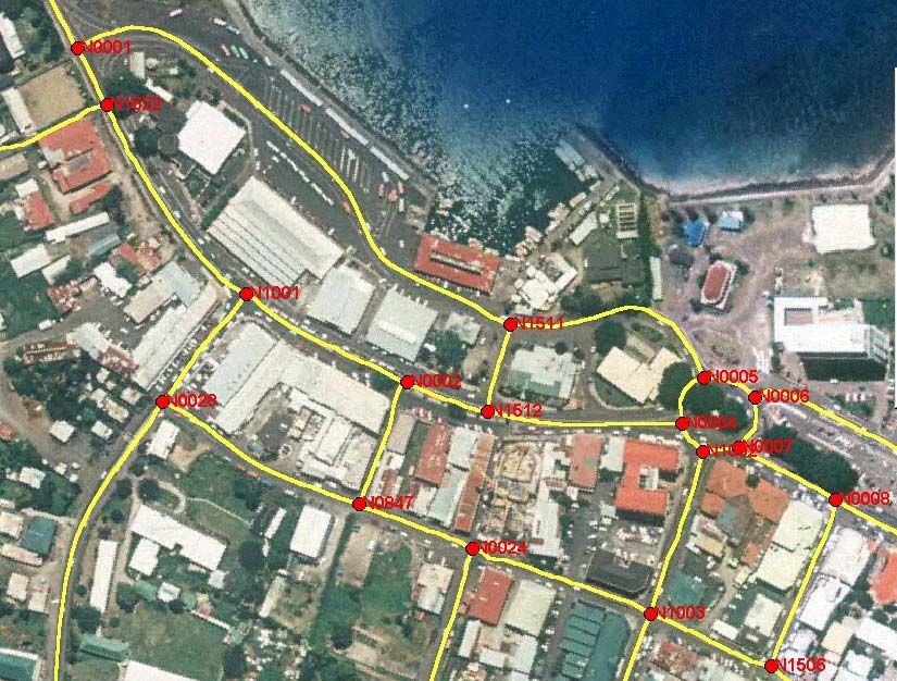
Using Google Earth on World Bank Projects

The World Bank
East Asia Transport Unit
1818 H Street NW
Washington, D.C. 20433, U.S.A.
Tel: (202) 458-1876
Fax: (202) 522-3573
Email: cbennett2@worldbank.org
Website: www.worldbank.org

A publication of the World Bank East-Asia Transport Unit
sponsored by the East Asia and Pacific Innovation Fund.

This report is a product of the staff of the World Bank assisted by
independent consultants. The findings, interpretations, and
conclusions expressed herein do not necessarily reflect the views
of the Board of Executive Directors of the World Bank or the
governments they represent.

The World Bank does not guarantee the accuracy of the data
included in this work. The boundaries, colors, denominations, and
other information shown on any map in this work do not imply any
judgment on the part of the World Bank concerning the legal
status of any territory or the endorsement or acceptance of such
boundaries.

1 February 2006                                                                      ii
Using Google Earth on World Bank Projects

                         Acknowledgements
This report was sponsored by the East Asia and Pacific Innovation Fund.

Christopher R. Bennett of the East Asia Transport Unit (EASTR) undertook the
project. He was assisted by Wenling Chen of EASTR and Kevin McPherson,
Consultant.

The project team would like to express its appreciation to the colleagues and
vendors who assisted with the project.

                     Quality Assurance Statement
Report Name:                     Prepared by:
      Using Google Earth on         C.R. Bennett
      World Bank Projects        Reviewed by:

Project Manager:                    Approved for issue by:
      C.R. Bennett                    C.R. Bennett
      cbennett2@worldbank.org
                                                                    1 February 2006

                             Revision Schedule
                                                               Reviewed    Approved
Rev. No           Date     Description           Prepared by
                                                                  by          by

1 February 2006                                                                 iii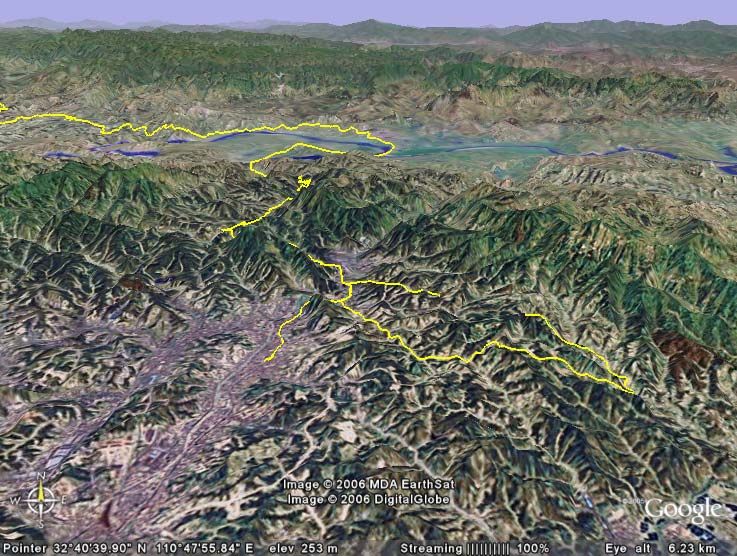
Using Google Earth on World Bank Projects

                                              Contents
1      Introduction ................................................................................. 1

2      Introduction to Spatial Data ......................................................... 3
    2.1 Introduction ............................................................................... 3
    2.2 Principles of GPS Measurement ..................................................... 5
      2.2.1 GPS Technology ................................................................... 5
      2.2.2 The WGS84 Datum ............................................................... 6
      2.2.3 The Accuracy of GPS Measurements ........................................ 6
    2.3 Satellite Images .......................................................................... 8
      2.3.1 Introduction......................................................................... 8
      2.3.2 Commercial Sources.............................................................. 8
      2.3.3 Google Earth .......................................................................10
    2.4 Automatic Analysis of Satellite Image Data ....................................10
    2.5 Issues With Spatial Data .............................................................12
3      Collecting Spatial Data ............................................................... 14
    3.1 Introduction ..............................................................................14
    3.2 Data Needs ...............................................................................14
    3.3 Handheld GPS Receivers..............................................................15
    3.4 Personal Digital Assistants (PDAs) ................................................18
      3.4.1 Introduction........................................................................18
      3.4.2 Pocket PC Creations .............................................................19
      3.4.3 GPS Data Logging Software...................................................20
      3.4.4 GPS2Google Earth ...............................................................22
      3.4.5 Conclusions on PDA Systems .................................................23
    3.5 GPS       and Digital Photographs........................................................23
      3.5.1       Introduction........................................................................23
      3.5.2       Linking Digital Photos to a GPS Receiver .................................24
      3.5.3       GPS Enabled Camera............................................................26
      3.5.4       Conclusions on GPS Referenced Digital Photographs .................28
    3.6 Comparison of Accuracy of Different Devices ..................................29
    3.7 Recommendations ......................................................................30
4      Using Google Earth to Manage Spatial Data ................................ 31
    4.1 Introduction ..............................................................................31
    4.2 Google Earth Basics ....................................................................31
    4.3 Importing Data to Google Earth....................................................35
      4.3.1 Introduction........................................................................35
      4.3.2 GE Files..............................................................................35
      4.3.3 GIS Files ............................................................................35
      4.3.4 Image Files.........................................................................36
    4.4 East Asia Pacific Google Network Drive ..........................................38
5      Conclusions and Recommendations............................................ 39

1 February 2006                                                                                     iv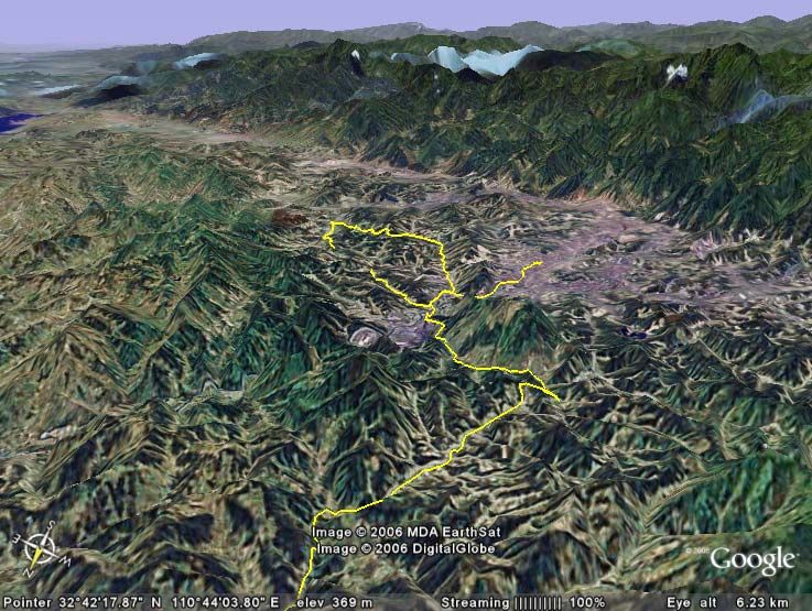
Using Google Earth on World Bank Projects

1 February 2006                                          v
Using Google Earth on World Bank Projects
1 Introduction
The World Bank undertakes a variety of projects in different locations in its
client countries. To date, the Bank has not taken full advantage of the
opportunities offered by spatial referencing of data, ie expressing locations in
terms of the latitude and longitude. While other referencing may change, for
example political boundaries, distance along the road, etc., the spatial
location stays constant.
Incorporating spatial data into Bank projects therefore offers a number of
opportunities to the Bank:
Data collected over the life of a project, from preparation through
supervision to closing, will be consistently referenced making it much
easier to confirm the benefits from the project.
Sophisticated analyses using Geographic Information Systems (GIS) can
be executed. For example:
o The number of people living within a certain distance of an all
weather road
o Access to clinics, education, markets, etc.
o Income distributions.
Many clients are in the process of collecting spatially referenced data
themselves and this could be integrated with Bank data, for example
videos of roads.
In 2005 the EAP Innovation Fund approved funding for the development of a
‘Spatial Implementation Management System’. The intent was to develop a
tool that can be used by Bank Staff in the field during preparation and
supervision for recording and monitoring issues. It would also help Bank staff
and the clients to clearly document issues; and, optionally, the general public
for viewing and reporting issues.
After the project started, Google Earth was released. This free application
provides the ideal framework for using spatial data collected on Bank projects
since it contains a three-dimensional model of the entire world, which is
continually being enhanced and updated. Its .KML files are rapidly becoming
an industry standard and are supported by a wide range of applications. The
focus of the project therefore shifted into addressing two issues: (i) how to
collect data in the field during the Bank’s project preparation and supervision
activities; and, (ii) how Google Earth can be used to manage and apply these
data.
This report presents the final results from the project. It is divided into the
following sections:
1 February 2006 1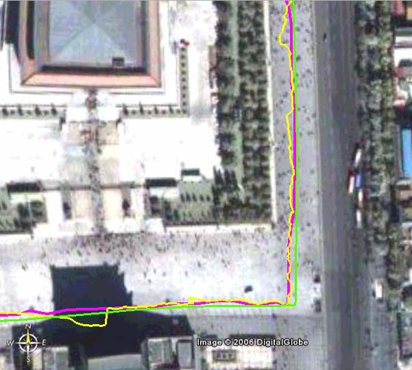
Using Google Earth on World Bank Projects Introduction to Spatial Data: An overview of spatial data and remote sensing; Collecting Spatial Data: Tools and techniques for collecting spatial data in the field; Using Google Earth to Manage Spatial Data: Using Google Earth as a data repository and manager; and, Conclusions: Conclusions and recommendations. 1 February 2006 2
Using Google Earth on World Bank Projects

2   Introduction to Spatial Data

    2.1 Introduction
    Spatial data (also called geographic data) are data that define a location. With
    spatial data one can identify where an object is located, its shape, and its
    relationship to other geographical features. The basis for referencing all
    spatial data is the latitude and longitude as this is used in the grid system
    which locates any object on the earth’s surface.

    Since the earth is roughly a sphere,
    geometry is used to identify locations.
    Lines encircling the world east-west are
    called ‘parallels’ and are used to measure
    latitude. The latitude is the angular
    distance from the equator toward either
    pole, measured in degrees. Any point on
    the equator has a latitude of zero
    degrees, written 0o. The North Pole has a
    latitude of 90o north and the South Pole
    has a latitude of 90o south. Every other                   Latitude
    point on the Earth has a latitude
    somewhere between 0o and 90o.

    ‘Meridians’ are lines that extend halfway
    around the globe from the North Pole to
    the South Pole. Meridians are counted
    from the line that passes through
    Greenwich, in London England. The
    Greenwich meridian is also known as the
    ‘prime’ meridian and has a longitude of
    0o.

    Meridians    are     used   to   measure
    longitude - that is, the angular distance
    east or west from the prime meridian.
    Like latitude, longitude is measured in
    degrees of a circle. From 0o at Greenwich
    to 180o, the meridian located halfway
    around the globe from the prime                             Longitude
    meridian. Between the prime meridian         Source: UNESCO

    and the 180o meridian are lines of west
    longitude (west of the prime meridian) and the lines of east longitude (east of
    the prime meridian).

    The latitude and longitude are expressed in two formats: degrees/minutes/
    seconds or decimal degrees. For example:

               (40d 26' 21" N, 79d 58' 36" W) or (40.446195, -79.948862)

    1 February 2006                                                                3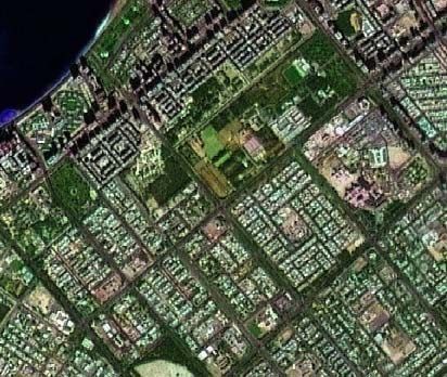
Using Google Earth on World Bank Projects
A full discussion on geographic coordinates and their conversion can be found
at: http://en.wikipedia.org/wiki/Geographic_coordinate_conversion.
Since the earth is a sphere, and maps are
‘flat’, it is necessary to project the curved
surface of the earth on the plane surface of a
map. As can be appreciated, attempting to
fit a curved surface onto a flat sheet results
in a distortion of the true layout of the
Earth's surface The most commonly known
projection is the Mercator projection which is
shown to the right. The lines of latitude and
longitude form equal sized squares, but this leads to a distortion which is
amplified as one goes further away from the equator. For example, the
Mercator projection shows Greenland larger than Africa when in fact Africa is
13 times larger than Greenland.
There are many different types of projections and they are described in detail
at: http://en.wikipedia.org/wiki/Map_projection. The key is to appreciate that
when trying to integrate the data with spatial data from other sources, spatial
data on a map may be affected by the projection used for the map.
Box 2.1: For More Information
An excellent online training course can be found at:
http://ioc.unesco.org/oceanteacher/resourcekit/Module2/GIS/Module/index.html
Additional training resources are linked to the World Bank’s GIS Thematic Group
page at:
http://gis.worldbank.org
Spatial data are stored in two formats;
Vector data: point, line and polygon data representing objects. A point is
stored as a single x,y (longitude, latitude) coordinate, a line as a pair of
x,y coordinates, and a polygon as a set of x,y coordinates, each of which
marks a vertex of the polygon; and,
Raster data: data stored in rows and columns of cells, usually images in
the form of satellite data, scanned data, and photographs.
There are a variety of techniques available for collecting spatial data:
GPS Surveys: Data are collected using a global positioning system (GPS)
receiver;
Digitizing: Existing data, such as maps, are digitized (someone traces
the lines) or scanned;
Aerial Photographs: Photo interpretation of aerial photographs, usually
stereoscopes, allow data to be captured in two and three dimensions; and,
1 February 2006 4Using Google Earth on World Bank Projects
Satellites: Satellites use different instruments to collect raster data that
can be further processed to identify objects and classes of interest, such
as land cover.
In the context of this project the focus was on using GPS systems to measure
spatial data, and to integrate the data with remote sensing data, such as
satellite images, to contextualize the data.
2.2 Principles of GPS Measurement
2.2.1 GPS Technology
The Global Positioning System (GPS) is a space-based satellite radio
navigation system developed by the U.S. Department of Defense. There are a
series of 24 satellites placed in six orbital planes about 20,200 km above the
earth’s surface. The satellites are in circular orbits with a 12-hour orbital
period and inclination angle of 55 degrees. This orientation normally provides
a GPS user with a minimum of five satellites in view from any point on Earth
at any one time—assuming one has open view of the sky. The EU is in the
process of developing Galileo which is their own version of GPS, and this
should offer improved accuracy. There is also the Russian Glonass system,
which has not been maintained so is not commonly used.
All systems work on a similar principle. Each satellite continuously broadcasts
a radio frequency signal. The GPS receiver measures the time required for the
GPS signal to travel from the satellite to the receiver antenna. The timing
code generated by each satellite is compared to an identical code generated
by the receiver. The receiver’s code is shifted until it matches the satellite’s
code. The resulting time shift is multiplied by the speed of light to arrive at
the apparent distance from the satellite (called a ‘range’ measurement).
Since the resulting range measurement contains propagation delays due to
atmospheric effects, and satellite and receiver clock errors, it is referred to as
a ‘pseudorange’. Changes in each of these pseudoranges over a short period
of time are also measured and processed by the receiver. These
measurements, referred to as ‘delta-pseudoranges’ are used to compute
velocity.
A minimum of four
pseudorange measurements
are required by the receiver
to mathematically determine
time and the three
components of position
(latitude, longitude, and
altitude). The figure to the
right shows how three
satellites are used to
establish position. This figure
does not include the fourth
timing satellite.
1 February 2006 5Using Google Earth on World Bank Projects After the four range equations are solved, the receiver has estimates of its position and time. Similar equations are then used to calculate velocity using the relative velocities instead of pseudoranges. The position, velocity and time data are generally computed once per second. 2.2.2 The WGS84 Datum GPS data are collected using what is called the WGS84 (World Geodetic System 1984) ‘datum’. Modern cartographers refer to a lumpy, flattened ball called a ‘geoid’ to measure latitude, longitude, and altitude. The ‘Earth Model’ and reference points used to prepare a map are collectively called a datum. This is basically a three-dimensional Cartesian coordinate system and an associated ellipsoid, so that WGS84 positions can be described as either x,y,z Cartesian coordinates or latitude, longitude and ellipsoid height coordinates. The origin of the WGS84 datum is the centre of mass of the Earth and it is designed for positioning anywhere on Earth. While the WGS84 datum is based on the centre of the earth, there are local datums which reflect local conditions and are therefore much more accurate. Errors of 300 m or more can arise if the wrong datum are used so if there are significant differences between GPS data and other information check the which datum was used. 2.2.3 The Accuracy of GPS Measurements GPS measurements can be very accurate but the accuracy depends on the equipment used. Until 2000 there was a random error in the GPS measurements, called ‘Selective Availability’ which meant that the 95% confidence interval for the data was +/- 100 m. However, since selective availability has been disabled, the 95% confidence intervals are now on the order of +/- 8 – 10 m. For many applications this is sufficient accuracy, although it must be recognized that 5% of the readings could be significantly worse than 10 m. The latitude and longitude measurements are the most accurate; the height the least. Survey grade GPS receivers will have sub-meter accuracy whereas consumer grade receivers are typically on the order of 5+ meters. Differential correction can be used to improve the accuracy. This uses data collected at other locations to either post-process the GPS data or transmit a real-time correction signal. Figure 2.1 illustrates the results of differentially correcting data from a low- cost Trimble Pocket Pathfinder GPS receiver. When compared to the actual position the RMS error with the uncorrected data was in the range of 1.23 – 6.32 m, which compared to a range of 1.05 – 1.58 m for the differentially corrected data. It will be noted, however, that the accuracy varied 1 February 2006 6
Using Google Earth on World Bank Projects
significantly with both methods over the course of the day as different
satellites moved in and out of view.
8
Day 1 Day 2
7
6
Uncorrected
5
RMS Error (m)
4
3
Corrected
2
1
0
08:46:37PM
08:46:56PM
08:48:22PM
08:54:27PM
08:56:02PM
08:57:37PM
08:59:12PM
09:00:47PM
09:02:22PM
09:03:57PM
09:05:32PM
09:07:07PM
09:08:42PM
09:10:17PM
09:19:20PM
09:19:39PM
09:19:58PM
09:20:17PM
09:20:36PM
09:20:55PM
09:21:32PM
09:23:07PM
09:24:42PM
09:26:17PM
09:27:52PM
09:29:27PM
09:31:02PM
09:32:37PM
09:34:12PM
09:35:47PM
09:37:22PM
09:38:57PM
06:30:56PM
06:32:27PM
06:34:02PM
06:35:37PM
06:36:57PM
06:38:37PM
Figure 2.1: Example of Variations in Accuracy Over Time
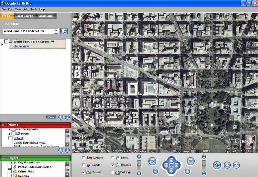
Figure 2.2 is an example of what can be achieved with a sub-meter GPS
receivers, showing the GPS data superimposed on an aerial photograph from
Apia, Samoa.
Figure 2.2: GPS Measurements and Aerial Photograph from Apia Samoa
1 February 2006 7Using Google Earth on World Bank Projects
2.3 Satellite Images
2.3.1 Introduction
Satellite images are available from a range of sources with different
resolutions. Figure 2.3 from Infoterra (www.infoterra-global.com) shows
images at different resolutions, and how data from different sources can be
combined to enhance images.
2.3.2 Commercial Sources
There are a variety of commercial sources for satellite data. Different
satellites collect different types of data, to different resolutions. Among the
sources are:
Satellite Resolution (m) Satellite Resolution (m)
ASTER 15 - 90 Landsat 15 - 30
ENVISAT 10 – 30 Quickbird 0.61 – 2.88
EROS 1.8 Radarsat 8 – 100
ERS 25 SPOT 5 - 20
IKONOS 1-4 TerraSAR-X 1
IRIS 15 - 90
The cost of images is proportional to the resolution and so there is often a
compromise between what is desired and what can be afforded.
Satellites collect data in different bands. These are:
Visible Blue: Designed for water penetration, making it useful for coastal
water and lake bathymetry and sediment load mapping. Also useful for
differentiation of soil from vegetation, and deciduous from coniferous
flora; it is lower for vegetation and coniferous forest.
Visible Green: Measures visible green reflectance peak of vegetation for
vigor assessment.
Visible Red: Discriminates between different types of vegetation.
Near Infrared: Identifies healthy vegetation and delineates water bodies.
Short wave Infrared: Indicative of vegetation moisture content and soil
moisture. Can also identify rocks and hydrothermal altered zones for
mineral exploration.
Thermal Infrared: For thermal mapping activities such as heat intensity,
vegetation and crop analysis, thermal pollution.
Figure 2.4 shows the different bands collected by different satellites.
By combining information from different satellites and different bands on
obtains an enhanced overall image. This can be observed from the images in
Figure 2.3 where some examples show combination effects.
The easiest way to obtain satellite data is from a commercial consolidator.
They will consider the data requirements, available budget and assemble an
appropriate package. It should be noted that it can take several months to
acquire the images, depending upon what is required.
1 February 2006 8Using Google Earth on World Bank Projects
Landsat ETM+, 30 meter resolution, false color infra- Landsat 7 ETM+, 15 meter resolution, natural color.
red. merged with the 30 meter color bands.
Landsat 7 ETM+ data merged with 10 meter SPOT Pan Landsat 7 ETM+ data merged with 6 meter IRS Pan
black and white data to produce a 10 meter color black and white data to produce a 6 meter color
dataset. dataset.
Ikonos 4 meter natural color image. Can be merged QuickBird 62 centimeter data over the port of Abu
with 1 meter Ikonos Pan data to provide a very high Dhabi. This is a merge of the black and white 62cm
resolution color dataset. data with the lower spatial resolution color data.
Source: www.infoterra-global.com
Figure 2.3: Examples of Different Satellite Resolutions
1 February 2006 9Using Google Earth on World Bank Projects
Source: www.infoterra-global.com
Figure 2.4: Satellite Bands
2.3.3 Google Earth
Google Earth (GE) is described at: http://en.wikipedia.org/wiki/Google_Earth.
GE is an application which is free to use and is supported by satellite images
and a three-dimensional terrain model for the entire world. With accuracies
typically of 15 m or better, it is an ideal platform for using spatial data. The
features of GE are:
The data are stored in WGS84 datum which means that it is not necessary
to process GPS data prior to loading to GE;
Resolution generally on the order of 15 m;
Most data are less than 3 years old. They are sourced from different
providers; and,
High resolutions (1 m or better) available in some areas, such as US
cities. More high resolution data is being provided over time.
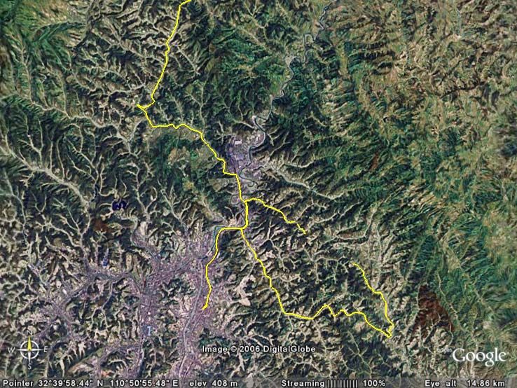
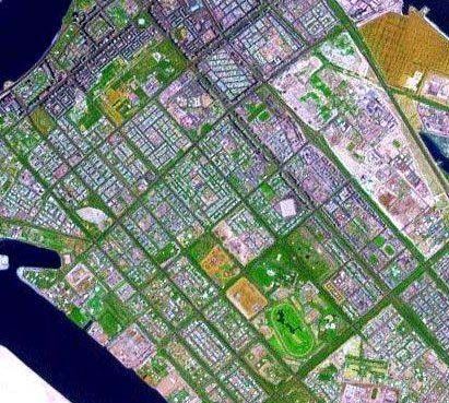
As an illustration of the different resolutions available in GE, Figure 2.5
contrasts the cities of Wuhan and Beijing. In Wuhan, it is not possible to
identify minor roads with any accuracy; in Beijing individual vehicles are
visible. Thus, depending upon the requirements additional data may be
required beyond that available in GE.
GE is discussed in detail in Section 4.
2.4 Automatic Analysis of Satellite Image Data
There are a variety of automatic analyses that can be done with satellite
image data. The industry is rapidly developing as new technologies become
available and the cost of satellite images decreases.
As mentioned earlier, satellites collect data with different bands. Figure 2.6
shows an example how spectral classification can be used to identify features
from an image1.
1
Presented by Vijay Modi from Columbia University to the World Bank, January, 2006.
1 February 2006 10Using Google Earth on World Bank Projects
Wuhan – 12,052 ft Beijing – 1,397 ft
Figure 2.5: Comparison of Google Earth Image Resolutions from China
Fields Woods Water Houses
Source: Modi (2006)
Figure 2.6: Example of Spectral Classification
Of interest to many is the location, and extent, of the road network. Under
certain circumstances this data can be automatically extracted from images.
The left image in Figure 2.7 shows data from an IKONOS satellite that was
automatically analyzed to identify road sections based on the pixels2. Using
this approach, it proved possible to reliably extract road centerlines for an
urban area (see the right image).
2
Finding Road Networks in IKONOS Satellite Imagery. Available for download from
http://www.spaceimaging.com/whitepapers_pdfs/2003/Finding%20Road%20Networks%20in%20
IKONOS%20Satellite%20Imagery-ASPRS%202003.pdf
1 February 2006 11Using Google Earth on World Bank Projects
Source: Space Imaging
Figure 2.7: Examples if IKONOS Road Centerline Extraction
Depending upon the type of data of interest, it may be practical to extract it
automatically from satellite images. With regard to roads, it is most reliable in
urban areas where accuracies of over 85% have been reported. For rural
roads, especially unpaved ones, it is much more difficult.
2.5 Issues With Spatial Data
Data are expensive to collect and to maintain once collected. While data costs
peak during the data
collection period, the data
need to be maintained which
requires an ongoing
commitment and investment
(see the figure to the right
from UNESCO). For example,
about 5% of a country’s road
network changes each year
and unless the data are
maintained the network
representation will soon become outdated.
There are many sources of GIS data and the tendency is to assume that data
provided are ‘correct’. However, it has been found more often than not that
data have some problems. When using data from other sources it is therefore
important to ask a series of questions such as:
How recently were the data collected?
Who collected it?
How accurate are positional and attribute features?
Does the data seem logical and consistent?
Is the data relevant to the project at hand?
If the data were digitized from some source:
1 February 2006 12Using Google Earth on World Bank Projects
oIn what medium was it originally produced?
oWhat is the areal distribution of the data?
o To what map scale was the data digitized?
o What projection, coordinate system, and datum were used in
maps?
How was the data checked?
Why was the data compiled?
What is the reliability of the provider?
As data becomes more widely shared the concept of metadata is becoming
more important. Metadata describes the history and accuracy of the data set,
and there are a variety of metadata standards available. It is important that
each dataset has metadata provided for it.
1 February 2006 13Using Google Earth on World Bank Projects
3 Collecting Spatial Data
3.1 Introduction
This section describes the results of tests to collect spatial data in the field.
The focus was on how to collect data for project preparation and supervision
in a low-cost, simple but effective way. Three approaches were considered:
Hand-held GPS receivers;
Personal Digital Assistants; and,
Digital photography with GPS.
Each of these are discussed individually after the general data needs are
described.
3.2 Data Needs
There are two types of spatial data that are commonly collected:
Point data: This is data pertaining to a single point, such as a building;
and,
Continuous data: This is data which is a set of continuous points, such
as a road.
In the context of project preparation and supervision, most data will be point
data. This is because we are interested in the location of single items (eg
environmental and social issues). This point data would be collected over the
course of the project. Continuous data, on the other hand, is often only
collected once, such as when the location of a project road is defined.
An important element of quality control of data collection is to ensure that
standard terms are employed. For example, a location with excessive noise
could be described as ‘high noise’, ‘bad noise’, or ‘noisy’ by different people.
By using drop-down menus when collecting data instead of free-form entry,
consistency is guaranteed.
Based on interviews with Bank staff, the list of issues in Table 3.1 was
established. When an issue needs to be spatial referenced, the ‘Area’
abbreviation in parentheses () is used with the actual issue, for example:
SE – Air Pollution
SR – Property Replacement
E – Design Issue
In addition to the issues, two other sets of data were identified as required:
1 February 2006 14Using Google Earth on World Bank Projects
Project ID; and,
Name of person collecting the data.
Table 3.1: Issues to be Spatially Referenced
Area Issue
Air Pollution
Dust Pollution
Noise Pollution
Safeguards – Environment (SE)
Property/Land Damage
Water Pollution
Other
Compensation Level
Completion of House Demolition
Safeguards – Resettlement (SR) Completion of Land Acquisition
Property Replacement
Other
Construction Quality
Design Issue
Engineering (E)
Safety Issue
Other
Clinic/Hospital
Casting Yard
Construction Camp
Inventory (I)
Materials Storage
School
Other
Other Other
3.3 Handheld GPS Receivers
There are a variety of different types of GPS receivers on the market, ranging
from small handheld consumer units to larger systems which are carried in
backpacks. The accuracy of the receivers varies significantly with cost. Using
a handheld consumer grade GPS costing on the order of US$
200 the accuracy is at best 5-10 m; with a US$ 10,000 system
such as Starfire the accuracy is at the cm level. The two main
companies supplying consumer grade models, which have
more than sufficient accuracy for the Bank’s needs, are Gamin
and Magellan. Google Earth Pro will import data directly from
both these units.
The testing was done using a Garmin e-Trex Legend which cost
US$ 170. This unit was selected because (i) Garmin is more
widely supported by data processing applications than
Magellan; (ii) it had the capacity to store a moderate amount
of route data; and, (iii) as 12 parallel channel GPS receiver
continuously tracks and uses up to 12 satellites to compute
1 February 2006 15Using Google Earth on World Bank Projects
and update the position which should give good results.
The Legend was used both in handheld mode and with a special automotive
bracket. The latter consists of a suction cup with mounting system for affixing
the GPS receiver to the vehicle’s window. This was a very effective way of
collecting the data when in the field, especially on rough and curvy roads.
The system can store point or continuous data. Point data,
called ‘Waypoints’, are stored by pressing the unit’s thumb
stick and defining a description of the point. With the e-
Trex Legend up to 1,000 waypoints can be stored. The
entering of the point data description is somewhat tedious
since there is no keyboard to enter the data; each letter
must be highlighted and selected.
For continuous data the user must define
how the data is sampled. The sampling is
set under Main Menu|Tracks|Log
Setup. The default settings are shown to
the right. The data can be on a time basis
(every n seconds) or a distance basis
(every n meters/miles). For the purpose of testing a distance
basis was generally used. With its 8 MB of memory, the
Legend can store about 10,000 observations before the data need to be
downloaded. This can be used as a guide to the sampling interval when taking
continuous measurements.
Box 3.1: Downloading and Converting Data
There are a large number of different GPS receivers on the market with
different data formats. The most comprehensive effort for downloading and
converting GPS data between different applications is ‘GPSBabel’ found at:
http://www.gpsbabel.org/
If you want to download and process GPS receiver data this is the best place
to start looking for solutions.
The Legend has a RS-232 serial cable for
downloading the data to the computer. This is
potentially a problem as many newer computers do
not have an RS-232 port. Google Earth Pro has the
facility to import Garmin data, however, it was
found that the program GPS Utility
(www.gpsu.co.uk), a US$ 55 application was more
flexible as it allowed for the data to be manipulated
and combined into a individual files.
To interface GPS Utility with the Legend the
interface needs to be set up. This is done by
1 February 2006 16Using Google Earth on World Bank Projects
selecting GPS|Setup and selecting the ‘Garmin’ as the receiver. Once this is
done you select GPS|Connect to connect to the receiver. If successful, the
software displays the message ‘Connected to e-Trex Legend Software Version
3.70’ at the bottom of the screen.
Selecting GPS|Download All opens the screen
to the left. This allows you to select what data
to download. Normally one downloads
everything.
Once the data are loaded into GPS Utility they
should be checked and any readings not
required should be deleted. This is done by
using the Filter option, or manually selecting
records.
The data are then converted to
another format by selecting
File|Save As. The three most
useful formats are:
GPX Interchange File: This is
a standard file for exchanging
GPS data and can be read by
many applications;
Shape Trackpoint File:
Suitable for being read by
ArcGIS; and,
Google Earth KML File: A .KML
file which can be read directly
by Google Earth.
An alternative approach is to use the free web based program ‘GPS Visualizer’
(http://www.gpsvisualizer.com/map?form=googleearth). This takes a GPS file
and creates a GE .KML file.
Box 3.2: Using the Handheld GPS System in the Field
It was found that the most convenient way of using the units was to leave
them turned off until the site was reached. By going to the start of the site,
turning the unit on, and then traveling to the end of the site before turning
the unit off, a single line was established. During the data processing stage
this could be easily identified and saved into a unique file for that section.
The following are the conclusions with respect to using handheld GPS units:
1 February 2006 17Using Google Earth on World Bank Projects The units are very simple to use, especially for continuous data collection. With their low cost, they are ideal for using for field data collection. The optional protective case should be used with the unit to prevent damage; the car mount is essential when doing field surveys measuring road alignments. The batteries last up to about 17 h and, even if replaced, any data in the unit are retained. For extended surveys the optional cable which powers the unit from the cigarette lighter should be used. The RS-232 download cable could be a problem since not all computers have an RS-232 port. Other more expensive models have a SD Card for storing data which would be a better approach to use. The accuracy of the Legend is equivalent to a PDA with a GPS receiver. The time to start the unit and get satellite fixes can be long, well in excess of the ‘cold start’ time given in the Legend specifications. 3.4 Personal Digital Assistants (PDAs) 3.4.1 Introduction PDAs are handheld computers. There are essentially two standards of PDA: Windows Pocket PC Based; or, Palm OS Based. From a functional point of view, there are relatively few differences between the two standards. When it comes to GPS data recording, the Dell Pocket PC systems were considered to be more appropriate since they contained a CF Card slot, which various GPS receivers could be connected to, as well as easy expansion through an SD Card. A Dell Axim X5 was therefore used in the project with a Haicom HI-303S CF Card GPS Receiver. The cost of the PDA with GPS was < US$ 500. Three approaches were tested for collecting the data: A custom application written using ‘Pocket PC Creations’. This software allows for the rapid development of data entry forms which will store the spatial data against the user entered data; An off-the-shelf applications called ‘GPS Dash’ and ‘Tom Tom Navigator’ which could store data continuously; and, An off-the-shelf application called GPS2GoolgeEarth which is designed to record data for Google Earth. 1 February 2006 18
Using Google Earth on World Bank Projects 3.4.2 Pocket PC Creations The Pocket PC Creations (PPCC) application was developed using the PPCC environment. This is a very simple to use framework where users can custom create data entry pages, each with customized fields. The PPCC Data Entry s split into “Pages”. Every new session has a number of pages, which can be navigated to by tapping the “Next” or “Previous” buttons at the bottom of the screen. The system was designed with three types of data entry: Drop-Down Lists which permit selection of choices set up in pre- defined lists as seen below. GPS Coordinates which are automatically updated from the GPS (if attached). Tapping on the field should store the current GPS location in SIMS. Free-Format Data Entry boxes permit entry of free-format data from the software keyboard on the Pocket PC. When data are entered the GPS co-ordinates for the record are stored. After the survey, the data are synchronized to a notebook computer and viewed in Microsoft Access. 1 February 2006 19
Using Google Earth on World Bank Projects
From Access the data can be exported as a comma
delimited file and then imported to a GIS.
The software was found to work fine and it was
extremely flexible for customizing to the exact data
collection format. The main disadvantages to using it
were:
it could only record point data so if continuous data were required a
second system would need to be used; and
the cost for a large number of licenses would be excessive when
compared to other options, even as far as writing a custom application.
The software is ideally suited for proof-of-concept or situations where there
are numerous different types of data collection forms to be used since these
can be quickly and easily developed.
3.4.3 GPS Data Logging Software
There are a number of GPS data logging programs on the market. These
simply record the data transmitted by the GPS receiver into a log file as it is
received, usually at 1 s intervals. The files are in NMEA 0183 format which
can be processed for importing into a GIS or Google Earth.
Two applications were tested. GPS Dash is a low cost (< US$ 30) application.
GPS Log is a program supplied with TomTom Navigator. Both had similar
results, the only difference being the interface. Figure 3.1 shows the screens
from GPS Dash.
Figure 3.2 shows typical output from a GPS data logging program, here
TomTom navigator. After four lines of headers the GPS data there is a series
of NMEA strings.
It is necessary to convert the data from any data logging program into a
suitable format for reading by a GPS or Google Earth. The program GPS Utility
(www.gpsu.co.uk) that was used for downloading the Handheld GPS data was
found to be ideal for this task. It is able to read a range of different input file
formats and convert the data to a variety of different outputs. An additional
1 February 2006 20Using Google Earth on World Bank Projects
benefit was its ability to combine several data logging files into a single file.
Figure 3.3 is an example of the .PGL data from Figure 3.2 in GPS Utility.
Figure 3.1: Example of GPS Dash Software
Figure 3.2: Example of GPS Data Logging Output
Figure 3.3: Processing of GPS Data Logging
1 February 2006 21Using Google Earth on World Bank Projects
The two PDA data collection programs were found to work very well. The only
major problem was their inability to store point data.
3.4.4 GPS2Google Earth
GPS2Google Earth (www.s-gps.com) is a simple PDA application costing only
US$ 19 designed to create Google Earth .KML files. It logs data from the GPS
receiver continuously, at user defined sampling intervals (see Figure 3.4), and
can also create point data which are called ‘Placemarks’. The user can enter a
description of the placemark data using the PDA stylus and virtual keyboard.
Once data are collected, all data are exported to a .KML file using the export
function. There are no options to save the data into other file types.
Continuous Data Point Data Export to KML
Figure 3.4: GPS2Google Earth Screens
The software was very simple to use and worked well. Both its cost and
simplicity are attractive. Some enhancements to the software would make it
even better, including:
The GPS setup must be done every time the software is started. This
quickly becomes tedious and is a potential source of problems since new
users may not enter the correct data.
There is no capacity to have drop-down menus for quickly entering
descriptions of placemarks and to ensure data consistency.
It is difficult to manage data when it is stored in a single file. Separate
files should be created with a unique date and time stamp representing
each time a new session is started.
The above suggestions should not detract from the software. It is a very
useful PDA data collection application.
1 February 2006 22Using Google Earth on World Bank Projects
3.4.5 Conclusions on PDA Systems
PDAs are a good way of collecting field data. On the basis of the testing of the
different options the following are the conclusions:
PPCC: This application allowed for the rapid development and testing of
the concept of GPS data collection. In that regard it was ideal for the
project. However, it is not appropriate as a long-term solution for the
following reasons:
o The system is moderately difficult to install and maintain on
PDAs and requires a fairly good level of computer skills to get
working correctly.
o It does not allow for the collection of point and continuous data
at the same time.
o The licensing costs of about US$80 per license can become
costly if looking at widespread use.
o It requires Microsoft Access as the back-end database which is
an additional cost.
GPS Dash/GPS Log: These applications are low cost, very simple to use
and have a good user interface. They record at 1 s intervals the GPS co-
ordinates, displaying the number of satellites and other data. They
produce an NMEA 0183 output file (usually a .PGL) which is industry
standard and can be read by other programs. They are well suited to
collecting continuous data, but not for point data.
GPS2Google Earth: This application is low cost, very simple to use and
meets the requirements for data collection. It records both point and
continuous data so produces both types of files required for data
collection. With slight modifications it would be ideal for PDA spatial data
collection.
Box 3.3: Using the PDA GPS System in the Field
Due to their relatively short battery life, at least compared to the 17h for a
hand-held GPS unit, it is advisable to operate the PDA with an automotive
power cable. This ensures that it is continuously recharged. The units should
also have a protective case, such as a Rhinoskin, as they are subjected to
extreme conditions.
3.5 GPS and Digital Photographs
3.5.1 Introduction
Digital photos, in the form of JPEG (.jpg) files, can be provided with spatial
data (latitude, longitude and elevation) in the photograph headers. When
imported to a GIS or Google Earth, a marker is placed at the location where
1 February 2006 23Using Google Earth on World Bank Projects
the photograph is taken. There are two ways that spatial co-ordinates can be
associated with images:
Linking the image taken with any digital camera to GPS data based on the
time when the photo was taken; or,
Using a camera with an integrated GPS receiver.
Each of these approaches were tested in the project and the results are
described in the following sections.
3.5.2 Linking Digital Photos to a GPS Coordinates
While it is possible to manually insert the latitude and longitude into a .JPG
file header, this is not a straight forward process. It would also be
cumbersome since one would need to first manually record the spatial
location and then insert these data to the header.
It is much easier to use dedicated software to do this, and there are several
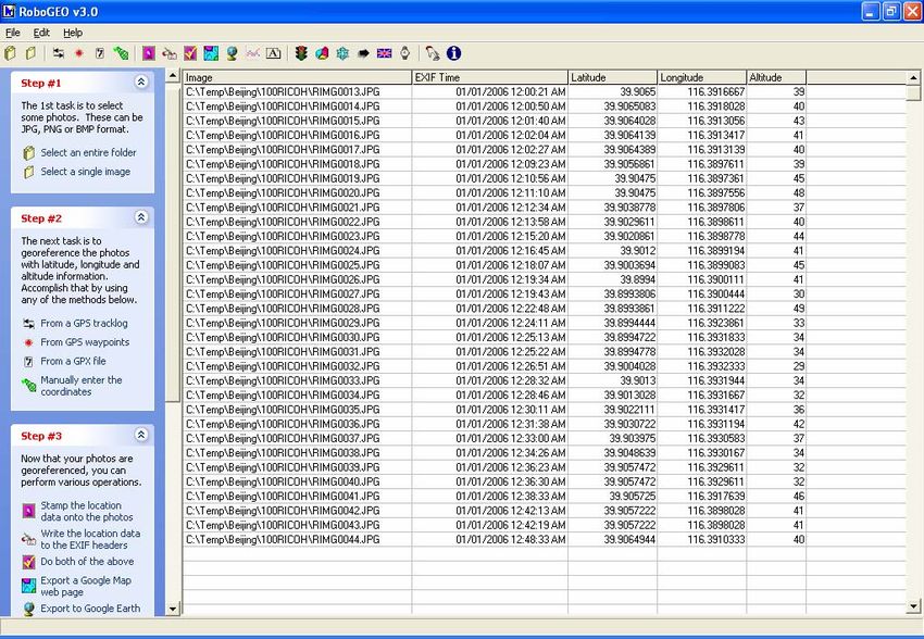
applications available. For this project the software RoboGeo v 3.0
(www.robogeo.com) was used. This application costs US$ 23 for personal
use; US$ 50 for a single commercial license.
The software is very straight forward to use. One selects the folder with the
digital photos and then the file which contains the GPS data. The software
then assigns the GPS co-ordinates to the photos by matching the time
stamps. Figure 3.5 is an example of the RoboGeo output after geo-
referencing some images.
Once the images have been geo-referenced you can
perform several options. The most useful are to (i)
write the location data to the .JPG headers and (ii) to
export the data to Google Earth.
With the latter the software creates a Google Earth
.KMZ file which is a compressed file containing all the
photos. For displaying in Google Earth it was found that
a maximum size of 450 pixels gave a good compromise
between the size of the image and the available space
for displaying. This value is entered during exporting as shown in Figure 3.6.
1 February 2006 24Using Google Earth on World Bank Projects
Figure 3.5: Example of RoboGeo after Geo-referencing
Figure 3.6: Exporting Images to Google Earth
In using the software the following was found:
It is useful if you have a photo taken at a known location, for example an
intersection, which can then be used to test the accuracy of the
assignment.
1 February 2006 25Using Google Earth on World Bank Projects
The key to success is, of course, getting the correct time synchronization
between the GPS receiver and the camera. If the camera’s time is not set
to the same time as the GPS receiver then it is necessary to enter a time
offset under ‘Specify the camera offset button’ . If the time offset is
wrong, then many photos will have the same GPS co-ordinates. Having a
photo taken at a known location is an easy way to confirm the
synchronization.
3.5.3 GPS Enabled Camera
A GPS enabled camera is the most simple way to link digital photographs to
spatial co-ordinates. When the photo is taken the spatial co-ordinates are
automatically entered into the .JPG header.
The only camera currently available which is
GPS enabled is the Ricoh G3-Pro. This camera
has a CF card slot so the GPS receiver is
attached to the camera in the same way as
with the PDA. It is a 3.3 mega-pixel camera
which records data on an SD card.
The camera comes with a ruggedized rubber
cover which protects it against dropping. It is
a very well designed and robust design.
The G3-Pro has an additional feature: it is possible
to enter data to be associated with the image.
These data are also stored in the header file and
can be viewed with the image. Ricoh also provides
software to convert the photos and headers into
Word, Excel and GE documents.
The user can create up to five different
‘Memo’ fields to be used with the
images. The buttons on the rear of the
camera are used to step through the
fields and select the appropriate values.
The screen to the right shows the
software used to create the file. For this
project three memo fields were used:
Project ID;
Issue (see Table 3.1); and,
User Name.
The software creates a formatted text
file which resides on the camera’s
memory card.
1 February 2006 26Using Google Earth on World Bank Projects
For the purpose of testing, the camera was used with a GlobalSate SiRF Star
III CF-Card GPS receiver. It was found that this was an excellent unit, with
much faster acquisition times than the Haicom CF-Card GPS receiver used
with the PDA GPS testing.
When the camera is first turned on it attempts to locate the GPS satellites.
The LCD screen on the camera has a display as shown in the left of Figure
3.7. Once there is a GPS fix, the latitude and longitude are shown as in the
right of Figure 3.7. When the camera was used in the same general area the
time from turning the camera on until a satellite fix was on the order of 10 s,
depending on how clear the view was of the sky. In new areas it could take
up to one minute or longer. It is therefore advantageous to turn the camera
on as soon as possible before taking a photo.
No Satellite Fix Satellite Fix
Figure 3.7: Ricoh G3-Pro Screens
The memo field function is very straight forward to use. It is possible to use
the same memo field continuously without having to re-enter the data. In
field testing it was found that the proposed issues list presented in Table 3.1
worked well and did not need to be supplemented.
The only shortcoming noted with the camera was its inability to record
continuous data. It would be very useful if the camera could create a
continuous GPS log while it was turned on.
As mentioned earlier, Ricoh provides software which processes the data. It
will automatically read the images and create Word, Excel and Google Earth
.KMZ files. Unfortunately, there was a problem with the software during the
evaluation so it was not possible to test it.
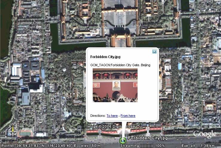
In lieu of the Ricoh software, the program RoboGeo (see Section 3.5.2) was
used to read the photos and create a Google Earth .KMZ file (or other GIS
format). Figure 3.8 is an example of this for a photograph taken at the
entrance to the Forbidden City in Beijing in Google Earth. The image is
correctly referenced.
1 February 2006 27Using Google Earth on World Bank Projects
Figure 3.8: Example of GPS Camera Photo in Google Earth
Box 3.4: Using the Ricoh Pro-G3 Camera in the Field
The camera is very well designed and simple to use. The only problem found
was that the battery was consumed very quickly. It is therefore advisable to
recharge it after each day. Fortunately, the camera is designed to also
operate off AA batteries, so these should be carried as a spare. The SD card
should have a minimum of 256 MB of storage to save the need to regularly
download the data to the computer.
3.5.4 Conclusions on GPS Referenced Digital Photographs
Digital photographs are regularly taken during supervision missions. By
recording the GPS co-ordinates where the photos are taken they will be linked
to the precise location and can be displayed in a GIS or Google Earth. Over
time layers of data can be assembled and reviewed to obtain a time history of
the project.
The Ricoh GPS camera is the perfect tool for supervision and project
preparation. By automatically geo-referencing the images, all the user needs
to do is to download the photos to Google Earth or a GIS.
The alternative is to use a handheld GPS receiver and a regular digital
camera, using RoboGeo or similar to geo-reference the images. However, this
requires moderate technical skills so is less desirable than the GPS camera.
1 February 2006 28Using Google Earth on World Bank Projects
3.6 Comparison of Accuracy of Different Devices
In order to assess the relative performance of the three different techniques,
ie handheld GPS, PDA with GPS and the GPS Camera, a test was done
wherein the same route was walked with all three units collecting data ate the
same time.
The tests were done in Tiananmen square in Beijing. Starting at the NW
corner of the square, a complete circuit was made. Every 100 m, as given by
the handheld GPS unit, a digital photograph was taken which gave the co-
ordinates of the photograph location. The data were processed using GPS
Utility and RoboGeo v 3.0 as described earlier, and imported into Google
Earth.
Figure 3.9 shows the results of the testing. The following was found:
There was good agreement between all three systems. The PDA GPS
receiver was found to loose satellite lock easier than the other two
systems. An example of this problem is at the south end of the photo
where there was a loss of satellite in the shadow of the building.
The distance measurements in Google Earth corresponded to the 100 m
measurements of the handheld GPS.
It will be noted that the measurements are offset by approximately 14 m
from the edge of the sidewalk where they were taken. This was found on
both sides of the square and is an indication of the differences between
the WGS84 datum measurements and the Google Earth co-ordinates.
Figure 3.9: Comparison of GPS Devices at Tiananmen Square
1 February 2006 29Using Google Earth on World Bank Projects 3.7 Recommendations On the basis of the testing of data collection equipment the following are the recommendations: The Ricoh G3-Pro camera (about US$ 1000 with all accessories) with embedded GPS is the most simple way to collect spatial data on projects. The memo fields are easy to use and allow each image to be tagged with key information pertaining to the project and the subject of the photo. The list of issues in Table 3.1 proved sufficient in the testing, but could be easily augmented. A maximum of 50 memo items can be used, this is too few for a region with many different projects where the camera would be shared. The only disadvantage of the camera was its inability to record continuous data. An alternative to the Ricoh camera is a GPS equipped PDA (about US$ 500 with all accessories) running a simple application such as GPS2Google Earth. Compared to the Ricoh camera, this would require a higher level of technical expertise to operate correctly and transfer data to the computer. Handheld GPS units are the least expensive (below US$ 200) way of collecting GPS data. Simple to operate, they can record point and continuous data. The transferring and processing of the data requires a moderate level of technical expertise. It is possible to use a handheld GPS with any digital camera to embed the GPS co-ordinates on the image using software such as RoboGeo. 1 February 2006 30
Using Google Earth on World Bank Projects
4 Using Google Earth to Manage Spatial Data
4.1 Introduction
The project adopted Google Earth (GE) (http://earth.google.com) as the
framework for managing spatial data. This application has a three
dimensional terrain model of the entire world in its database, as well as other
attributes such as cities and roads, to different resolution.
There are two versions of GE available:
Google Earth basic is free to use on any computer; and,
Google Earth Pro has a license fee of US$ 400 and has enhanced features
which allows for data to be manipulated.
The project procured Google Earth Pro with extensions to read GIS files.
This section describes the use of GE on the project and general observations
on the software.
Box 4.1: Google Earth vs. Geographic Information Systems (GIS)
Google Earth is not a GIS, rather, it is more of a data visualization tool. A full
GIS, such as ArcGIS which the Bank has licenses for, contains a number of
tools for manipulating and reporting on spatial data. These tools are not
available in Google Earth—the only tool is to measure distances. However, no
GIS has available the background images that Google Earth does so for
visualizing data there is no better system available, and it is free to use.
In the event that analyses and reporting of spatial data is required, the data
should be imported to a GIS and analyzed there. The .KML file format used by
Google Earth is rapidly becoming a data standard and it can be converted to
GIS formats using a variety of applications, such as GPS Utility (see Section
3.3).
4.2 Google Earth Basics
When started, GE shows the image of the world. Entering an address into the
search box at the top left will zoom the image to that address. Figure 4.1
shows the display when zooming in to the World Bank’s office in Washington
D.C.
The GE controls are at the bottom of the screen, and are as shown in Figure
4.2. The image can also be moved by holding down the mouse button and
‘dragging’ the image in the appropriate direction.
1 February 2006 31Using Google Earth on World Bank Projects
Figure 4.1: Google Earth Opening Screen
Zoom In/Out Tilt
Rotate Left Rotate Right
Orient North Reset Tilt
Move Image
Figure 4.2: Google Earth Controls
The ‘Tilt’ function is a particularly useful feature of GE. GE contains a three-
dimensional terrain model for the entire world. Using the Tilt function, one
can orient the image so that the surrounding terrain is visible. This helps to
contextualize the data based on the local environment.
By default, GE sets the ‘Elevation
Exaggeration’, ie the vertical elevation scale,
to 1, which is 1/3 of the true elevation. To
properly visualize the terrain this value
should be set to 3 under the Tools|Options
screen, as shown to the right.
1 February 2006 32Using Google Earth on World Bank Projects
Figure 4.3 and Figure 4.4 show the same image without and with tilt. When
tilted, the mountainous terrain that the highway passes through can be
observed (this is the Shiman highway project in Hubei, China). In Figure 4.5,
the tilted image is rotated to looking in a southern direction.
Figure 4.3: Image With No Tilt
Figure 4.4: Image With Tilt
1 February 2006 33You can also read