GIB Fire Rated Systems - Specification and Installation Manual CBI 5113 OCT 2012
←
→
Page content transcription
If your browser does not render page correctly, please read the page content below

CBI 5113

                                              OCT 2012

     GIB Fire Rated Systems
                          ®

      Specification and Installation Manual

Appraisal No.289 [2012]
What is New?
                                                    Most specifications in this technical literature are similar to
                                                    those published in ‘GIB® Fire Rated Systems January, 2006’
                                                    with the following additions;
                                                    • Compliance has been aligned with the 2012 provisions of the
                                                      New Zealand Building Code for the Protection from Fire
                                                    • Surface Finish Properties have been tested in accordance
                                                      with the ISO 5660
                                                    • Steel joist floor/ceiling specifications have been added
                                                    • Stability of fire rated elements has been clarified and a
                                                      simple boundary wall detail is included
                                                    • Penetration details, previously
                                                      published in separate literature, have
                                                      been included. Reference is also made
                                                      to a listing of proprietary penetration
                                                      seals now available on www.gib.co.nz or
                                                      scan the QR code

                                                    Use Only the Current Specification
                                                    This publication may be superseded by a new publication.
                                                    Winstone Wallboards Ltd accepts no liability for reliance upon
                                                    publications that have been superseded. Before using this
                                                    publication check whether this is the current publication; simply
                                                    call the GIB® Helpline on 0800 100 442 or visit www.gib.co.nz.
GIB® FIRE RATED SYSTEMS

                                                       this book superSedes the
                                                       following publications
                                                       • GIB® Fire Rated Systems - January 2006
                                                       • Penetrations in GIB® Fire Rated Systems - August 2003
                                                       • GIB® Garage Boundary Wall Technical Bulletin - March 2009
                          Appraisal No.289 [2012]

     2
GIB Fire
                    ®

Rated Systems
Specification and Installation Manual

New Zealand Building Code                                           Giving you peace of mind
Compliance                                                          • The New GIB® Fire Rated Systems 2012 have been
The New Zealand building code requirements for fire safety            BRANZ Appraised, providing assurance that the
represent the minimum allowable standard of protection to             systems in this technical manual have been sourced
ensure the health and life safety of building occupants.              from organisations with accredited quality assurance
The building code provisions do not aim to protect the                and most importantly, comply with the New Zealand
building itself, nor its contents, and often fall short of what       Building Code (NZBC)
people and businesses expect and find acceptable.
                                                                    • Compliant with the 2012 provisions of the NZBC for
An effective fire design not only addresses life safety, but          Protection from Fire, including new Surface Finish
also considers personal property protection and ongoing               Properties
business viability after exposure to a possible fire.
                                                                    • Additional performance aspects can be added to
Beware of Substitution                                                the New GIB® Fire Rated Systems 2012 through the
                                                                      substitutions in the table below
The performance of fire rated systems is very sensitive to
design detailing and construction practices. All GIB® Fire Rated
Systems have been developed specifically for New Zealand
conditions and independently tested or assessed to ensure the
                                                                      Customised Design Solutions
required level of performance. Therefore, it is important to use      The systems detailed in this book should cover most
only GIB® branded components where specified and closely              common situations where fire resistance is required.
follow the specified design details and construction practices,       However, for special projects where specific
so you can be confident that the required level of fire safety is     performance is necessary, GIB® Technical Services can
achieved on site.                                                     assist you to develop a customised solution. Simply
If you require any further information please don’t hesitate to       contact us through the GIB® Helpline on 0800 100 442.
call our GIB® Helpline on 0800 100 442.

Winstone Wallboards Ltd accepts no liability if GIB® Fire Rated Systems are not used in accordance with
instructions contained in this publication.
                                                                                                                              GIB® FIRE RATED SYSTEMS

                              ACCEPTABLE ALTERNATE  GIB® PLASTERBOARDS
 SPECIFIED GIB®                                    GIB BRACELINE®
                              GIB® STANDARD                           GIB AQUALINE®      GIB TOUGHLINE®     GIB ULTRALINE®
 PLASTERBOARD                                      GIB NOISELINE®
 10mm GIB FYRELINE®           13mm                 10mm or 13mm       10mm or 13mm       13mm               10mm or 13mm
 13mm GIB FYRELINE    ®
                              N/A                  13mm               13mm               13mm               N/A

                                                                                                                                   3
OCTOBER 2012
GIB® FIRE RATED SYSTEMS - summary table
FIRE RATED WALL SYSTEMS – TWO WAY FRR – TIMBER FRAME
SPECIFICATION LOAD BEARING FRR STC LINING REQUIREMENTS EACH SIDE OF WEIGHT OF PAGE
REFERENCE CAPABILITY FRAME SYSTEM (kg/m2)
GBT 15 NLB -/15/15 36 1 layer 10mm GIB® Standard 22 10
GBTL 15 LB 15/15/15 36 1 layer 10mm GIB® Standard 22 10
GBT 30a NLB -/30/30 36 1 layer 10mm GIB Fyreline® 22 11
GBTL 30 LB 30/30/30 36 1 layer 10mm GIB Fyreline ®
22 11
GBT 30b NLB -/30/30 36 1 layer 13mm GIB® Standard 26 12
GBTL 30b LB 30/30/30 36 1 layer 13mm GIB Standard
®
26 12
GBT 60a NLB -/60/60 36 1 layer 13mm GIB Fyreline® 27 13
GBTL 60 LB 60/60/60 36 1 layer 13mm GIB Fyreline® 27 13
GBTL 60b LB 60/60/60 42 2 layers 10mm GIB Fyreline® 39 14
GBT 90 NLB -/90/90 37 1 layer 16mm GIB Fyreline ®
36 15
GBTL 90 LB 90/90/90 37 1 layer 16mm GIB Fyreline® 36 15
GBT 120a NLB -/120/120 43 2 layers 13mm GIB Fyreline ®
47 16
GBT 120b NLB -/120/120 35 1 layer 19mm GIB Fyreline® 43 17
GBTL 120 LB 120/120/120 46 2 layers 16mm GIB Fyreline ®
65 18
GBT 180 NLB -/180/180 46 2 layers 16mm GIB Fyreline® 65 19
FIRE RATED WALL SYSTEMS – TWO WAY FRR – STEEL FRAME
SPECIFICATION LOAD FRR STC LINING REQUIREMENTS EACH SIDE OF WEIGHT OF PAGE
REFERENCE BEARING FRAME SYSTEM (kg/m2)
CAPABILITY
GBSL 15 LB 15/15/15 34 1 layer 13mm GIB® Standard 22 20
GBS 30 NLB -/30/30 34 1 layer 13mm GIB Standard
®
22 21
GBSL 30a LB 30/30/30 41 1 layer 16mm GIB Fyreline® 29 22
GBSL 30b LB 30/30/30 44 2 layers 10mm GIB Fyreline® 32 22
GBS 60 NLB -/60/60 34 1 layer 13mm GIB Fyreline® 23 23
GBSL 60a LB 60/60/60 42 1 layer 19mm GIB Fyreline ®
32 24
GBSL 60b LB 60/60/60 45 2 layers 13mm GIB Fyreline® 38 24
GBS 90 NLB -/90/90 41 1 layer 16mm GIB Fyreline ®
29 25
GBSL 90 LB 90/90/90 45 1 layer 16mm GIB Fyreline®+ 1 layer 42 26
13mm GIB Fyreline®
GBS 120 NLB -/120/120 42 1 layer 19mm GIB Fyreline® 32 27
GBS 120a NLB -/120/120 47 2 layers 16mm GIB Fyreline ®
29 28
GBS 240 NLB -/240/240 44 4 layers 19mm GIB Fyreline® 65 29
(Refer to specification for layout)
FIRE RATED WALL SYSTEMS – ONE WAY FRR – TIMBER OR STEEL FRAME
SPECIFICATION LOAD FRR LINING REQUIREMENTS ONE SIDE OF FRAME PAGE
REFERENCE BEARING
CAPABILITY
GBUW 15 LB/NLB (15)/15/15 1 layer 13mm GIB® Standard 31
GBUW 30a LB/NLB (30)/30/30 1 layer 16mm GIB Fyreline ®
32
GBUW 30b LB/NLB (30)/30/30 2 layers 10mm GIB Fyreline® 32
GBUW 60a LB/NLB (60)/60/60 2 layers 13mm GIB Fyreline® 33
GIB® FIRE RATED SYSTEMS
GBUW 60b LB/NLB (60)/60/60 1 layer 16mm GIB Fyreline + 1 layer 13mm GIB Fyreline
® ®
33
GBUW 90 LB/NLB (90)/90/90 1 layer 16mm GIB Fyreline + 1 layer 19mm GIB Fyreline
® ®
34
GBUW 120 LB/NLB (120)/120/120 2 layers 19mm GIB Fyreline® 35
Note: The STC values shown above relate to non insulated cavities.
In order for GIB® systems to perform as tested, all components must be installed exactly as prescribed. Substituting components produces an entirely different system and may
seriously compromise performance. Follow system specifications.
FOR FURTHER INFORMATION VISIT WWW.GIB.CO.NZ OR PHONE 0800 100 442
4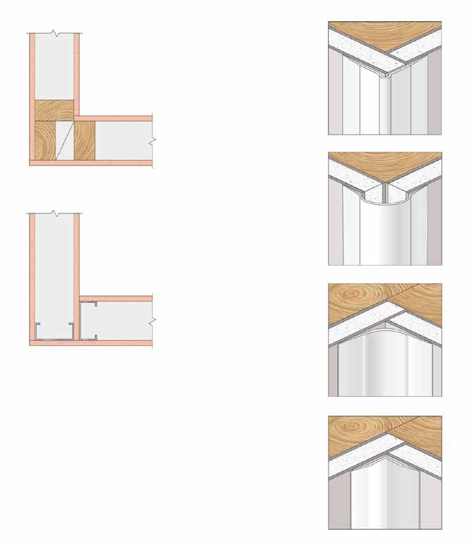
OCTOBER 2012
GIB® FIRE RATED SYSTEMS - summary table
FIRE RATED FLOOR/CEILING SYSTEMS
LOAD WEIGHT
SPECIFICATION LINING REQUIREMENTS TO UNDERSIDE OF
BEARING FRR STC IIC OF SYSTEM PAGE
REFERENCE SUPPORT FRAME
CAPABILITY (kg/m2)
GBFC 15 LB 15/15/15 38 31 Timber joists with 1 layer 13mm GIB® Standard 40 36
GBSJ 30 LB 30/30/30 34 30 Steel joists with 1 layer 13mm GIB Fyreline ®
38 37
GBFC 45 LB 45/45/45 39 32 Timber joists with 1 layer 13mm GIB Fyreline® 44 38
GBCJ30 LB 30/30/30 39 32 Composite joists with 1 layer 13mm GIB Fyreline ®
40 39
GBCJ 45 LB 45/45/45 39 32 Composite joists with 1 layer 13mm GIB Fyreline® 40 39
GBFC 60 LB 60/60/60 39 32 Timber joists with 1 layer 16mm GIB Fyreline ®
46 40
GBSJ 60 LB 60/60/60 39 32 1 layer 16mm GIB Fyreline® 40 41
GBCJ 60 LB 60/60/60 39 32 Composite joists with 1 layer 16mm GIB Fyreline ®
44 42
GBFC 90 LB 90/90/90 41 34 Timber joists with 2 layers 16mm GIB Fyreline® 63 43
GBFC 120 LB 120/120/120 – – Timber or steel joists with 2 layers 19mm GIB –
44
Fyreline®
FIRE RATED FLOOR/CEILING SYSTEMS – SUSPENDED GRID
SPECIFICATION LOAD FRR STC IIC LINING REQUIREMENTS TO UNDERSIDE OF WEIGHT PAGE
REFERENCE BEARING SUPPORT FRAME OF SYSTEM
CAPABILITY (kg/m2)
GBSC 30 LB 30/30/30 48 43 Timber joists with Rondo® Key-lock™ or 50 45
USG ScrewFix™ suspension system & 1 layer
13mm GIB Fyreline® (back blocked)
GBSC 60a LB 60/60/60 53 43 Timber joists with Rondo® Key-lock™ or 60 46
USG ScrewFix™ suspension system & 2 layers
13mm GIB Fyreline®
GBSC 60b LB 60/60/60 50 43 Timber joists with USG Drywall Grid suspension 54 47
system & 1 layer of 16mm GIB Fyreline®
GBSC 90 LB 90/90/90 53 43 Timber joists with USG Drywall Grid suspension 64 48
system & 1 layer of 13mm GIB® Fyreline® & 1 layer
of 16mm GIB Fyreline
FIRE RATED CEILING SYSTEMS - TIMBER OR STEEL FRAME
SPECIFICATION LOAD BEARING FRR LINING REQUIREMENTS TO UNDERSIDE OF SUPPORT FRAME PAGE
REFERENCE CAPABILITY
GBUC 15 LB/NLB (15)/15/15 1 layer 13mm GIB Fyreline® 49
GBUC 30 LB/NLB (30)/30/30 1 layer 16mm GIB Fyreline® 50
GBUC 45 LB/NLB (45)/45/45 2 layers 13mm GIB Fyreline ®
51
GBUC 60 LB/NLB (60)/60/60 1 layer 16mm GIB Fyreline® + 1 layer 13mm GIB Fyreline® 52
GBUC 90 LB/NLB (90)/90/90 2 layers 19mm GIB Fyreline ®
53
GBUC120 LB/NLB (120)/120/120 2 layers 19mm GIB Fyreline® 53
FIRE RATED RISERS, SHAFTS AND DUCTS
SPECIFICATION LOAD BEARING CAPABILITY FRR PAGE
REFERENCE
GIB® Fyreduct™ NLB -/30/30, -/60/60, -/90/90, -/120/120 54
GIB® Ventshaft NLB -/60/60 58
GIB Shaftwall
®
NLB -/30/30, -/60/60, -/90/90, -/120/120 61
GIB® FIRE RATED SYSTEMS
FIRE RATED STEEL BEAMS AND COLUMNS (GIB FYRELINE® LININGS ON TIMBER STRAPPING OR STEEL CLIP & CHANNEL)
FIRE RATINGS AVAILABLE PAGE
15, 30, 60, 90, 120 minutes 64-65
Note: The STC and IIC values shown for Floor/Ceiling systems and Suspended Grid Floor/Ceilings relate to bare particle board flooring without fibreglass between the joists.
In order for GIB® systems to perform as tested, all components must be installed exactly as prescribed. Substituting components produces an entirely different system and may
seriously compromise performance. Follow system specifications.
FOR FURTHER INFORMATION VISIT WWW.GIB.CO.NZ OR PHONE 0800 100 442
5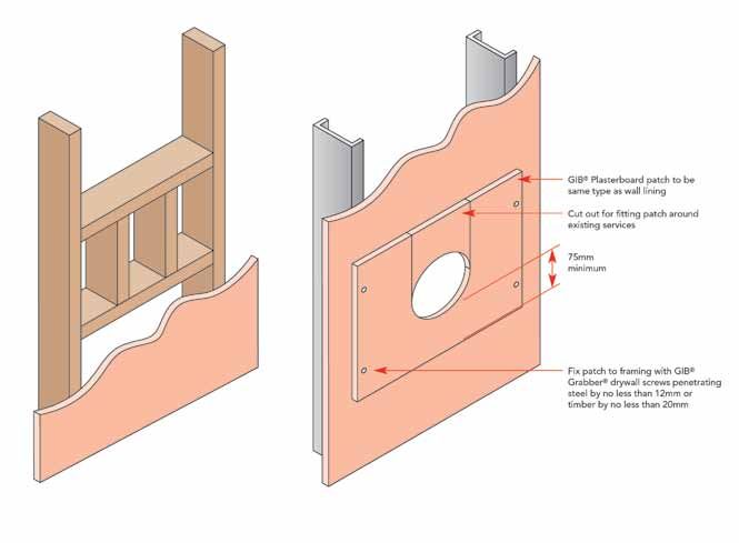
OCTOBER 2012

                                     Table of Contents
                          Introduction

                          Compliance with the New Zealand Building Code (NZBC)............................................................................................................... 7
                          Handling and Limitations ..................................................................................................................................................................... 7
                          Appraisal and Quality Control ............................................................................................................................................................. 7
                          Substitution ........................................................................................................................................................................................... 7
                          Structural Steel Members in Cavities .................................................................................................................................................. 8
                          Timber framed walls ............................................................................................................................................................................. 8
                          Steel framed walls ................................................................................................................................................................................. 8
                          Floor/Ceiling systems ........................................................................................................................................................................... 8
                          Surface Finish Properties ..................................................................................................................................................................... 8
                          Fire Resistance of Clad Walls ............................................................................................................................................................... 8.
                          Specification Reference ....................................................................................................................................................................... 9
                          Fire Resistance Rating (FRR) – example .............................................................................................................................................. 9
                          Sustainability and the environment ..................................................................................................................................................... 9

                          Fire Rated Wall Systems

                          Summary Table .............................................................................................................................................................................              4-5
                          Two Way FRR – Timber Frame .....................................................................................................................................................                       10-19
                          Two Way FRR – Steel Frame ........................................................................................................................................................                     20-28
                          Two Way FRR – Timber or Steel Frame .......................................................................................................................................                            29-30
                          One Way FRR – Timber or Steel Frame ......................................................................................................................................                             31-35

                          Fire Rated Floor/Ceiling Systems, Ceilings, Suspended Ceilings

                          Summary Table ..............................................................................................................................................................................             4-5
                          Floor/ceiling systems ..................................................................................................................................................................... 36-44
                          Suspended Grid ............................................................................................................................................................................. 45-48
                          Timber or Steel Frame Ceiling Systems ...................................................................................................................................... 49-53

                          Fire Rated Systems

                          GIB® Fyreduct™ 900 ....................................................................................................................................................................... 54-55
                          GIB® Fyreduct™ 600 ....................................................................................................................................................................... 56-57
                          GIB® Ventshaft ................................................................................................................................................................................ 58-59
                          Chase Walls .....................................................................................................................................................................................        60
                          GIB® Shaftwall ................................................................................................................................................................................. 61-63
                          Steel Columns and Beams ............................................................................................................................................................. 64-65

                          Junction Details for Fire and Smoke Separations

                          Control Joints ....................................................................................................................................................................................      66
                          Corner Junctions ..............................................................................................................................................................................          67
                          ‘T’ Junctions ......................................................................................................................................................................................     68
                          Wall – Floor/Ceiling Junctions .........................................................................................................................................................                 69
                          Drywall to Masonry Junctions ..........................................................................................................................................................                  70
                          Deflection Head Details ...................................................................................................................................................................              71
                          Suspended Ceiling to Wall Junctions .............................................................................................................................................                        72

                          Penetrations in GIB® Fire Rated Systems
GIB® FIRE RATED SYSTEMS

                          The New Zealand Building Code ....................................................................................................................................................                       73
                          General Notes ...................................................................................................................................................................................        73
                          Online Penetration Systems Listing ................................................................................................................................................                      73
                          Penetrations in GIB® Fire Rated Systems ....................................................................................................................................... 74-78
                          Propriety Penetration Seals..............................................................................................................................................................                79

                          Stability of Fire Rated Elements................................................................................................................................. 80-81

                                                                                                       FOR FURTHER INFORMATION VISIT WWW.GIB.CO.NZ OR PHONE 0800 100 442
     6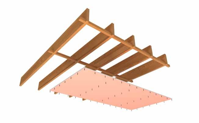
OCTOBER 2012

       Introduction
Compliance with the New Zealand                                     Handling and Limitations
Building Code (NZBC)                                                GIB® plasterboard must be stacked flat and protected from
NZBC Clause B2 – Durability                                         the weather.
Under normal conditions of dry internal use GIB® Fire Rated         GIB® plasterboard must be handled as a finishing material.
Systems have a serviceable life in excess of 50 years and
                                                                    GIB® plasterboard linings in use must not be exposed to
satisfy the requirements of NZBC Clause B2 – Durability.
                                                                    liquid water or be installed in situations where extended
NZBC Clauses C1 – C6 Protection from Fire                           exposures to humidity above 90% RH can reasonably be
GIB® Fire Rated Systems can be used to provide passive fire         expected.
protection in accordance with the requirements of NZBC              Adhesive fixing can not be used as an alternative to
Clauses C1 - C6 – Protection from Fire.                             mechanical fasteners in GIB® fire rated specifications.
NZBC Clause C6 – Structural Stability                               In normal use GIB® plasterboard must not be exposed to
In order to satisfy the requirements of this clause, designers      temperatures in excess of 52º C for prolonged periods.
must ensure that fire rated elements are supported by
elements having at least the same Fire Resistance Rating            Appraisal and Quality Control
(FRR). Collapse of elements having a lesser FRR shall not           This document has been appraised by the Building Research
cause the consequential collapse of elements required to            Association of New Zealand (BRANZ), Appraisal No. 289
have a higher FRR.                                                  [2012] GIB® Fire Rated Systems, 2012.
NZBC C/AS1 - 7 (2012) now makes clear distinction between
                                                                    The FRRs of specifications published in the document have
‘structural adequacy’ and ‘stability’. Structural adequacy is
                                                                    been obtained by independent testing or assessment
the first number in the x/x/x FRR sequence and simply relates
                                                                    sourced from organisations with accredited quality assurance.
to the ability of a specimen to resist a vertical load applied in
                                                                    It is of prime importance to comply with the details of design,
the standard furnace test for fire resistance. Stability relates
                                                                    construction and workmanship in this document.
to the support provided to a building element having a FRR.
The stability of an element having a FRR often depends on           GIB® plasterboard is manufactured to strict quality standards
other elements, such as a column supporting a floor or a            and formulations are uniform nation-wide. All GIB® branded
section of wall providing lateral support to a firecell boundary    accessory products are the subject of ongoing quality control
wall. Although the supporting element itself may not provide        to ensure consistency of supply.
firecell separation, it still needs a FRR no less than the          To allow positive identification of GIB Fyreline® on site, the
element for which it is providing stability in order to avoid       face paper of the board is coloured pink.
consequential collapse.
Simply selecting a FRR may not be appropriate when an               Substitution
element, providing stability, does not form part of a firecell      When 10mm GIB Braceline® / Noiseline®, 10mm GIB
boundary and is located entirely within a firecell. A FRR is        Ultraline®, 10mm GIB Aqualine® or 13mm GIB® Standard are
by definition a result against a standard furnace test for          substituted in place of 10mm GIB Fyreline®, the FRR of that
fire resistance where a wall or floor/ceiling specimen is           system will be maintained.
exposed from one side only. A wall located entirely within
                                                                    Similarly the FRR is maintained when 13mm GIB Braceline®
a firecell will potentially be exposed to fire from more sides
                                                                    / Noiseline®, 13mm GIB Toughline®, or 13mm GIB Aqualine®
simultaneously. In this case ‘universal’ or ‘one way’ lining
                                                                    are substituted for 13mm GIB Fyreline®.
protection may need to be provided to all relevant sides. If
the wall provides a lateral support or a bracing function and       Otherwise, achieving the FRR of GIB® Fire Rated Systems
is located within a firecell, then the bracing system must be       depends on closely following the detailed specifications.
protected with a ‘universal’ or ‘one way’ lining system.            Installation of systems outside their stated scope of
                                                                    application, or substituting components, may compromise
NZBC Clause G6 – Airborne and Impact Sound
                                                                    fire safety.
For many specifications in the technical literature Sound
Transmission Class (STC) and Impact Insulation Class (IIC)
performances are given. For higher performances, including
those required by NZBC Clause G6 – Airborne and Impact
Sound, reference should be made to the current version of
‘GIB® Noise Control Systems’.
                                                                                                                                      GIB® FIRE RATED SYSTEMS

FOR FURTHER INFORMATION VISIT WWW.GIB.CO.NZ OR PHONE 0800 100 442
                                                                                                                                           7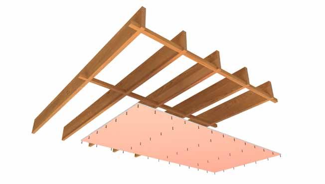
OCTOBER 2012

                                 Introduction
                          Structural Steel Members in                                          Floor/Ceiling Systems
                          Cavities                                                             Floor/ceiling systems have generally been tested for a design
                          Structural steel members are sometimes located inside the            load of 3 kPa at a span of 4 metres. For floor joist span tables
                          cavity of a GIB® fire rated system, such as a column in a wall or    consult the latest version of NZS3604 or supplier information
                          beam in a floor/ceiling cavity. The FRR of a wall or floor/ceiling   with respect to proprietary joists.
                          system applies across the entire element, from the exposed           Flooring shall be minimum 20 mm particle board complying
                          face to the un-exposed side. Temperatures inside the cavity          with AS/NZS 1860 Part 1:2002 Particleboard flooring –
                          can rise to levels above the critical temperature for some           Specifications, or minimum 17 mm plywood manufactured to
                          steel members and it can not be automatically assumed that           AS/NZS 2269 Part 0:2008 Plywood – Structural - Specifications.
                          a structural steel member achieves the structural endurance
                          rating of the cavity system within which it is contained. For        Do not increase joist or nog spacing from what has been
                          guidance on the protection of steel columns and beams                specified.
                          refer to the appropriate section of this document. For further       Do not decrease joist dimensions from what has been
                          assistance contact the GIB® Helpline 0800 100 442.                   specified.

                          Timber framed Walls                                                  Do not exceed the maximum permissible design stress.

                          Load-bearing and non load-bearing walls                              Do not substitute alternative type joist to those specified.
                          Consult the current edition of NZS3604 to determine framing
                                                                                               Surface Finish Properties
                          dimensions and wall heights for load-bearing and non
                          load-bearing walls. Beyond these limits specific engineering         All paper-faced GIB® plasterboard sheet materials have been
                          design is required.                                                  tested in accordance with ISO 5660 Reaction to Fire Tests –
                                                                                               Heat release, smoke production and mass loss rate Parts 1
                          Under no circumstances shall the framing spacing be more             and 2 and achieve a Group 1-S Classification.
                          or the timber dimensions be less than those specified for the
                          relevant GIB® specification.                                         Note that this Classification applies to the plasterboard
                                                                                               product without paint or wallpaper finish. The supplier
                          Steel Framed Walls                                                   or manufacturer of any selected surface finish must be
                          Non load-bearing walls                                               contacted for their particular product Classification when
                                                                                               applied over the relevant substrate.
                          Wall heights greater than the specified limit for the relevant
                          GIB® specification are the subject of specific design for            Fire Resistance of Clad Walls
                          serviceability and fire design criteria. Consult the framing
                                                                                               Where GIB® fire rated specifications are clad with any of the
                          supplier for serviceability criteria. For fire design criteria
                                                                                               following materials the lining may be left unstopped;
                          contact the GIB® Helpline 0800 100 442.
                                                                                               Timber or wood based products
                          Load-bearing walls
                          The solutions provided in this technical literature for load-        Steel, flat or profiled
                          bearing steel stud walls are conservatively based on limiting        Fibre cement sheets or boards
                          stud temperature. More accurate predictions can be made
                                                                                               Insulation and finish systems (EIFS).
                          if the applied stud load (at the time of the fire) and stud
                          capacity (at ambient temperature) are known, using the               As an alternative to plaster stopping, sheet joints in ceiling
                          equation:                                                            voids can be covered with a minimum 150 mm wide strip of
                                                                                               GIB® plasterboard, centrally placed over the sheet joint, and
                          FRR (LB) = FRR (NLB) x (1- Applied Load / Capacity), where;
                                                                                               screw fixed to the underlying framing at no more than 300
                          FRR (LB)         is the calculated FRR of the load-bearing wall      mm centres.
                          FRR (NLB)        is the FRR of the non load-bearing wall with        Note that any GIB® plasterboard installed on the external
                                           equivalent linings                                  face of a frame must be protected from the weather during
                          Applied Load     is the applied stud load at the time of the fire    installation and in-service. An exterior cladding over the GIB®
                                           (kN/stud)                                           plasterboard must comply with the current version of NZBC
                                                                                               E2/AS1 and be installed over a flexible wall underlay and
                          Capacity         is the stud capacity at ambient temperature         drained cavity complying with E2/AS1.
                                           (kN/stud)
                          Example:
                          A load-bearing steel frame has a capacity (ambient) of 12 kN
                          / stud and a fire design load of 4 kN / stud.
GIB® FIRE RATED SYSTEMS

                          The linings are 13mm GIB Fyreline® each side of the frame
                          installed in accordance with the equivalent non load-bearing
                          specification GBS60. The FRR of the load-bearing system can
                          be estimated as follows;
                          FRR (LB) = 60 x (1 – 4 / 12) = 60 x 2/3 = 40 minutes, or
                          FRR 40/40/40.

                                                                             FOR FURTHER INFORMATION VISIT WWW.GIB.CO.NZ OR PHONE 0800 100 442
     8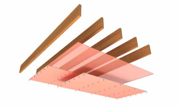
OCTOBER 2012

       Introduction

Specification Reference

  System Example

     L = Loadbearing system (notation used for loadbearing wall only)                                A = Acoustic system (notation used for specific sound
     NLB = Non loadbearing                                                                           control systems only)

     GIB® Plasterboard
                                                       GB             T          L     A        60            b                      Alternative system (a or b)

     T = Timber frame wall           UC = Universal Ceiling                                      Fire Resistance Rating (Minutes) (FRR)
     S = Steel frame wall            CJ = Composite Joists
     UW = Universal Wall
     FC = Floor/Ceiling
     SC = Suspended Ceiling

                                                                                     We will achieve our standards of performance through
  FRR Example                                                                        positive action, employee involvement and constant
                                                                                     communication with our neighbours, local authorities and
                                                                                     customers.
               -              /         30             /          30                 Winstone Wallboards is the first manufacturer of plasterboard
                                                                                     to have products certified as environmentally preferable
                                                                                     through Environmental Choice New Zealand. The
      Structural adequacy         Integrity value in       Insulation value in
                                                                                     Environmental Choice label acknowledges the product
       value in minutes (i)          minutes (ii)             minutes (iii)          as meeting or exceeding the voluntary environmental
                                                                                     declaration standard set by the New Zealand Eco-labelling
                                                                                     Trust. The standard is a comprehensive lifecycle assessment
                                                                                     which is scientifically and internationally recognised.
                                                                                     The Environmental Choice Label covers all GIB® Plasterboard
Fire Resistance Rating (FRR)                                                         13mm and greater in thickness.
i) Structural adequacy – to prevent collapse of structural                           Specify GIB® Plasterboard with the Environmental Choice
(primary) elements during a fire. Brackets, e.g. (30)/30/30                          label as this ensures that the product selected minimises
indicate that the system may be loadbearing or non-                                  the impact on the environment. Consideration should be
loadbearing depending on the design.                                                 given to minimising on-site waste when designing and/
Dash (-) indicates a nil rating, e.g. -/30/30 is NLB                                 or installing GIB® Plasterboard systems. For larger projects
                                                                                     consideration should be given to the utilisation of Winstone
ii) Integrity – To prevent the passage of flame or hot gases
                                                                                     Wallboards cut-to-length service to reduce the volume of
through the fire separations or external wall or roofs.
                                                                                     waste produced.
iii) Insulation – To prevent the transmission of heat to other
                                                                                     GIB® Plasterboard off-cuts, if separated from other waste
firecells or adjacent property.
                                                                                     building materials, can be readily recycled. For lager projects
Sustainability and the                                                               the waste can be diverted to compost manufacturers who
                                                                                     grind up the GIB® Plasterboard and use it in compost. For
Environment                                                                          smaller projects, the GIB® Plasterboard can be ground up
Winstone Wallboards is commited to protecting the                                    and spread round the building site.
environment. Environmental matters are integrated into all
business activities:                                                                 Note: A special cut to length service is available. Please call
                                                                                     the GIB® Helpline for more information on this service.
All operations of Winstone Wallboards will strive to exceed
all environmental regulatory requirements at all times.
Protection of the environment is a day to day responsibility
that we all must accept.
                                                                                                                                                                                   GIB® FIRE RATED SYSTEMS

We will allocate appropriate management time and
resources to address relevant environmental issues and
continuously improve our activities in that area.

                                                                                                                                                             Gypsum Plasterboard
                                                                                                                                                             Licence No. 1907032

FOR FURTHER INFORMATION VISIT WWW.GIB.CO.NZ OR PHONE 0800 100 442
                                                                                                                                                                                        9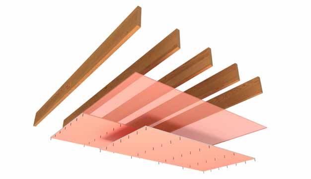
OCTOBER 2012

                                 FIRE RATED WALL SYSTEMS
                          TWO way frr - Timber Frame

                           SPECIFICATION        LOADBEARING          FIRE RESISTANCE       LINING                        SOUND                        SYSTEM WEIGHT
                           NUMBER               CAPACITY             RATING                REQUIREMENTS                  TRANSMISSION                 APPROX
                                                                                                                         CLASS
                           GBT 15               NBL                  -/15/15               1 layer 10mm GIB®             STC 36                       22kg/m2
                                                                                           Standard each side
                           GBTL 15              LB                   15/15/15

                          FRAMING                                                            FASTENING THE LINING
                          GBT15 Non Loadbearing and GBTL15 Loadbearing                       Fasteners
                          Framing to comply with;                                            41mm x 6g GIB® Grabber® High Thread Drywall Screws or
                                                                                             40mm x 2.8mm GIB® Nails.
                          • NZBC B1 – Structure: AS1 Clause 3 – Timber (NZS 3604) or
                            VM1 Clause 6 – Timber (NZS 3603)                                 Fastener Centres
                          • NZBC B2 – Durability: AS1 Clause 3.2 – Timber (NZS 3602)         300mm centres around the sheet perimeter.
                          • Studs at 600mm centres maximum                                   Place fasteners 12mm from bound sheet edges and 18mm
                          • Nogs at 1200mm centres for Horizontal fixing                     from sheet ends.

                          WALL HEIGHTS AND FRAMING                                           Single screws or nails at 300mm centres to intermediate
                          DIMENSIONS                                                         studs.

                          GBT15 Non Loadbearing – Framing dimensions and height              JOINTING
                          as determined by NZS 3604 stud tables for non loadbearing
                                                                                             All fastener heads stopped and all sheet joints tape
                          partitions.
                                                                                             reinforced and stopped in accordance with the publication
                          GBTL15 Loadbearing – Framing dimensions and height                 entitled “GIB® Site Guide”.
                          as determined by NZS 3604 stud and top plate tables for
                          loadbearing walls.

                          LINING
                          1 layer of 10mm GIB® Standard Plasterboard each side of the
                          frame.
                          Vertical or Horizontal fixing permitted. Sheets shall be touch
                          fitted.
                          When fixing vertically, full height sheets shall be used where       In order for GIB® systems to perform as tested, all components must be installed
                          possible.                                                            exactly as prescribed. Substituting components produces an entirely different
                                                                                               system and may seriously compromise performance. Follow system specifications.
                          All sheet joints must be formed over solid timber framing.

                                                                                600mm
                                                                                 max

                                                                                                                                     18mm

                                                                                                                                    300mm
GIB® FIRE RATED SYSTEMS

                                                                                                                    Single screws or nails at 300mm centres

                                                                            12mm

                                                                           FOR FURTHER INFORMATION VISIT WWW.GIB.CO.NZ OR PHONE 0800 100 442
10
OCTOBER 2012
FIRE RATED WALL SYSTEMS
two way frr - Timber Frame
SPECIFICATION LOADBEARING FIRE RESISTANCE LINING SOUND SYSTEM WEIGHT
NUMBER CAPACITY RATING REQUIREMENTS TRANSMISSION APPROX
CLASS
GBT 30a NLB -/30/30 1 layer 10mm GIB STC 36 22kg/m2
Fyreline® each side
GBTL 30 LB 30/30/30
FRAMING FASTENING THE LINING
GBT30a Non Loadbearing and GBTL30 Loadbearing Fasteners
Framing to comply with; 41mm x 6g GIB® Grabber® High Thread Drywall Screws or
40mm x 2.8mm GIB® Nails.
• NZBC B1 – Structure: AS1 Clause 3 – Timber (NZS 3604) or
VM1 Clause 6 – Timber (NZS 3603) Fastener Centres
• NZBC B2 – Durability: AS1 Clause 3.2 – Timber (NZS 3602) 300mm centres around the sheet perimeter.
• Studs at 600mm centres maximum Place fasteners 12mm from bound sheet edges and 18mm
• Nogs at 1200mm centres for Horizontal fixing from sheet ends.
WALL HEIGHTS AND FRAMING Single screws or nails at 300mm centres to intermediate
DIMENSIONS studs.
GBT30a Non Loadbearing – Framing dimensions and height JOINTING
as determined by NZS 3604 stud tables for non loadbearing
All fastener heads stopped and all sheet joints tape
partitions.
reinforced and stopped in accordance with the publication
GBTL30 Loadbearing – Framing dimensions and height entitled “GIB® Site Guide”.
as determined by NZS 3604 stud and top plate tables for
loadbearing walls.
LINING
1 layer of 10mm GIB Fyreline® each side of the frame.
Vertical or Horizontal fixing permitted.
Sheets shall be touch fitted.
When fixing vertically, full height sheets shall be used where In order for GIB® systems to perform as tested, all components must be installed
possible. exactly as prescribed. Substituting components produces an entirely different
system and may seriously compromise performance. Follow system specifications.
All sheet joints must be formed over solid timber framing.
600mm
max
18mm
300mm
GIB® FIRE RATED SYSTEMS
Single screws or nails at 300mm centres
12mm
FOR FURTHER INFORMATION VISIT WWW.GIB.CO.NZ OR PHONE 0800 100 442
11OCTOBER 2012
FIRE RATED WALL SYSTEMS
two way frr - Timber Frame
SPECIFICATION LOADBEARING FIRE RESISTANCE LINING REQUIREMENTS SOUND SYSTEM WEIGHT
NUMBER CAPACITY RATING TRANSMISSION APPROX
CLASS
GBT 30b NLB -/30/30 1 layer 13mm STC 36 26kg/m2
GIB®Standard each side
GBTL 30b LB 30/30/30
FRAMING FASTENING THE LINING
GBT30b Non Loadbearing and GBTL30b Loadbearing Fasteners
Framing to comply with, 41mm x 6g GIB® Grabber® High Thread Drywall Screws or
40mm x 2.8mm GIB® Nails.
• NZBC B1 – Structure: AS1 Clause 3 – Timber (NZS 3604) or
VM1 Clause 6 – Timber (NZS 3603) Fastener Centres
• NZBC B2 – Durability: AS1 Clause 3.2 – Timber (NZS 3602) 300mm centres around the sheet perimeter.
• Studs at 600mm centres maximum Place fasteners 12mm from bound sheet edges and 18mm
• Nogs at 1200mm centres for Horizontal fixing from sheet ends.
WALL HEIGHTS AND FRAMING Single screws or nails at 300mm centres to intermediate
DIMENSIONS studs.
GBT30b Non Loadbearing – Framing dimensions and height JOINTING
as determined by NZS 3604 stud tables for non loadbearing
All fastener heads stopped and all sheet joints tape
partitions.
reinforced and stopped in accordance with the publication
GBTL30b Loadbearing – Framing dimensions and height entitled “GIB® Site Guide”.
as determined by NZS 3604 stud and top plate tables for
loadbearing walls.
LINING
1 layer of 13mm GIB® Standard Plasterboard each side of the
frame.
Vertical or Horizontal fixing permitted.
Sheets shall be touch fitted.
When fixing vertically, full height sheets shall be used where In order for GIB® systems to perform as tested, all components must be installed
possible. exactly as prescribed. Substituting components produces an entirely different
system and may seriously compromise performance. Follow system specifications.
All sheet joints must be formed over solid timber framing.
600mm
max
18mm
300mm
GIB® FIRE RATED SYSTEMS
Single screws or nails at 300mm centres
12mm
FOR FURTHER INFORMATION VISIT WWW.GIB.CO.NZ OR PHONE 0800 100 442
12OCTOBER 2012
FIRE RATED WALL SYSTEMS
two way frr - Timber Frame
SPECIFICATION LOADBEARING FIRE RESISTANCE LINING SOUND SYSTEM WEIGHT
NUMBER CAPACITY RATING REQUIREMENTS TRANSMISSIOsN APPROX
CLASS
GBT 60a NLB -/60/60 1 layer 13mm GIB STC 36 27kg/m2
Fyreline® each side
GBTL 60 LB 60/60/60
FRAMING FASTENING THE LINING
Framing to comply with, Fasteners
• NZBC B1 – Structure: AS1 Clause 3 – Timber (NZS 3604) or 41mm x 6g GIB® Grabber® High Thread Drywall Screws or
VM1 Clause 6 – Timber (NZS 3603) 40mm x 2.8mm GIB® Nails.
• NZBC B2 – Durability: AS1 Clause 3.2 – Timber (NZS 3602) Fastener Centres
• Studs at 600mm centres maximum 300mm centres around the sheet perimeter.
• Nogs at 1200mm centres for Horizontal fixing
Place fasteners 12mm from bound sheet edges and 18mm
WALL HEIGHTS AND FRAMING from sheet ends.
DIMENSIONS Single screws or nails at 300mm centres to intermediate
GBT60a Non Loadbearing – Framing dimensions and height studs.
as determined by NZS 3604 stud tables for non loadbearing
partitions. JOINTING
All fastener heads stopped and all sheet joints tape
GBTL60 Loadbearing – Framing dimensions and height
reinforced and stopped in accordance with the publication
as determined by NZS 3604 stud and top plate tables for
entitled “GIB® Site Guide”.
loadbearing walls.
LINING
1 layer of 13mm GIB Fyreline® each side of the frame.
Vertical or Horizontal fixing permitted.
Sheets shall be touch fitted.
When fixing vertically, full height sheets shall be used where In order for GIB® systems to perform as tested, all components must be installed
possible. exactly as prescribed. Substituting components produces an entirely different
system and may seriously compromise performance. Follow system specifications.
All sheet joints must be formed over solid timber framing.
600mm
max
18mm
300mm
GIB® FIRE RATED SYSTEMS
Single screws or nails at 300mm centres
12mm
FOR FURTHER INFORMATION VISIT WWW.GIB.CO.NZ OR PHONE 0800 100 442
13OCTOBER 2012
FIRE RATED WALL SYSTEMS
two way frr - Timber Frame
SPECIFICATION LOADBEARING FIRE RESISTANCE LINING SOUND SYSTEM WEIGHT
NUMBER CAPACITY RATING REQUIREMENTS TRANSMISSION APPROX
CLASS
GBTL 60b LB 60/60/60 2 layers 10mm GIB STC 42 39kg/m2
Fyreline® each side
FRAMING FASTENING THE LINING
Framing to comply with, Fasteners
• NZBC B1 – Structure: AS1 Clause 3 – Timber (NZS 3604) or INNER LAYER: 41mm x 6g GIB® Grabber® High Thread
VM1 Clause 6 – Timber (NZS 3603) Drywall Screws or 40mm x 2.8mm GIB® Nails.
• NZBC B2 – Durability: AS1 Clause 3.2 – Timber (NZS 3602) OUTER LAYER: 51mm x 7g screws as above.
• Studs at 600mm centres maximum
Fastener Centres
• Nogs at 1200mm centres for Horizontal fixing
INNER LAYER: 600mm centres horizontally.
WALL HEIGHTS AND FRAMING 800mm centres vertically up each stud.
DIMENSIONS
OUTER LAYER: 300mm centres around the sheet perimeter.
Framing dimensions and height as determined by NZS 3604
stud and top plate tables for loadbearing walls. Place fasteners 12mm from bound sheet edges and 18mm
from sheet ends.
LINING Single screws at 300mm centres to intermediate studs.
2 layers of 10mm GIB Fyreline® each side of the frame.
JOINTING
Vertical or Horizontal fixing permitted.
INNER LAYER: Unstopped.
Sheets shall be touch fitted.
OUTER LAYER: All fastener heads stopped and all sheet
When fixing vertically, full height sheets shall be used where joints tape reinforced and stopped in accordance with the
possible. publication entitled “GIB® Site Guide”.
Vertical joints of the second layer are staggered from joints in
the first layer on the same side of the frame.
When sheet end butts joints are unavoidable, they must be In order for GIB® systems to perform as tested, all components must be installed
formed over solid framing and staggered. exactly as prescribed. Substituting components produces an entirely different
system and may seriously compromise performance. Follow system specifications.
All sheet joints must be formed over solid timber framing.
600mm
max 600mm
18mm
300mm
GIB® FIRE RATED SYSTEMS
Single screws or nails at 300mm centres
12mm
FOR FURTHER INFORMATION VISIT WWW.GIB.CO.NZ OR PHONE 0800 100 442
14OCTOBER 2012
FIRE RATED WALL SYSTEMS
two way frr - Timber Frame
SPECIFICATION LOADBEARING FIRE RESISTANCE LINING SOUND SYSTEM WEIGHT
NUMBER CAPACITY RATING REQUIREMENTS TRANSMISSION APPROX
CLASS
GBT 90 NLB -/90/90 1 layer 16mm GIB STC 37 36kg/m2
Fyreline® each side
GBTL 90 LB 90/90/90
FRAMING FASTENING THE LINING
Framing to comply with, Fasteners
• NZBC B1 – Structure: AS1 Clause 3 – Timber (NZS 3604) or 51mm x 7g GIB® Grabber® High Thread Drywall Screws.
VM1 Clause 6 – Timber (NZS 3603)
Fastener Centres
• NZBC B2 – Durability: AS1 Clause 3.2 – Timber (NZS 3602)
300mm centres around the sheet perimeter.
• Studs at 600mm centres maximum
Place fasteners 12mm from bound sheet edges and 18mm
• Nogs at 1200mm centres for Horizontal fixing
from sheet ends.
WALL HEIGHTS AND FRAMING Single screws at 300mm centres to intermediate studs.
DIMENSIONS
GBT90 Non Loadbearing – Framing dimensions and height JOINTING
as determined by NZS 3604 stud tables for non loadbearing All fastener heads stopped and all sheet joints tape
partitions. reinforced and stopped in accordance with the publication
entitled “GIB® Site Guide”.
GBTL90 Loadbearing – Framing dimensions and height
as determined by NZS 3604 stud and top plate tables for
loadbearing walls.
LINING
1 layer of 16mm GIB Fyreline® each side of the frame.
Vertical or Horizontal fixing permitted.
Sheets shall be touch fitted.
When fixing vertically, full height sheets shall be used where In order for GIB® systems to perform as tested, all components must be installed
possible. exactly as prescribed. Substituting components produces an entirely different
system and may seriously compromise performance. Follow system specifications.
All sheet joints must be formed over solid timber framing.
600mm
max
18mm
300mm
GIB® FIRE RATED SYSTEMS
Single screws or nails at 300mm centres
12mm
FOR FURTHER INFORMATION VISIT WWW.GIB.CO.NZ OR PHONE 0800 100 442
15OCTOBER 2012
FIRE RATED WALL SYSTEMS
two way frr - Timber Frame
SPECIFICATION LOADBEARING FIRE RESISTANCE LINING SOUND SYSTEM WEIGHT
NUMBER CAPACITY RATINGs REQUIREMENTS TRANSMISSION APPROX
CLASS
GBT120a NLB -/120/120 2 layers 13mm GIB STC 43 47kg/m2
Fyreline® each side
FRAMING FASTENING THE LINING
Framing to comply with, Fasteners
• NZBC B1 – Structure: AS1 Clause 3 – Timber (NZS 3604) INNER LAYER: 51mm x 7g GIB® Grabber® High Thread
or VM1 Clause 6 – Timber (NZS 3603) Drywall Screws.
• NZBC B2 – Durability: AS1 Clause 3.2 – Timber (NZS 3602) OUTER LAYER: 63mm x 8g GIB® Grabber® Self Tapping
• Studs at 600mm centres maximum Screws.
• Nogs at 800mm centres maximum Fastener Centres
WALL HEIGHTS AND FRAMING INNER LAYER: 600mm centres horizontally.
DIMENSIONS 800mm centres vertically up each stud
Framing dimensions and height as determined by NZS 3604 OUTER LAYER: 300mm centres around the sheet perimeter.
stud tables for non loadbearing walls.
Place fasteners 12mm from bound sheet edges and 18mm
LINING from sheet ends.
2 layers of 13mm GIB Fyreline® each side of the frame. Single screws at 300mm centres to intermediate studs.
Vertical fixing only permitted. Full height sheets shall be used
where possible.
JOINTING
INNER LAYER: Unstopped.
Sheets shall be touch fitted.
OUTER LAYER: All fastener heads stopped and all sheet
Vertical joints of the second layer are staggered from joints in
joints tape reinforced and stopped in accordance with the
the first layer on the same side of the frame.
publication entitled “GIB® Site Guide”.
When sheet end butt joints are unavoidable, they must
be formed over solid framing with those of the first layer In order for GIB® systems to perform as tested, all components must be installed
exactly as prescribed. Substituting components produces an entirely different
staggered from those of the second layer.
system and may seriously compromise performance. Follow system specifications.
All sheet joints must be formed over solid timber framing.
600mm 600mm
max
18mm
300mm
GIB® FIRE RATED SYSTEMS
800mm max
Single screws or nails at 300mm centres
12mm
FOR FURTHER INFORMATION VISIT WWW.GIB.CO.NZ OR PHONE 0800 100 442
16OCTOBER 2012
FIRE RATED WALL SYSTEMS
two way frr - Timber Frame
SPECIFICATION LOADBEARING FIRE RESISTANCE LINING SOUND SYSTEM WEIGHT
NUMBER CAPACITY RATING REQUIREMENTS TRANSMISSION APPROX
CLASS
GBT 120b NLB -/120/120 1 layer 19mm GIB STC 35 43kg/m2
Fyreline® each side
FRAMING FASTENING THE LINING
Framing to comply with, Fasteners
• NZBC B1 – Structure: AS1 Clause 3 – Timber (NZS 3604) or 51mm x 7g GIB® Grabber® High Thread Drywall Screws.
VM1 Clause 6 – Timber (NZS 3603)
Fastener Centres
• NZBC B2 – Durability: AS1 Clause 3.2 – Timber (NZS 3602)
300mm centres around the sheet perimeter.
• Studs at 600mm centres maximum
Place fasteners 12mm from bound sheet edges and 18mm
• Nogs at 1200mm centres for Horizontal fixing
from sheet ends.
WALL HEIGHTS AND FRAMING Single screws at 300mm centres to intermediate studs.
DIMENSIONS
Framing dimensions and height as determined by NZS 3604 JOINTING
stud tables for non loadbearing walls. All fastener heads stopped and all sheet joints tape
reinforced and stopped in accordance with the publication
LINING entitled “GIB® Site Guide”.
1 layer of 19mm GIB Fyreline® each side of the frame.
Vertical or horizontal fixing permitted.
Sheets shall be touch fitted.
When fixing sheets vertically, full height sheets shall be used In order for GIB® systems to perform as tested, all components must be installed
where possible. exactly as prescribed. Substituting components produces an entirely different
system and may seriously compromise performance. Follow system specifications.
All sheet joints must be formed over.
600mm
max
18mm
300mm
GIB® FIRE RATED SYSTEMS
Single screws or nails at 300mm centres
12mm
FOR FURTHER INFORMATION VISIT WWW.GIB.CO.NZ OR PHONE 0800 100 442
17OCTOBER 2012
FIRE RATED WALL SYSTEMS
two way frr - Timber Frame
SPECIFICATION LOADBEARING FIRE RESISTANCE LINING SOUND SYSTEM WEIGHT
NUMBER CAPACITY RATING REQUIREMENTS TRANSMISSION APPROX
CLASS
GBTL 120 LB 120/120/120 2 layers 16mm GIB STC 46 65kg/m2
Fyreline® each side
FRAMING FASTENING THE LINING
Framing to comply with, Fasteners
• NZBC B1 – Structure: AS1 Clause 3 – Timber (NZS 3604) or INNER LAYER: 51mm x 7g GIB® Grabber® High Thread
VM1 Clause 6 – Timber (NZS 3603) Drywall Screws.
• NZBC B2 – Durability: AS1 Clause 3.2 – Timber (NZS 3602) OUTER LAYER: 63mm x 8g GIB® Grabber® Self Tapping
• Studs at 600mm centres maximum Screws.
• Nogs at 800mm centres maximum Fastener Centres
WALL HEIGHTS AND FRAMING INNER LAYER: 600mm centres vertically up each stud 400mm
DIMENSIONS centres horizontally along top and bottom plates.
Framing dimensions and height as determined by NZS 3604 OUTER LAYER: 300mm centres around the sheet perimeter.
stud and top plate tables for loadbearing walls. Place fasteners 12mm from bound sheet edges and 18mm
from sheet ends.
LINING
Single screws at 300mm centres to intermediate studs.
2 layers of 16mm GIB Fyreline® each side of the frame.
Vertical fixing only permitted. JOINTING
Sheets shall be touch fitted. INNER LAYER: Unstopped
Full height sheets shall be used where possible. OUTER LAYER: All fastener heads stopped and all sheet
joints tape reinforced and stopped in accordance with the
When sheet end butt joints are unavoidable, they must be
publication entitled “GIB® Site Guide”.
formed over solid framing and staggered from horizontal
joints in the first layer.
Joints of the outer layer are staggered from sheet end butt In order for GIB® systems to perform as tested, all components must be installed
joints in the first layer. exactly as prescribed. Substituting components produces an entirely different
system and may seriously compromise performance. Follow system specifications.
All sheet joints must be formed over solid timber framing.
600mm
max
18mm
300mm
GIB® FIRE RATED SYSTEMS
600mm max
Single screws or nails at 300mm centres
400mm
12mm
FOR FURTHER INFORMATION VISIT WWW.GIB.CO.NZ OR PHONE 0800 100 442
18OCTOBER 2012
FIRE RATED WALL SYSTEMS
two way frr - Timber Frame
SPECIFICATION LOADBEARING FIRE RESISTANCE LINING SOUND SYSTEM WEIGHT
NUMBER CAPACITY RATING REQUIREMENTS TRANSMISSION APPROX
CLASS
GBT 180 NLB -/180/180 2 layers 16mm GIB STC 46 65kg/m2
Fyreline® each side
FRAMING FASTENING THE LINING
Framing to comply with, Fasteners
• NZBC B1 – Structure: AS1 Clause 3 – Timber (NZS 3604) or INNER LAYER: 51mm x 7g GIB® Grabber® High Thread
VM1 Clause 6 – Timber (NZS 3603) Drywall Screws.
• NZBC B2 – Durability: AS1 Clause 3.2 – Timber (NZS 3602). OUTER LAYER: 63mm x 8g GIB® Grabber® Self Tapping Screws.
• Studs at 600mm centres maximum
Fastener Centres
• Nogs at 800mm centres maximum
INNER LAYER: 600mm centres horizontally.
WALL HEIGHTS AND FRAMING 800mm centres vertically up each stud.
DIMENSIONS
OUTER LAYER: 150mm centres around the sheet perimeter.
Framing dimensions and height as determined by NZS 3604
stud tables for non loadbearing walls. Place fasteners 12mm from bound sheet edges and 18mm
from sheet ends.
LINING Single screws at 300mm centres to intermediate studs and to
2 layers of 16mm GIB Fyreline® each side of the frame. the centre of each nog.
Vertical fixing only permitted. Full height sheets shall be used JOINTING
where possible.
FIRST LAYER: Unstopped
Sheets shall be touch fitted.
OUTER LAYER: All fastener heads stopped and all sheet
Vertical joints of the second layer are staggered from joints in joints tape reinforced and stopped in accordance with the
the first layer on the same side of the frame. publication entitled “GIB® Site Guide”.
When sheet end butt joints are unavoidable, they must be
In order for GIB® systems to perform as tested, all components must be installed
formed over solid framing with those of the first layer.
exactly as prescribed. Substituting components produces an entirely different
system and may seriously compromise performance. Follow system specifications.
600mm 600mm
max
18mm
150mm
800mm max
GIB® FIRE RATED SYSTEMS
800mm max
Single screws or nails at 300mm centres
12mm
FOR FURTHER INFORMATION VISIT WWW.GIB.CO.NZ OR PHONE 0800 100 442
19OCTOBER 2012
FIRE RATED WALL SYSTEMS
two way frr - steel Frame
SPECIFICATION LOADBEARING FIRE RESISTANCE LINING SOUND SYSTEM WEIGHT
NUMBER CAPACITY RATING REQUIREMENTS TRANSMISSION APPROX
CLASS
GBSL 15 LB 15/15/15 1 layer 13mm STC 34 22kg/m2
GIB®Standard each side
FRAMING AND WALL HEIGHT FASTENING THE LINING
Any steel frame designed to meet structural criteria for Fasteners
strength and serviceability under dead and live loads. 25mm x 6g GIB® Grabber® Drywall Self Tapping Screws.
Stud width shall be 35mm minimum. Fastener Centres
Stud spacing at 600mm centres maximum. Frame height as 300mm centres up each stud.
determined by specific design.
Place fasteners 12mm from sheet edges generally and 50mm
LINING from sheet ends.
1 layer of 13mm GIB® Standard Plasterboard each side of the JOINTING
frame.
All screw heads stopped and all sheet joints tape reinforced
Vertical fixing. Full height sheets shall be used where and stopped in accordance with the publication entitled
possible. “GIB® Site Guide”.
Horizontal fixing is permitted as long as all longitudinal sheet Note: See also page 8, “Loadbearing Steel Framed Walls”.
joints are formed over nogs.
Sheets shall be touch fitted.
Offset joints between sheets on opposite sides of the frame.
When sheet end butt joints are unavoidable, they shall be
fixed at 200mm centres and formed over nogs.
In order for GIB® systems to perform as tested, all components must be installed
All sheet joints must be formed over framing. exactly as prescribed. Substituting components produces an entirely different
system and may seriously compromise performance. Follow system specifications.
Linings are fixed hard to floor.
600mm
max
50mm
300mm
GIB® FIRE RATED SYSTEMS
Offset joints between sheets
12mm on opposite sides of the frame
FOR FURTHER INFORMATION VISIT WWW.GIB.CO.NZ OR PHONE 0800 100 442
20OCTOBER 2012
FIRE RATED WALL SYSTEMS
two way frr - steel Frame
SPECIFICATION LOADBEARING FIRE RESISTANCE LINING SOUND SYSTEM WEIGHT
NUMBER CAPACITY RATING REQUIREMENTS TRANSMISSION APPROX
CLASS
GBS 30 NLB -/30/30 1 layer 13mm STC 34 22kg/m2
GIB®Standard each side
FRAMING AND WALL HEIGHT When sheet end butt joints are unavoidable, they shall be
formed over nogs.
Steel stud dimensions to be 64 x 34 x 0.55mm nominal with a
6mm return. All sheet joints must be formed over framing.
Steel track dimensions to be 64 x 30 x 0.55mm nominal. Linings are fixed hard to floor.
Top and bottom tracks are fixed to the floor and ceiling in FASTENING THE LINING
true alignment.
Fasteners
Stud spacing at 600mm centres maximum.
25mm x 6g GIB® Grabber® Drywall Self Tapping Screws.
Place studs to allow a 15mm expansion gap at the top of the
Fastener Centres
frame.
300mm centres up each stud.
The studs are held in place by the “grip” of the channel
runners. Light locating fasteners that fail at high Place fasteners 12mm from sheet edges generally and 50mm
temperatures, such as single aluminium rivets may be used. from sheet ends.
Otherwise positive fixing must be avoided. Fastening the linings to top and bottom tracks is permitted
Recommended maximum height of partition is 2700mm. as long as the fasteners do not connect the studs and tracks.
Higher walls are the subject of specific engineering design. SERVICES
Note: If lighter BMT steel studs are used, verification of performance Holes may be drilled or pre-punched in the metal studs to allow
must be obtained from the supplier of the framing system. installation of electrical service lines and plumbing supply pipes.
LINING JOINTING
1 layer of 13mm GIB Standard Plasterboard each side of the
®
All screw heads stopped and all sheet joints tape reinforced
frame. and stopped in accordance with the publication entitled
Vertical fixing only permitted. “GIB® Site Guide”.
Sheets shall be touch fitted.
In order for GIB® systems to perform as tested, all components must be installed
Offset joints between sheets on opposite sides of the frame. exactly as prescribed. Substituting components produces an entirely different
Full height sheets shall be used where possible. system and may seriously compromise performance. Follow system specifications.
600mm Studs placed to allow a
max 15mm expansion gap at
the top of the frame
50mm
300mm
GIB® FIRE RATED SYSTEMS
Offset joints between sheets
12mm on opposite sides of the frame
FOR FURTHER INFORMATION VISIT WWW.GIB.CO.NZ OR PHONE 0800 100 442
21You can also read