INTERTENANCY TERRACED HOUSING SYSTEMS - KOROK - KOROK ...
←
→
Page content transcription
If your browser does not render page correctly, please read the page content below
KOROK®

INTERTENANCY
TERRACED HOUSING
SYSTEMS

CBI 5171
FEBRUARY 2021   KOROK
KOROK®

INTERTENANCY
TERRACED HOUSING
SYSTEMS

SECURE, QUIET,                                                QUIET
                                                              KOROK® panels offer superior mass over traditional
FLEXIBLE.                                                     timber and plasterboard or equivalent systems resulting
Multi-unit construction projects, such as town houses, call   in enhanced sound attenuation, particularly in the more
for well-tested technology that’s simple to install. KOROK®   invasive lower frequencies. This means that residents are
Intertenancy wall offers the benefits of proven fire and      comfortable in their own space without the intrusion of noise
acoustic performance, and the security of a solid wall        from other dwellings.
design.
                                                              FLEXIBLE
SECURE                                                        Because KOROK® panels provide all the fire protection you
KOROK® panels consist of a steel shell filled with aerated    need, you can run electrical and plumbing services on the
concrete. Having a solid wall provides peace of mind          inter-tenancy wall, without the need for special penetration
to occupants’ in the knowledge that they are physically       seals around each pipe or light switch. This allows you the
separated from neighbouring dwellings.                        flexibility of placing a TV and kitchen where you want, and
                                                              the ability to hang pictures on the wall without compromising
                                                              the fire and acoustic resistance of the Inter-tenancy wall.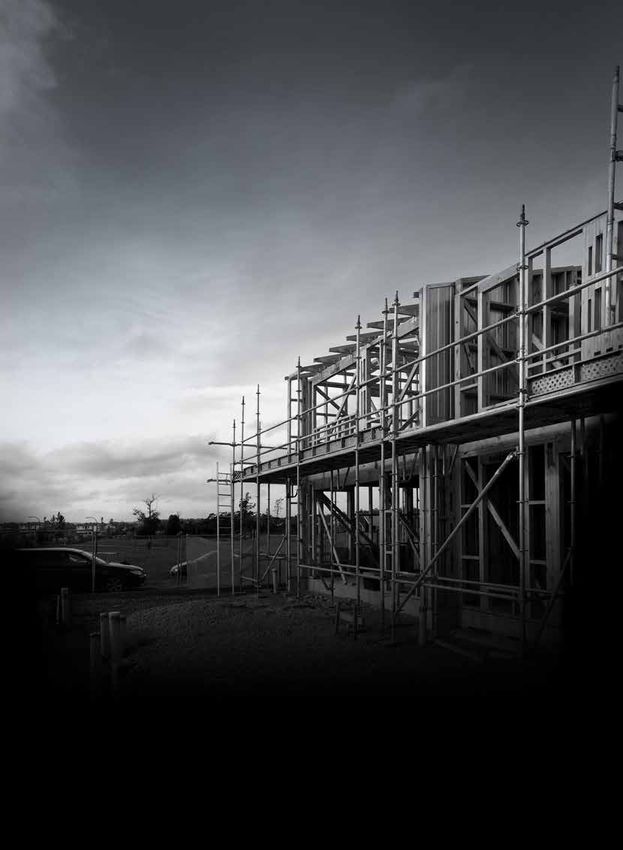
Due to its unique composition, KOROK® provides
 This manual has been developed using                   exceptional fire resistance over a long period of
 recognised Australian and New Zealand                  time.
 Standards together with sound engineering
 principles substantiated through BRANZ.                However, to achieve the stated fire resistance
                                                        ratings, it is critically important to adhere strictly
 This manual in no way supersedes the                   to the design, installation and construction
 requirements of any Statutory Authority or New         details otherwise the fire resistance rating may be
 Zealand Building Code but is rather a guide            degraded.
 to the performance of KOROK® under certain
 loading conditions.                                    KOROK® panels have been tested and appraised by
                                                        the Building Research Association of New Zealand
 The manual provides builders, engineers,               (BRANZ). In some cases, a fire resistance rating
 designers and architects with a user-friendly          has been based on an appraisal from the same
 format for installing and designing KOROK® for         organisation.
 non-load bearing applications.
                                                        Where specific acoustic control performance is
 In brief, KOROK® has:                                  required, KOROK® can provide a number of proven,
 • Fire rated systems ranging from 30 minutes           acoustic-rated wall systems, or can assist in
   to 240 minutes.                                      developing a fully customised solution.
 • Acoustic systems ranging from STC 36 to
   STC 76.
 • Panel dimensions of 250mm wide, in lengths
   up to 9.3 metres.
 • Panels that weigh (nominally) 10.2kg per
   lineal metre.
 • Panels available in galvanised or colour steel.
 Typical Applications are:
 • Dividing and boundary walls for sheds,
   factories and warehouses.
 • Cinema walls.
 • Intertenancy walls for apartments, terraced
   housing, hotels and retirement complexes.
 • Lift shaft and duct walls.
 • Acoustic barriers.

             Appraisal No.1059 [2019]

KOROK® INTERTENANCY TERRACED HOUSING SYSTEMS www.korok.com 0800 773 777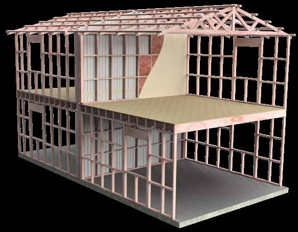
CONTENTS
INTRODUCTION                                                                                                                1      TERRACED HOUSING INTERTENANCY
                                                                                                                                   SYSTEMS INSTALLATION                                                                                          17
Acoustic performance..................................................................................1
Fire performance.............................................................................................1                     Table 2 - Screw Placement wall panels............................................23
100% reusable, minimum waste.............................................................1                                         Final check........................................................................................................23
Use only the Current Specification........................................................2                                        Roof Intersection..........................................................................................24
Beware of Substitutions...............................................................................2                            Roof Intersection..........................................................................................25
Purpose.................................................................................................................2          Roof Intersection Mineral Wool Top Track......................................26
Scope of Use.....................................................................................................2                 Floor Intersection.........................................................................................27
Transport .............................................................................................................3           Clad Wall Intersection Solid Block.......................................................28
Handling and Storage...................................................................................3                           External Corner Solid Blocking.............................................................29
On Site Handling and Storage .................................................................3                                    Wall Projection at External Timber Frame Wall.............................30
Cleaning................................................................................................................3          Clad Wall Corner Intersection................................................................31
Strippable Film..................................................................................................3                 External Solid Blocking..............................................................................32
Cutting of KOROK® Panels.........................................................................3
Installation............................................................................................................3          TABLE 3 - KOROK® FASTENERS SPACING                                                                            33
Definitions ...........................................................................................................3
                                                                                                                                   PANEL PROPERTIES                                                                                              34
STRUCTURAL                                                                                                                  4
                                                                                                                                   KOROK® panels.............................................................................................34
Maximum Permissible Height...................................................................4                                     Loading combinations...............................................................................34
Mid-wall horizontal joints.............................................................................4                           General design notes.................................................................................34
Support Bracket Separation......................................................................4                                  References.......................................................................................................34
Framing..................................................................................................................5         Standards..........................................................................................................34
Timber Framing.................................................................................................5                   Manufacturers documents......................................................................34
Steel Framing.....................................................................................................5
                                                                                                                                   KOROK® COMPONENTS SUMMARY                                                                                     35
DESIGN CONSIDERATIONS                                                                                                       5
Fire ..........................................................................................................................5   SUSTAINABILITY                                                                                                39
Acoustic Performance ................................................................................5
Plasterboard Fixing Instructions..............................................................5
What is KOROK® Intertenancy Wall?.....................................................6
Benefits.................................................................................................................7
How the System Works................................................................................7
West Auckland fire..........................................................................................8

KOROK® TERRACED HOUSING INTERTENANCY
SYSTEMS                              9
Table 1 - Systems Summary Table........................................................9
KIT01 - 60/60/60..........................................................................................11
KIT01A - 60/60/30.......................................................................................12
KIT04 - 60/60/60..........................................................................................13
KIT06 - 120/120/120.................................................................................14
KIT06A - 120/120/60.................................................................................15
KIT09 - 120/120/60....................................................................................16

                                                                                            KOROK® INTERTENANCY TERRACED HOUSING SYSTEMS www.korok.com 0800 773 777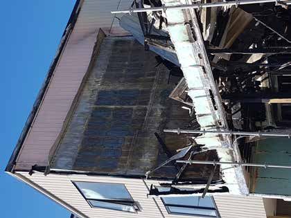
INTRODUCTION

   SUPERIOR FIRE AND ACOUSTIC PERFORMANCE WITH CLIP-TOGETHER SIMPLICITY

           •    BRANZ appraised
           •    Roll formed galvanised steel or colour
                steel outer shell
           •    Lightweight with an aerated concrete
                core
           •    Fire ratings up to -/240/240
           •    Acoustic ratings up to STC 76
           •    Panels interlock with clip-together
                simplicity for rapid installation
           •    Can be dismantled and reassembled to
                accommodate changing requirements
           •    Can be installed horizontally or vertically

When acoustic and fire regulations demand a high                 FIRE PERFORMANCE
performance, no-risk solution, KOROK® will exceed New
                                                                KOROK® delivers proven two-way fire resistance over a long
Zealand Building Code requirements for internal and external
                                                                period of time. KOROK® has been tested and appraised by
non-load bearing walls simply and cost effectively.
                                                                the Building Research Association of New Zealand (BRANZ).
Exceptionally strong yet lightweight, the interlocking panels
                                                                FRR ratings are based on the KOROK® panel wall. The cavity
can be easily erected by a small crew, making KOROK® much
                                                                and linings contribute to the STC rating but are not relevant
faster to install than conventional wall systems.
                                                                to the stated FRR.
Construction using KOROK® allows a building to be made
weather resistant much earlier in the construction cycle        100% REUSABLE, MINIMUM WASTE
allowing internal work and finishing to be started sooner.       KOROK® is manufactured in New Zealand and offers unique
                                                                benefits in terms of sustainability and environmental
ACOUSTIC PERFORMANCE                                            performance:
KOROK®’s inherent mass and interlocking design gives it
                                                                •   Walls can be reused by simply dismantling the panels
outstanding acoustic reduction properties making it highly
                                                                    and reinstalling them in another location.
suitable in buildings where acoustic performance is critical,
such as cinemas, lecture theatres, apartments, recording        •   The raw components (steel and concrete) are 100%
studios and industrial/commercial intertenancy situations.          recyclable.
The unique interlocking design eliminates the risk of sound     •   Panels are custom manufactured to size, minimising
“leaks” between panels, and makes installation much faster          waste at the factory and on the construction site.
and more simple than traditional systems.
                                                                •   DECLARE - KOROK has Declare Certification for our
                                                                    panels, the most accessed sustainability certification
                                                                    in the building industry https://living-future.org/declare-
                                                                    products/korok. See page 39.

KOROK® INTERTENANCY TERRACED HOUSING SYSTEMS www.korok.com 0800 773 777                                                .1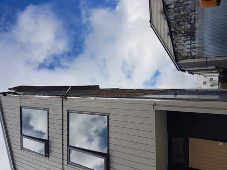
INTRODUCTION
USE ONLY THE CURRENT                                              SCOPE OF USE
SPECIFICATION                                                     New Zealand Building Code (NZBC) compliance
This publication may be superseded by a new publication.          The NZBC sets out both the legal minimum sound
KOROK® Building Systems NZ Ltd accepts no liability for           transmission between tenancies (Clause G6) and minimum
reliance upon publications that have been superseded. If          levels of fire resistance (Clauses C3 and C6). The KOROK®
you are unsure whether this is the current publication, visit     Intertenancy Systems Manual provides guidance on the
www.korok.com or call 0800 773 777.                               specification and construction of systems that will both
                                                                  meet and exceed those minimum levels. However, designers
This may be freely copied (in full) or reproduced (in full) and
                                                                  must consider the comfort of occupants when selecting a
is available by contacting us at KOROK® on 0800 773 777 or
                                                                  system that will satisfy the occupants’ expectations when
info@korok.com, or from www.korok.com
                                                                  using the space rather than the minimum required by law.

BEWARE OF SUBSTITUTIONS                                           NZBC Clause B1 – Structure
                                                                  The KOROK® Systems meet the requirements for loads
All KOROK® systems have been designed and tested to
                                                                  arising from self-weight, earthquake, wind, impact and creep
ensure they are suitable for New Zealand conditions and
                                                                  and shrinkage.
provide specific resistance to fire and acoustic transmission.
                                                                  NZBC Clause B2 – Durability
As such, only tested KOROK® panels and components
                                                                  Under normal conditions of dry internal use KOROK®
can be used in the construction of each KOROK® system,
                                                                  Intertenancy Systems have a serviceable life in excess of
ensuring that the finished wall will meet its performance
                                                                  50 years and satisfy the requirements of NZBC Clause B2 –
specification
                                                                  Durability.
                                                                  NZBC Clause C3 - Fire affecting areas beyond the
PURPOSE                                                           source
KOROK® provide intertenancy systems that physically               KOROK® Intertenancy Systems can be used to provide
separate spaces, providing secure divisional walls and            passive fire protection in accordance with the requirements
intertenancy sound and fire transmission resistance.              of NZBC Clause 3 – Spread of fire
KOROK® supplies separate systems for residential and              NZBC Clause C6 - Structural Stability
apartment intertenancy walls. Please ensure that the system       Compliance with (NZBC) Clause C6 ‘ Structural Stability’.
selected is identified as being appropriate for the location it
is being installed in.                                            In order to satisfy the requirements of the New Zealand
                                                                  Building Code (clause 6) relating to “structural stability”
                                                                  designers must ensure that KOROK® elements are
                                                                  supported by primary elements that have at least the same
                                                                  fire rating as the KOROK® system that is used.
                                                                  Where the primary elements supporting the KOROK®
                                                                  system are outside the fire cell, there is no requirement
                                                                  to apply the same FRR as the KOROK® system.
                                                                  Notwithstanding, post fire stability requirements of the NZBC
                                                                  must also be satisfied.
                                                                  NZBC Clause G6 – Airborne and Impact Sound
                                                                  KOROK® Intertenancy Systems, both meet and exceed
                                                                  the minimum requirements outlined in NZBC Clause
                                                                  G6. Consideration must be given to both the minimum
                                                                  requirements and the comfort of occupants.

.2                                            KOROK® INTERTENANCY TERRACED HOUSING SYSTEMS www.korok.com 0800 773 777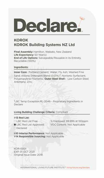
INTRODUCTION
TRANSPORT                                                         STRIPPABLE FILM
Generally the lengths of KOROK® are delivered to site by          KOROK® panels may be coated with a plastic film to provide
long trailers and articulated trucks. Therefore access to and     protection during handling and transportation. This film has a
on building sites must be adequate to accommodate these           very short life when exposed to exterior conditions and must
types of vehicles.                                                be removed immediately after installation.
Off loading and site storage or cranage onto site is the          It must not be left lying in the sun or at the site for more than
responsibility of the client and suitable arrangements must       a few hours. Failure to remove the film will lead to difficulties
be made prior to delivery.                                        later with its removal.
KOROK® products are packed and protected against
damage during delivery but care must be exercised during          CUTTING OF KOROK® PANELS
unloading.                                                        Its recommended that KOROK® panels are cut using a Hilti
Lengths must be adequately supported during unloading             DCH300 Electric Concrete Cutter with dust removal system.
and where packs are broken and panels lifted by hand, care        Hot swarf must not be allowed to contact pre-painted or
must be taken not to slide or drag the panel and scrape the       galvanized sheet material. Any grinding, welding or drillings
finished surfaces of the product.                                 carried out above the wall level must be done with the
                                                                  panels appropriately covered to avoid swarf contact.
HANDLING AND STORAGE                                              Failure to do so will result in unsightly staining of the surface
KOROK® panels must be stored under clean, dry and                 as the metal particles rust or oxidise.
ventilated conditions.
Where it is necessary for KOROK® Panels to be stored on-
                                                                  INSTALLATION
site they must be placed away from the building operations,       Specific design advice must be sought where KOROK® is to
if possible, in the order in which they will be fixed.            be subject to point loads or other distributed loading other
                                                                  than wind.
Storage must provide a firm and dry base, protected from
the weather, accidental damage and moisture.                      Ensure connections between KOROK® panels are
                                                                  properly made.
The panels must be stored on bearers no more than
2000mm apart. Stack heights are limited to 8 pallets.             Ensure connections of KOROK® panels to the structure
                                                                  are adequate.
Adequate cover must be provided and water must not lie on
or between the panel surfaces, which will cause staining and
degradation of the surface coatings.                              DEFINITIONS
                                                                  STC
If pallets become wet the KOROK® panels must without
                                                                  Sound Transmission Class is derived from an ASTM
delay be separated, wiped with a clean cloth and stacked so
                                                                  standard test procedure which rates the airborne sound
that the circulation of air will complete the drying process.
                                                                  transmission loss through building elements such as walls
                                                                  and ceilings. dB loss is measured at a 1/3 octave range
ON SITE HANDLING AND STORAGE                                      between 125Hz and 4000Hz. The minimum requirement for
Handle KOROK® panels carefully prior to installation.             residential Intertenancy is STC 55.
Avoid knocks, bumps and scratches, which may lead to
                                                                  FRR
maintenance issues later.
                                                                  Fire Resistance Rating is derived from a laboratory furnace
Store KOROK® panels on site flat or in their pallets and          test which gives a value in minutes for Structural adequacy,
ensure that KOROK® panels are dry prior to installation.          Integrity, and Insulation. Depending on design, all three may
                                                                  not be relevant to the building element.
CLEANING
At the completion of the job and at the finish of each day’s
work, it is essential that the completed area be thoroughly
cleaned of all swarf, rivet stems, nails, drillings and screws,
etc. normally associated with the installation of metal panels.

KOROK® INTERTENANCY TERRACED HOUSING SYSTEMS www.korok.com 0800 773 777                                                   .3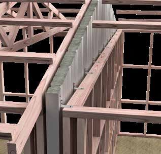
KOROK® TERRACED HOUSING INTERTENANCY
SYSTEMS

 Plasterboard

 Insulation as
 required for
 acoustic rating

 KOROK® panel

 Steel stud option available.

STRUCTURAL
MAXIMUM PERMISSIBLE HEIGHT                                      SUPPORT BRACKET SEPARATION
The total height of the central KOROK® panel in the KOROK®      KOROK® aluminium brackets are fixed into the panel and
Intertenancy Wall must not exceed 14.0 metres. For walls        spaced at no more than 3000 mm vertically and 500 mm
constructed above 12.0 metres in height contact KOROK®          horizontally. KOROK® aluminium brackets are required within
for KOROK® aluminium bracket maximum vertical bracket           1500mm of mid-wall joints.
spacing.

MID-WALL HORIZONTAL JOINTS
Mid-wall joints are incorporated into the KOROK® wall to
satisfy installation sequences. These mid-wall joints may be
staggered. Introducing back-to-back C-tracks stiffens the
wall. All other maximum details (wall maximum height and
bracket locations) are to be maintained.

.4                                          KOROK® INTERTENANCY TERRACED HOUSING SYSTEMS www.korok.com 0800 773 777
KOROK® TERRACED HOUSING INTERTENANCY
SYSTEMS

FRAMING                                                   DESIGN
Frames must be designed to meet the requirements of
NZBC Part B and consider the loading imposed on them by
                                                          CONSIDERATIONS
the KOROK® wall.
                                                          FIRE
                                                          KOROK® Intertenancy Systems provide a range of Fire
                                                          Resistance Ratings (FRR) (as outlined in the Systems
TIMBER FRAMING                                            Summary Tables). In the case of a fire, the wall frame on the
                                                          non-fire side of the KOROK® Intertenancy wall maintains
                                                          structural adequacy and provides lateral stability.
                                                          As the primary fire barrier, the KOROK® panels are located
                                                          in the cavity between the frames. The system permits
                                                          easy inclusion of services such as water and waste pipes,
                                                          electrical and communications cables, as long as the
                                                          KOROK® panels are not penetrated. Fire rated service
                                                          penetrations are allowed through KOROK® panels in the roof
                                                          space.
                                                          The FRR of the KOROK® intertenancy system relies on the
                                                          KOROK® panel wall and not on the performance of the
                                                          plasterboard linings or the cavity. Although penetrations
                                                          through the plasterboard linings do not affect the FRR of
                                                          the KOROK® Intertenancy system, penetrations may affect
                                                          acoustic performance (see ACOUSTIC PERFORMANCE
                                                          below).
                                                          To maintain the FRR of the KOROK® Intertenancy System
                                                          use only the specified KOROK® aluminium brackets to attach
                                                          the KOROK® panels to framing members. The KOROK®
                                                          aluminium bracket is designed to melt in the event of a fire,
STEEL FRAMING                                             which allows the framing members on the fire side to fall
                                                          away, protecting the adjoining dwellings.

                                                          ACOUSTIC PERFORMANCE
                                                          The KOROK® Intertenancy System has been independently
                                                          tested to ensure compliance with the NZBC requirements for
                                                          multi-unit residential construction.
                                                          Service pipes must not be in contact with the KOROK®
                                                          panels. Small penetrations through the plasterboard linings
                                                          are permitted, these may be placed back-to-back and
                                                          include:
                                                          • Normal residential electrical switches and power points
                                                          • Data, communications or electrical cables
                                                          • Copper, galvanised steel, or plastic water or waste water
                                                            pipes of up to 50mm nominal diameter
                                                          • Baths and shower bases
                                                          • Wall mounted cabinets or vanities

                                                          PLASTERBOARD FIXING INSTRUCTIONS
                                                          All plasterboard linings must be fixed in accordance with the
                                                          manufacturers fixing instructions.

KOROK® INTERTENANCY TERRACED HOUSING SYSTEMS www.korok.com 0800 773 777                                         .5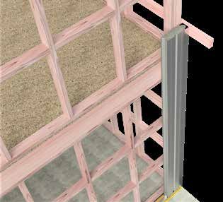
KOROK® TERRACED HOUSING INTERTENANCY
SYSTEMS
Multi-unit construction projects, such as town houses, and • Compliance with Building Code of Australia (BCA)
high density apartments, call for well-tested technology requirements for ‘discontinuous construction’
that’s simple to install. KOROK® Intertenancy systems offer supported in BCA Illustrated.
the benefits of proven fire and acoustic performance, and • The acoustic performance of the KOROK® Intertenancy
the security of a solid wall design. system exceeds the minimum requirements of the
The KOROK® Intertenancy system utilises KOROK®’s NZBC to provide superior combined fire, acoustic and
revolutionary clip-together technology. This makes it security wall systems.
simple for construction teams to erect walls within tight • Cost-effective configuration to achieve up to
time frames. Furthermore, the installation of KOROK® 120/120/120 Fire Resistance Rating (FRR).
Intertenancy system isn’t weather dependent. • Services penetrations through KOROK® panels are
KOROK®’s continuing investment in systems, to meet ever allowed in the roof space.
changing building trends, means the KOROK® Intertenancy
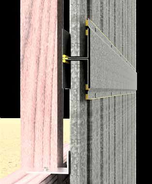
WHAT IS KOROK® INTERTENANCY
systems have been developed to keep pace with market
WALL?
requirements. KOROK® Intertenancy systems provide:
The KOROK® Intertenancy systems incorporate a KOROK®
• Compliance with New Zealand Building Code (NZBC) panel between double stud walls with insulation in both
Clause G6 ‘Protection from Noise’. framing cavities and plasterboard internal linings.
• Framing is designed to satisfy the requirements of Part
The fire-resistant KOROK® panels are held in position by
B of the NZBC. The KOROK® Intertenancy systems
KOROK® aluminium brackets fixed to the wall framing.
have been designed to provide FRR (as tested) and
meet the requirements of C/ASx, section 4.3 (structural KOROK® Intertenancy walls have been designed for
stability during fire) and complies with Part C of the installation by builders following accepted construction
NZBC. methodologies.
Typical intertenancy terraced housing wall
KOROK® C-track
KOROK® panel
Insulation to meet
acoustic requirements
Plasterboard
Plasterboard
KOROK® C-track
Framing to meet
relevant NZBC
requirements
.6 KOROK® INTERTENANCY TERRACED HOUSING SYSTEMS www.korok.com 0800 773 777KOROK® TERRACED
HOUSING
INTERTENANCY
SYSTEMS
KOROK® Intertenancy wall systems achieve up to
120/120/120 Fire Resistance Rating (FRR) and achieve a
minimum acoustic control rating of STC 63.
This manual covers both timber framed and steel framed
KOROK® Intertenancy wall systems.
BENEFITS
• Adding a steel panel forms a secure intertenancy wall. BEFORE FIRE - KOROK® aluminium brackets are
fixed to framing both sides of KOROK® fire barrier.
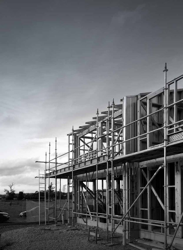
• No need for scaffolding.
• The clip together simplicity makes for rapid
construction.
• KOROK® Intertenancy wall is not adversely affected by
weather.
• Internal wall linings are installed, once the building is
closed in.
• Service penetrations, such as pipes, power points,
light fittings and switches are easily included within the
partition.
• Is lightweight so no additional foundations are required.
HOW THE SYSTEM WORKS
Conventional-framed wall systems rely on the internal
linings for fire-resistance. The KOROK® Intertenancy wall
DURING FIRE - KOROK® aluminium brackets on the
systems locate the main fire barrier between frames and is
fire side melt.
designed to protect the structure on the side opposite the
fire.
KOROK® aluminium brackets attach the KOROK®
Intertenancy wall panels to both frames. The aluminium
brackets on the fire side melt, allowing the structure on
the fire side to detach without causing damage leaving
the KOROK® fire barrier supported by aluminium brackets
connected to framing on the non-fire side.
AFTER FIRE - The adjoining occupancy is protected
by KOROK® Intertenancy wall.
KOROK® INTERTENANCY TERRACED HOUSING SYSTEMS www.korok.com 0800 773 777 .7KOROK® TERRACED HOUSING INTERTENANCY
SYSTEMS
WEST AUCKLAND FIRE
A massive blaze ripped through the unoccupied three-
storey building at 3:55am. Sixteen fire crews helped
extinguish the huge fire. A local resident said, “It was scary, it
was quite close. It was just going straight up.” She also said
while the event was horrible, it was “good to know” the fire
walls worked in the midst of high-density housing.
Photograph credit: Angela Nash
For terraced housing, the KOROK® panels are held in
position with KOROK® aluminium brackets within the timber
frame cavity. In the unfortunate event of a fire, the brackets
are designed to melt on the fire side and to remain intact on
the non-fire side, which in turn supports the KOROK® panel
fire barrier.
.8 KOROK® INTERTENANCY TERRACED HOUSING SYSTEMS www.korok.com 0800 773 777KOROK® TERRACED HOUSING INTERTENANCY
SYSTEMS
TABLE 1 - SYSTEMS SUMMARY TABLE
These systems are described in detail in the following pages.
SPEC. STC FRR WALL FRAME CAVITY SYSTEM SUMMARY PAGE
CODE THICKNESS*
KIT01 64 60/60/60 288mm 90mm Minimum 86mm KOROK® 51mm panels (600 Kg/m3 density) + 11
timber overall between the 1 layer 10mm GIB® Standard plasterboard or
frame framing. equivalent each side
each
side Framing not to Acoustic insulation must be either Autex
touch KOROK® GreenStuf SW90 or Pink Batts R 2.2 each side
panel or fire flashing
KOROK® metal fire flashing is installed to the top
C-track. KOROK® metal KIT flashing is installed to
horizontal joints.
KIT01A 64 60/60/30 288mm 90mm Minimum 86mm KOROK® 51mm panels (600 Kg/m3 density) + 12
timber overall between the 1 layer 10mm GIB® Standard plasterboard or
frame framing. equivalent each side
each
side Framing not to Acoustic insulation must be either Autex
touch KOROK® GreenStuf SW90 or Pink Batts R 2.2 each side
panel
KIT04 69 60/60/60 294mm 90mm Minimum 86mm KOROK® 51mm panels (600 Kg/m3 density) + 1 13
timber overall between the layer 13mm GIB Noiseline® or equivalent each
frame framing. side.
each
side Framing not to Acoustic insulation must be either Autex
touch KOROK® GreenStuf SW90 or Pink Batts R 2.2 each side
panel or fire flashing
KOROK® metal fire flashing is installed to the top
C-track. KOROK® metal KIT flashing is installed to
horizontal joints.
KIT06 63 120/120/120 315mm 90mm Minimum 113mm KOROK® 78mm panels (400 Kg/m3 density) + 14
timber overall between the 1 layer 10mm GIB® Standard plasterboard or
frame framing. equivalent each side
each
side Framing not to Acoustic insulation must be either Autex
touch KOROK® GreenStuf SW90 or Pink Batts R 2.2 each side
panel or fire flashing
KOROK® metal fire flashing is installed to the top
C-track. KOROK® metal KIT flashing is installed to
horizontal joints.
KIT06A 63 120/120/60 315mm 90mm Minimum 113mm KOROK® 78mm panels (400 Kg/m3 density) + 15
timber overall between the 1 layer 10mm GIB® Standard plasterboard or
frame framing. equivalent each side
each
side Framing not to Acoustic insulation must be either Autex
touch KOROK® GreenStuf SW90 or Pink Batts R 2.2 each side
panel
KIT09 69 120/120/60 321mm 90mm Minimum 113mm KOROK® 78mm panels (400 Kg/m3 density) + 16
timber overall between the 1 layer 13mm GIB Noiseline® or equivalent one
frame framing. side + 1 layer 13mm GIB Aqualine® or equivalent
each (wet) or 13mm GIB Noiseline® or equivalent (dry)
side Framing not to other side
touch KOROK®
panel Acoustic insulation must be either Autex
GreenStuf SW90 or Pink Batts R 2.2 each side
*Nominal thickness
FRR (FIRE RESISTANCE RATING)
FRR ratings are based on the KOROK® panel wall. The cavity and linings contribute to the STC rating but are not relevant to
the stated FRR.
KOROK® INTERTENANCY TERRACED HOUSING SYSTEMS www.korok.com 0800 773 777 .9KOROK® TERRACED HOUSING INTERTENANCY
SYSTEMS
TABLE 1 - SYSTEM SUMMARY TABLES (CONT.)
For further information on the following systems, please contact us at KOROK® on 0800 773 777 or info@korok.com.
SPEC. STC FRR WALL FRAME CAVITY SYSTEM SUMMARY
CODE THICKNESS*
KIT02 66 60/60/60 288mm 90mm Minimum 86mm KOROK® 51mm panels (600 Kg/m3 density) + 1 layer 10mm
timber overall between GIB® Standard plasterboard or equivalent one side + 1 layer
frame the framing. 10mm GIB Noiseline® or equivalent the other
each Framing not to
side touch KOROK® Acoustic insulation must be either Autex GreenStuf SW90 or
panel or fire Pink Batts R 2.2 each side
flashing KOROK® metal fire flashing is installed to the top C-track.
KOROK® metal KIT flashing is installed to horizontal joints.
KIT03 67 60/60/60 288mm 90mm Minimum 86mm KOROK® 51mm panels (600 Kg/m3 density) + 1 layer 10mm
timber overall between GIB Noiseline® or equivalent each side
frame the framing.
each Framing not to Acoustic insulation must be either Autex GreenStuf SW90 or
side touch KOROK® Pink Batts R 2.2 each side
panel or fire KOROK® metal fire flashing is installed to the top C-track.
flashing KOROK® metal KIT flashing is installed to horizontal joints.
KIT05 66 60/60/60 294mm 90mm Minimum 86mm KOROK® 51mm panels (600 Kg/m3 density) + 1 layer 13mm
timber overall between GIB® Standard plasterboard or equivalent each side
frame the framing.
each Framing not to Acoustic insulation must be either Autex GreenStuf SW90 or
side touch KOROK® Pink Batts R 2.2 each side
panel or fire KOROK® metal fire flashing is installed to the top C-track.
flashing KOROK® metal KIT flashing is installed to horizontal joints.
KIT07 66 120/120/120 315mm 90mm Minimum KOROK® 78mm panels (400 Kg/m3 density) + 1 layer 10mm
timber 113mm overall GIB® Standard plasterboard or equivalent one side + 1 x
frame between the 10mm GIB Noiseline® or equivalent other side
each framing. Framing
side not to touch Acoustic insulation must be either Autex GreenStuf SW90 or
KOROK® panel Pink Batts R 2.2 each side
or fire flashing KOROK® metal fire flashing is installed to the top C-track.
KOROK® metal KIT flashing is installed to horizontal joints.
KIT08 67 120/120/120 315mm 90mm Minimum KOROK® 78mm panels (400 Kg/m3 density) + 1 layer 10mm
timber 113mm overall GIB Noiseline® or equivalent one side + 1 layer 10mm GIB
frame between the Aqualine® or equivalent (wet) or 10mm GIB Noiseline® or
each framing. Framing equivalent (dry) other side
side not to touch
KOROK® panel Acoustic insulation must be either Autex GreenStuf SW90 or
or fire flashing Pink Batts R 2.2 each side
KOROK® metal fire flashing is installed to the top C-track.
KOROK® metal KIT flashing is installed to horizontal joints.
KIT10 67 120/120/120 321mm 90mm Minimum KOROK® 78mm panels (400Kg/m3 density) + 1 layer 13mm
timber 113mm overall GIB® Standard plasterboard or equivalent each side
frame between the
each framing. Framing Acoustic insulation must be either Autex GreenStuf SW90 or
side not to touch Pink Batts R 2.2 each side
KOROK® panel KOROK® metal fire flashing is installed to the top C-track.
or fire flashing KOROK® metal KIT flashing is installed to horizontal joints.
*Nominal thickness
FRR (FIRE RESISTANCE RATING)
FRR ratings are based on the KOROK® panel wall. The cavity and linings contribute to the STC rating but are not relevant to
the stated FRR.
.10 KOROK® INTERTENANCY TERRACED HOUSING SYSTEMS www.korok.com 0800 773 777KIT01 - 60/60/60
SPEC. STC FRR WALL FRAME CAVITY SYSTEM SUMMARY
CODE THICKNESS*
KIT01 64 60/60/60 288mm 90mm Minimum 86mm KOROK® 51mm panels (600 Kg/m3 density) + 1 layer 10mm
timber overall between GIB® Standard plasterboard or equivalent each side
frame each the framing
side Acoustic insulation must be either Autex GreenStuf SW90 or
Framing not to Pink Batts R 2.2 each side
touch KOROK®
panel or fire KOROK® metal fire flashing is installed to the top C-track.
flashing KOROK® metal KIT flashing is installed to horizontal joints.
*Nominal thickness
KOROK® PANEL SUPPORT BRACKETS
KOROK® 51mm panels are located in KOROK® C-track KOROK® aluminium brackets (PN AB10) are fixed into the
60mm high x 51mm wide x 1.15B.M.T. KOROK® panels must panel and spaced at a maximum of 3.0 metres vertically and
not exceed 12 metres in height. 500 mm horizontally.
FRAMING LINING
Frames must be designed to meet the requirements of Frames are lined with 1 layer of 10mm GIB® Standard
NZBC Part B and consider the loading imposed on them by plasterboard or equivalent each side of the wall. Joints must
the KOROK® wall. occur over framing.
Cavity must be 86mm overall. Framing not to touch KOROK® Plasterboard linings are installed to the manufacturer’s
panel or fire flashing. specification.
ACOUSTIC INSULATION SEALANT
Acoustic insulation must be either Autex GreenStuf SW90 Beads of fire rated sealant are required around the perimeter
or Pink Batts R 2.2 or equivalent. of the KOROK® system. Refer to the installation section of
this publication for more information on sealant application,
and to the KOROK® Components Summary for approved
sealants.
KIT01 Steel stud option available.
60 x 51mm KOROK®
Fire flashing
C-track
1 layer 10mm GIB®
Standard plasterboard Acoustic insulation
or equivalent
51mm KOROK®
1 layer 10mm GIB®
density 600kg/m3
Standard plasterboard
or equivalent
Acoustic insulation
STC
90 x 45mm framing
64
KOROK® INTERTENANCY TERRACED HOUSING SYSTEMS www.korok.com 0800 773 777 .11KIT01A - 60/60/30
SPEC. STC FRR WALL FRAME CAVITY SYSTEM SUMMARY
CODE THICKNESS*
KIT01A 64 60/60/30 288mm 90mm Minimum 86mm overall KOROK® 51mm panels (600 Kg/m3 density) + 1 layer
timber between the framing 10mm GIB® Standard plasterboard or equivalent each
frame side
each Framing not to touch
side KOROK® panel Acoustic insulation must be either Autex GreenStuf
SW90 or Pink Batts R 2.2 each side
*Nominal thickness
KOROK® PANEL SUPPORT BRACKETS
KOROK® 51mm panels are located in KOROK® C-track KOROK® aluminium brackets (PN AB10) are fixed into the
60mm high x 51mm wide x 1.15B.M.T. KOROK® panels must panel and spaced at a maximum of 3.0 metres vertically and
not exceed 12 metres in height. 500 mm horizontally.
FRAMING LINING
Frames must be designed to meet the requirements of Frames are lined with 1 layer of 10mm GIB® Standard
NZBC Part B and consider the loading imposed on them by plasterboard or equivalent each side of the wall. Joints must
the KOROK® wall. occur over framing.
Cavity must be 86mm overall. Framing not to touch KOROK® Plasterboard linings are installed to the manufacturer’s
panel. specification.
ACOUSTIC INSULATION SEALANT
Acoustic insulation must be either Autex GreenStuf SW90 Beads of fire rated sealant are required around the perimeter
or Pink Batts R 2.2 or equivalent. of the KOROK® system. Refer to the installation section of
this publication for more information on sealant application,
and to the KOROK® Components Summary for approved
sealants.
KIT01A Steel stud option available.
60 x 51mm KOROK®
C-track
1 layer 10mm GIB®
Standard plasterboard
Acoustic insulation
or equivalent
51mm KOROK®
density 600kg/m3 1 layer 10mm GIB®
Standard
plasterboard or
Acoustic insulation equivalent
90 x 45mm framing
STC
64
.12 KOROK® INTERTENANCY TERRACED HOUSING SYSTEMS www.korok.com 0800 773 777KIT04 - 60/60/60
SPEC. STC FRR WALL FRAME CAVITY SYSTEM SUMMARY
CODE THICKNESS*
KIT04 69 60/60/60 294mm 90mm Minimum 86mm KOROK® 51mm panels (600 Kg/m3 density) + 1 layer 13mm
timber overall between the GIB Noiseline® or equivalent each side
frame framing
each Acoustic insulation must be either Autex GreenStuf SW90 or
side Framing not to Pink Batts R 2.2 each side
touch KOROK®
panel or fire flashing KOROK® metal fire flashing is installed to the top C-track.
KOROK® metal KIT flashing is installed to horizontal joints.
*Nominal thickness
KOROK® PANEL SUPPORT BRACKETS
KOROK® 51mm panels are located in KOROK® C-track KOROK® aluminium brackets (PN AB10) are fixed into the
60mm high x 51mm wide x 1.15B.M.T. KOROK® panels must panel and spaced at a maximum of 3.0 metres vertically and
not exceed 12 metres in height. 500 mm horizontally.
FRAMING LINING
Frames must be designed to meet the requirements of Frames are lined with 1 layer of 13mm GIB Noiseline® or
NZBC Part B and consider the loading imposed on them by equivalent each side of the wall. Joints must occur over
the KOROK® wall. framing.
Cavity must be 86mm overall. Framing not to touch KOROK® Plasterboard linings are installed to the manufacturer’s
panel or fire flashing. specification.
ACOUSTIC INSULATION SEALANT
Acoustic insulation must be either Autex GreenStuf SW90 Beads of fire rated sealant are required around the perimeter
or Pink Batts R 2.2 or equivalent. of the KOROK® system. Refer to the installation section of
this publication for more information on sealant application,
and to the KOROK® Components Summary for approved
sealants.
KIT04 Steel stud option available.
60 x 51mm KOROK® Fire flashing
C-track
1 layer 13mm GIB
Noiseline® or equivalent Acoustic insulation
51mm KOROK®
density 600kg/m3 1 layer 13mm GIB
Noiseline® or equivalent
Acoustic insulation
90 x 45mm framing
STC
69
KOROK® INTERTENANCY TERRACED HOUSING SYSTEMS www.korok.com 0800 773 777 .13KIT06 - 120/120/120
SPEC. STC FRR WALL FRAME CAVITY SYSTEM SUMMARY
CODE THICKNESS*
KIT06 63 120/120/120 315mm 90mm Minimum KOROK® 78mm panels (400 Kg/m3 density) + 1 layer 10mm
timber 113mm overall GIB® Standard plasterboard or equivalent each side
frame between the
each framing. Framing Acoustic insulation must be either Autex GreenStuf SW90 or
side not to touch Pink Batts R 2.2 each side
KOROK® panel KOROK® metal fire flashing is installed to the top C-track.
or fire flashing KOROK® metal KIT flashing is installed to horizontal joints.
*Nominal thickness
KOROK® PANEL SUPPORT BRACKETS
KOROK® 78mm panels are located in KOROK® C-track KOROK® aluminium brackets (PN AB10) are fixed into the
60mm high x 80mm wide x 1.15B.M.T. KOROK® panels must panel and spaced at a maximum of 3.0 metres vertically and
not exceed 14 metres in height. 500 mm horizontally.
FRAMING LINING
Frames must be designed to meet the requirements of the Frames are lined with 1 layer of 10mm GIB® Standard
NZBC Part B, taking into consideration the load imposed on plasterboard or equivalent each side of the wall. Joints must
them by the KOROK® wall. occur over framing.
Cavity must be 113mm overall. Framing not to touch Plasterboard linings are installed to the manufacturer’s
KOROK® panel or fire flashing. specification.
ACOUSTIC INSULATION SEALANT
Acoustic insulation must be either Autex GreenStuf SW90 Beads of fire rated sealant are required around the perimeter
or Pink Batts R 2.2 or equivalent. of the KOROK® system. Refer to the installation section of
this publication for more information on sealant application,
and to the KOROK® Components Summary for approved
sealants.
KIT06 Steel stud option available.
60 x 80mm KOROK® Fire flashing
C-track
1 layer 10mm Acoustic insulation
GIB® Standard
plasterboard or
equivalent
1 layer 10mm
GIB® Standard
90 x 45mm framing plasterboard or
equivalent
78mm KOROK®
density 400kg/m3
STC
90 x 45mm framing
63
.14 KOROK® INTERTENANCY TERRACED HOUSING SYSTEMS www.korok.com 0800 773 777KIT06A - 120/120/60
SPEC. STC FRR WALL FRAME CAVITY SYSTEM SUMMARY
CODE THICKNESS*
KIT06A 63 120/120/60 315mm 90mm Minimum 113mm KOROK® 78mm panels (400 Kg/m3 density) + 1 layer 10mm
timber overall between the GIB® Standard plasterboard or equivalent each side
frame framing. Framing
each not to touch Acoustic insulation must be either Autex GreenStuf SW90
side KOROK® panel or Pink Batts R 2.2 each side
*Nominal thickness
KOROK® PANEL SUPPORT BRACKETS
KOROK® 78mm panels are located in KOROK® C-track KOROK® aluminium brackets (PN AB10) are fixed into the
60mm high x 80mm wide x 1.15B.M.T. KOROK® panels must panel and spaced at a maximum of 3.0 metres vertically and
not exceed 14 metres in height. 500 mm horizontally.
FRAMING LINING
Frames must be designed to meet the requirements of Frames are lined with 1 layer of 10mm GIB® Standard
NZBC Part B and consider the loading imposed on them by plasterboard or equivalent each side of the wall. Joints must
the KOROK® wall. occur over framing.
Cavity must be 113mm overall. Framing not to touch Plasterboard linings are installed to the manufacturer’s
KOROK® panel. specification.
ACOUSTIC INSULATION SEALANT
Acoustic insulation must be either Autex GreenStuf SW90 Beads of fire rated sealant are required around the perimeter
or Pink Batts R 2.2 or equivalent. of the KOROK® system. Refer to the installation section of
this publication for more information on sealant application,
and to the KOROK® Components Summary for approved
sealants.
KIT06A Steel stud option available.
60 x 80mm KOROK®
C-track
1 layer 10mm GIB®
Acoustic insulation
Standard plasterboard
or equivalent
90 x 45mm framing
1 layer 10mm GIB®
Standard plasterboard
or equivalent
78mm KOROK®
density 400kg/m3
STC
90 x 45mm framing
63
KOROK® INTERTENANCY TERRACED HOUSING SYSTEMS www.korok.com 0800 773 777 .15KIT09 - 120/120/60
SPEC. STC FRR WALL FRAME CAVITY SYSTEM SUMMARY
CODE THICKNESS*
KIT09 69 120/120/60 321mm 90mm Minimum KOROK® 78mm panels (400 Kg/m3 density) + 1 layer 13mm GIB
timber 113mm overall Noiseline® or equivalent one side + 1 layer 13mm GIB Aqualine®
frame between or equivalent(wet) or 13mm GIB Noiseline® or equivalent ((dry)
each the framing. other side
side Framing not to
touch KOROK® Acoustic insulation must be either Autex GreenStuf SW90 or
panel Pink Batts R 2.2 each side
*Nominal thickness
KOROK® PANEL ACOUSTIC INSULATION
KOROK® 78mm panels are located in KOROK® C-track Acoustic insulation must be either Autex GreenStuf SW90
60mm high x 80mm wide x 1.15B.M.T. KOROK® panels must or Pink Batts R 2.2 or equivalent.
not exceed 14 metres in height.
LINING
FRAMING Frames are lined with 1 layer of 13mm GIB Noiseline® or
Frames must be designed to meet the requirements of equivalent on one side and one layer of 13mm GIB Aqualine®
NZBC Part B and consider the loading imposed on them by or equivalent (wet) or 13mm GIB Noiseline® or equivalent
the KOROK® wall. (dry) each side of the wall. Joints must occur over framing.
Cavity must be 113mm overall. Framing not to touch Plasterboard linings are installed to the manufacturer’s
KOROK® panel. specification.
SUPPORT BRACKETS SEALANT
KOROK® aluminium brackets (PN AB10) are fixed into the Beads of fire rated sealant are required around the perimeter
panel and spaced at a maximum of 3.0 metres vertically and of the KOROK® system. Refer to the installation section of
500 mm horizontally. this publication for more information on sealant application,
and to the KOROK® Components Summary for approved
sealants.
KIT09 Steel stud option available.
60 x 80mm KOROK®
C-track
1 layer 13mm GIB
Noiseline® or equivalent Acoustic insulation
90 x 45mm framing
1 layer 13mm
GIB Aqualine® or
78mm KOROK® equivalent or 13mm
density 400kg/m3 GIB Noiseline® or
equivalent
STC
69
.16 KOROK® INTERTENANCY TERRACED HOUSING SYSTEMS www.korok.com 0800 773 777TERRACED HOUSING INTERTENANCY
SYSTEMS INSTALLATION
Installation of the KOROK® Intertenancy Systems requires When the framing on the other side is completed the
the attachment of the KOROK® panels to framing members KOROK® aluminium brackets are installed on that side.
using KOROK® aluminium brackets. The framing is set out The sequence of construction must be planned to
to allow for the required clearances on both sides of the accommodate the progressive erection of the KOROK®
KOROK® Intertenancy wall. panels.
After the framing on one side of the KOROK® Intertenancy The KOROK® panels can also be installed after both the wall
wall is completed, the KOROK® Intertenancy wall is installed frames have already been erected. However, this will not be
and attached with KOROK® aluminium brackets. as efficient.
1 Place a bead of fire rated sealant between the floor
and C-track on the centre line of the KOROK® wall position.
Refer the KOROK® Components Summary for approved
sealants.
Where the timber framing sits on HIANDRI packers use
KOROK® J-track, in place of C-track, with the 70mm leg to
the wall framing side.
2 Fix the C-track at maximum centres of 400mm
with 6.5mm x 32mm Hilti DBZ Fastenings.
Place fire rated sealant in the internal corner of the C-track.
When setting out the C-track ensure there is enough
clearance from the wall frame giving consideration to any
KOROK® KIT flashings.
If the surrounding surface is uneven or if you are not sure
you have a good seal, add another bead of fire rated sealant
along the C-track floor junction.
3 Fix the side C-track to the first panel using
10x16mm Wafer Tek screws at 400mm centres both sides,
prior to installing.
Then place the first panel into the floor C-track.
C-track
KOROK® INTERTENANCY TERRACED HOUSING SYSTEMS www.korok.com 0800 773 777 .17TERRACED HOUSING INTERTENANCY SYSTEMS INSTALLATION 4 You may temporarily brace the C−track. 5 After every second panel is installed, fix the KOROK® aluminium brackets into the panel using 2 each Hex Head Type 17 14g x 35mm screws and 1 each Hex Head Type 17 14g x 35mm screws into framing at no more than 3.0 metres above floor level. 6 Continue placing panels into position, ensuring the tongue and groove are fully locked. Cut the last panel to fit the wall length and place C-track on the cut panel and screw off with 10 x 16 Wafer Tek screws at 400mm centres both sides. Screw off the bottom C-track with 10 x 16 Wafer Tek screws at 250mm centres both sides. .18 KOROK® INTERTENANCY TERRACED HOUSING SYSTEMS www.korok.com 0800 773 777
TERRACED HOUSING INTERTENANCY
SYSTEMS INSTALLATION

7         Place a bead of fire rated sealant into the internal
corner of the C-track. Fit the C-track to the top of the panels
hard down and screw to panels with 10x16mm Wafer Tek
screws at 250mm centres both sides.
Fix the remaining rows of KOROK® aluminium brackets to the
timber frame and panels at a maximum 500mm horizontal
centres and 3.0 metres vertically into the panel.
There must be a row of KOROK® aluminium brackets within
1500mm of any mid-wall horizontal joint.

8         Place bead of fire rated sealant on top of C-track.
Place the second C-track directly on top and fix with Hex
Head SDS 14g x 22mm screws at 400mm centres.

9        Place bead of fire sealant into the internal corner of
the top C-track.

KOROK® INTERTENANCY TERRACED HOUSING SYSTEMS www.korok.com 0800 773 777   .19
TERRACED HOUSING INTERTENANCY
SYSTEMS INSTALLATION

10         Fix the vertical C-track to the first panel using
10x16mm Wafer Tek screws at 400mm centres both sides,
prior to installing.
Place the first panel in position and fix with a KOROK®
aluminium bracket no more than 3.0 metres vertically from
the previous row of brackets.
You may use a temporary brace.

11        Continue placing the KOROK® panels.
Fix panels to timber framing with KOROK® aluminium
brackets at 500mm horizontal centres into the panel and
no more than 3.0 metres from the last row of KOROK®
aluminium brackets.
Fix the vertical C-track to the last KOROK® panel using
10x16mm Wafer Tek screws at 400mm centres both sides.
Screw off the bottom C-track with 10 x 16 Wafer Tek screws
at 250mm centres both sides.
Cutting of the KOROK® panels to the rake and height may be
carried out when all the panels are erected.

12        Place a bead of fire sealant into the internal corner
of the top C-track.
Place the top C-track hard down on top of KOROK® panels
and fix off with 10x16mm Wafer Tek screws at 250mm
centres one side.
Fix the KOROK® aluminium brackets to timber framing and
panels at 500mm horizontal centres with Hex Head Type 17
14g x 35mm screws. Ensure wall is straight and true.
Place a bead of fire sealant around the join edge between
the C-track and the panel.

.20                                           KOROK® INTERTENANCY TERRACED HOUSING SYSTEMS www.korok.com 0800 773 777
TERRACED HOUSING INTERTENANCY
SYSTEMS INSTALLATION

13        HEAD TRACK PROTECTION
Check if the system you are installing requires head track protection. This applies to KIT 51mm 60/60/60 and KIT 78mm,
120/120/120 systems. There are three options:

13.1             Install a KOROK® Fire flashing at the top
C-track. The KOROK® Fire flashing is fixed to the panels at
250mm centres using Wafer Tek 10g - 16 x 16mm screws.
Place a bead of fire sealant around the perimeter of the
KOROK® Fire flashing and over any joins.

                            OR

13.2              Install a 13mm GIB Fyreline® or
equivalent x 120mm strip with sealant fixed at 250mm
centres top and bottom, using 6g x 32mm drywall screws.

                            OR

13.3                  Install adequate mineral or ceramic wool,
friction-fitted to prevent insulation failure, with a nominal
density of 60kg/m3.

KOROK® INTERTENANCY TERRACED HOUSING SYSTEMS www.korok.com 0800 773 777                                          .21
TERRACED HOUSING INTERTENANCY
SYSTEMS INSTALLATION
14 Install a KOROK® KIT flashing over the mid-
wall joint fixed at 250mm centres top and bottom using
10x16mm Wafer Tek screws.
Apply a bead of fire sealant along both flashing edges.
This applies to KIT 51mm 60/60/60 and KIT 78mm,
120/120/120 systems.
15 Ensure the wall is screwed off at each panel joint on one side at 1000mm centres vertically with 10x16 Wafer Tek
screws. The horizontal bottom and mid-wall C-track is screwed off to the KOROK® panel with 10x16 Wafer Tek screws at 250mm
centres both sides.
1000mm max.
.22 KOROK® INTERTENANCY TERRACED HOUSING SYSTEMS www.korok.com 0800 773 777TERRACED HOUSING INTERTENANCY SYSTEMS INSTALLATION 16 Ensure all C-track / panel junctions have been sealed with fire rated sealant. Ensure all KOROK® aluminium brackets are in place and fixed correctly. 17 Once the framing on the second side is completed, fix KOROK® aluminium brackets into the panels at 500mm horizontal centres and a maximum of 3.0 metres vertically. TABLE 2 - SCREW PLACEMENT WALL PANELS Panels are fixed together at every panel joint at the vertical centres. Panel Thickness Panel Max. Wall Panel to Panel Max. Sides KOROK Wall Notes: (mm) Orientation Height (m) Centres (mm) System or similar 51 Vertical 12 1000 One KIT01 to KIT05 10g - 16 x 16mm Wafer Tek 78 Vertical 14 1000 One KIT06 to KIT10 10g - 16 x 16mm Wafer Tek FINAL CHECK At the completion of the job and at the finish of each day’s work, it is essential that the completed area be thoroughly cleaned of all swarf, rivet stems, nails, drillings and screws etc. normally associated with the installation of metal KOROK® panels. Remove any remaining strippable film, check all fixings are correctly installed, all fire and acoustic sealant is applied correctly. KOROK® INTERTENANCY TERRACED HOUSING SYSTEMS www.korok.com 0800 773 777 .23
TERRACED HOUSING INTERTENANCY SYSTEMS
TYPICAL CONSTRUCTION DETAILS
ROOF INTERSECTION
   ROOF INTERSECTION

     Mineral wool or ceramic fibre
     insulation
                                                                          Roof purlins
     Fire Rated Sealant laid in with
     caulking gun as specified

     KOROK® C-track 1.15 BMT fixed
     to top of KOROK® panels
                                                                          Roof framing
     KOROK® top track fire flashing.
     Refer to system specification

     KOROK® panels

                                                                          Ceiling batten

                                                                          KOROK® aluminium brackets
                                                                          fixed 3000mm max. vertically and
                                                                          500mm max. horizontally
     Linings as specified

                                                                          FRR (Fire resistance rating)
                                                                          are based on the KOROK®
                                                                          panel wall. The cavity and
     Insulation as specified                                              linings contribute to the STC
                                                                          rating but are not relevant to
                                                                          the stated FRR

.24                                    KOROK® INTERTENANCY TERRACED HOUSING SYSTEMS www.korok.com 0800 773 777
TERRACED HOUSING INTERTENANCY SYSTEMS
TYPICAL CONSTRUCTION DETAILS
ROOF INTERSECTION
ROOF INTERSECTION
Mineral wool or ceramic fibre
insulation
Roof purlins
Fire Rated Sealant laid in with
caulking gun as specified
Solid blocking between purlins
KOROK® C-track 1.15 BMT fixed
to top of KOROK® panels
Roof framing
KOROK® top track fire flashing.
Refer to system specification
KOROK® panels
Ceiling batten
KOROK® aluminium brackets
fixed 3000mm max. vertically and
500mm max. horizontally
Linings as specified
FRR (Fire resistance rating)
are based on the KOROK®
panel wall. The cavity and
Insulation as specified linings contribute to the STC
rating but are not relevant to
the stated FRR
KOROK® INTERTENANCY TERRACED HOUSING SYSTEMS www.korok.com 0800 773 777 .25TERRACED HOUSING INTERTENANCY SYSTEMS
TYPICAL CONSTRUCTION DETAILS
ROOF INTERSECTION MINERAL WOOL TOP TRACK
Roof Intersection Mineral Wool Top Track 60/60/60 FRR
Mineral wool or ceramic fibre
insulation
Mineral wool or ceramic fibre
insulation Roof purlins
Fire Rated Sealant laid in with
caulking gun as specified
KOROK® C-track 1.15 BMT fixed
to top of KOROK® panels
Roof framing
KOROK® panels
Ceiling batten
KOROK® aluminium brackets
fixed 3000mm max. vertically and
500mm max. horizontally
Linings as specified
Linings as specified
Insulation as specified
.26 KOROK® INTERTENANCY TERRACED HOUSING SYSTEMS www.korok.com 0800 773 777You can also read