Horizontal Façade System Trimoterm FTV
←
→
Page content transcription
If your browser does not render page correctly, please read the page content below
Horizontal Façade System Trimoterm FTV

                      Technical document No. 17 / Version 5 / October 2011
CONTENT

1.0 Technical Description of the Horizontal Façade System [1]
       1.1 General [1]
       1.2 Panel Profile [1]
       1.3 Panel Composition [3]
       1.4 Technical Data [3]
		 1.4.1 Basic Technical Data [3]
		 1.4.2 Coatings [4]

2.0 Design Procedure [5]
      2.1 Panel Thickness Selection [5]
      2.2 Structural Design Data [5]
      2.3 Fixing Methods [5]
      2.4 Required Number of Screws for Fixing of a Façade to a Steel Structure According to DIN 1055 [5]
      2.5 Arrangement of Spike Anchors for Direct Fixing of a Façade to a Concrete Structure [5]
      2.6 Load Transfer to Neighbouring Panels near Openings [6]
      2.7 Design of Details in Accordance with Assembly Instructions [6]

3.0 Assembly Instructions [7]
       3.1 Installation Recommendations [7]
       3.2 Sealing [8]
       3.3 Lifting Methods [8]
       3.4 Installation Details [9]
		           3.4.1 Conection to the Main Beam [9]
		           3.4.2 Preformed Corner Element [10]
		           3.4.3 Installation of Windows in Horizontal Façades by Means of HF5 Aluminium Flat Profile [11]
       3.5 Fixing a Horizontal Façade to a Steel Structure [12]
		 3.5.1 Performance of a Load-bearing Steel Structure [12]
		 3.5.2 Fixing a Horizontal Façade to a Steel Structure by HF102 Aluminium Fixing Profile [13]
		 3.5.3 Temporary Fixing [13]
		 3.5.4 Application of Seals on Overlaying Spots of a Panel [14]
		 3.5.5 Assembly of Aluminium Profiles [14]
		           3.5.5.1 Assembly of HF102 Aluminium Fixing profile [14]
		           3.5.5.2 Assembly of HF4 Aluminium Fixing profile [15]
       3.6 Fixing of a Horizontal Façade to a Concrete Structure [16]
		 3.6.1 Method of Fixing a Horizontal Façade to a Concrete Structure [16]
		 3.6.2 Fixing by SPIKE DS Impact Anchors [16]
		 3.6.3 Fixing to an Uneven Structure [17]
		           3.6.3.1 Fixing a Horizontal Façade by a Levelling Profile [18]
		           3.6.3.2 Fixing of a Horizontal Façade by a Wide Levelling Profile [18]
  		 3.6.4 Welded Type of a Levelling Structure [19]

4.0 Packing, Transport and Storing [20]

5.0 Maintenance [20]
      5.1 Annual Checking of a Façade [20]
      5.2 General Recommendations [20]

All rights to alteration reserved. The last versions of documents is available on www.trimo.eu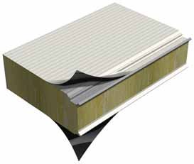
1.0 Technical Description of the Horizontal Façade System
1.1    General
       The basic horizontal façade system consists of Trimoterm FTV panels of modular widths 1000 and 1200 mm.

       The range of applications for the horizontal façade system is extremely wide. They are suitable for business,
       comercial, leisure, trade, industrial buildings and buildings constructed for representative purposes. The horizontal
       façade system has excellent technical properties, a long life span and allows the greatest creative freedom in façade
       design.

       The system of Trimoterm fireproof panels ensures high fire resistance, excellent thermal and sound insulation and
       hygienic perfection. The panels are used primarily as curtain walls, partition walls, fire walls and ceilings, but are
       also suitable for the use in food-processing and chemical industry.

1.2    Panel Profile
               Fig. 1a: Possible forms of Trimoterm FTV 1200 façade panels
                                                                                                       Side A

                                                                                                       Side B

               S - profile (standard profile)

               V - profile (v)
                                                                                          6.2

               V - profile (v2)
                                                                                                     6.2

               V - profile (v6)
                                                                                                     6.2

               Smooth profile (G, g)

               Micro-lined profile (m)

                                                                                     7.5 7.5

               Micro-lined profile (m2)

                                                                             1.0
                                                                                      10 10             20

               Micro-lined profile (m3)

                                                                             1.5
                                                                                          15    15         30

               Multi vario profile (X01)

                    Profile Type                  A   B
                    S - profile (s)               •   •
                    V - profile (v, v2, v6)       •   •
                    Smooth profile (G, g)         •   •
                    Micro-lined profile (m, m3)   •
                    Micro-lined profile (m2)          •     Side A is usually the external side of a panel.
                                                            Steel sheet thickness for profile v2, v6, G-gladio and Multi vario
                    Multi vario (X)               •         (except X01 profile) is 0.7 mm.

No.17/V-5/10-2011                                                                                                                1
Fig. 1b: Possible forms of Trimoterm FTV 1000 façade panels
Side A
Side B
S - profile (standard profile)
V - profile (v)
6.2
V - profile (v2)
6.2
Smooth profile (G, g)
Micro-lined profile (m)
7.5 7.5
Micro-lined profile (m2)
1.0
10 10 20
Micro-lined profile (m3)
1.5
15 15 30
Multi vario profile (X01)
Profile Type A B
S - profile (s) • •
V - profile (v, v2) • •
Smooth profile (g, G) • •
Micro-lined profile (m, m3) •
Micro-lined profile (m2) • Side A is usually the external side of a panel.
Steel sheet thickness for profile v2, G-gladio and Multi vario
Multi vario (X) • (except X01 profile) is 0.7 mm.
2 No.17/V-5/10-20111.3 Panels Composition
Trimoterm FTV fireproof panels consist of two shallow profiled, coated sheet faces in thickneses of 0.5 mm,
0.6 mm or 0.7 mm. The steel sheet is bonded to the panel core made of non-combustible mineral wool lamellas of
class A1 (EN 13501-1).
All three layers make a solid panel in a thickness of 50 - 240 mm. Standard width of the panes are 1000 and 1200mm.
Non standard panel width can be made by a special request.
A protective polyethylene foil is applied to the panel surface to protect it during handling, transport and assembly.
The foil is removed after the assembly has been completed.
Panels can be up to 14 m long.
1.4 Technical Data
1.4.1 Basic Technical Data
Table 1: Technical data of Trimoterm FTV 1000 and FTV 1200 façade panels
Technical data FTV FTV 50 FTV 60 FTV 80 FTV 100 FTV 120 FTV 133 FTV 150 FTV 172 FTV 200 FTV 240
Panel thickness [mm] 50 60 80 100 120 133 150 172 200 240
Weight FTV 1000 [kg/m2] Fe 0,6/Fe 0,6 16,3 17,6 19,9 22,3 24,7 26,5 28,3 31,2 34,3 39,1
Weight FTV 1200 [kg/m ] 2
Fe 0,6/Fe 0,6 16,1 17,3 19,7 22,1 24,5 26,1 28,1 30,8 34,1 38,9
U Thermal conductivity [W/m K] * 2
0,74 0,61 0,47 0,39 0,32 0,30 0,26 0,23 0,20 0,17
(EN ISO 6946)
Fire resistance class EI 240
EI 30 EI 60 EI 90 EI 120 EI 180
(acc to EN 1364-1, EN 13501-2)
Combustibility of insulant core
Non - combustible, class A1
(acc to EN 13501-1)
Rw Sound reduction [dB] (EN ISO 140-3) 30 32
Cover width [mm] 1000 and 1200
Panel length [m] up to 14
3No.17/V-5/10-2011 31.4.2 Coatings
The sheet metal is coated with an anti-corrosive protection of 275 g of hot zinc layer (Zn)/m2 (EN 10142, EN 10147)
and a protective colour applied with the “Coil Coating” procedure. The protective colour can be selected according
to the use and level of protection. The coating thickness limits the maximum thickness of the sheet metal. Types
of protection and individual thicknesses of sheet metal are shown in Table 2.
The surfaces must be checked and cleaned at intervals, depending on the level of air pollution and aggressiveness,
within the framework of regular maintenance and in accordance with the instructions on maintenance, or at
least once a year.
On client’s request or projects requirements also coatings such as Plastisol, Corus HPS200, Corus Celestia etc. are
available.
Table 2: Basic properties of an individual type of protection
TYPE OF CORROSION PROTECTION SP SP PVDF PVDF+ PUR PVC(P) PVC+F
Corrosion classification [DIN 55928-8] II III III III III III III
Total organic thickness (my) [EN 13523-1] 15 25 25 35 50 175-200 120-200
Corrosion resist- External EN 10169-2 — RC3 RC3 RC4 RC5 RC5 —
ance category ** Internal EN 10169-3 CPI2 CPI3 — CPI4 CPI5 CPI4 CPI5
Rural - normal C2 — ••• ••• ••• ••• •*** —
atmosphere / cor-
Types of outdoor
rosivity category
[EN 10169-2]
Urban and industrial C3 and C4 — •• ••• •••• ••• •*** —
Mar- 0 < 10 km from sea C5 - M — — •• ••• ••• •*** —
titme 10 < 20 km from sea C4 — • •• ••• •••• •*** —
Severe industrial C5 - I — — — • • •*** —
Non-corrosive atmosphere Ai1
Routine upkeep - normal -40°Cà25°C •• •• — •• ••• •• •••
Low humidity 0% - 40%*
Types of indoor atmosphere /corrosivity category
Non-corrosive atmosphere Ai2
Routine upkeep - normal 0°Cà25°C •• •• — •• ••• •• •••
Medium humidity 40% - 60%*
Non-corrosive atmosphere Ai3
Non-intensive cleaning 0°Cà25°C — • — •• ••• •• •••
High humidity 60% - 80%*
[EN 10169-3]
Slightly corrosive atmosphere Ai4
Non-intensive cleaning 0°Cà30°C — — — •• ••• •• •••
Humid
(risk of condensation) 60% - 80%*
Corrosive atmosphere Ai5
Intensive cleaning 0°Cà35°C — — — — — — ••
Very humid (frequent risk of
condensation) 80% - 90%*
Highly corrosive atmosphere Ai6
Highly intensive cleaning 0°Cà40°C — — — — — — —
Satureted (permanent risk of
condensation) 90% - 100%*
Temperture resistance (°C) +70 +80 +110 +110 +110 +70 +70
UV resistance category [EN 13523-10] — Ruv3 Ruv4 Ruv4 Ruv4 Ruv2 —
Flexibility •• •• ••• •••• •••• •••• ••••
Staining resistance •• ••• •••• •••• •••• •• ••••
Note:
•••• suitable without reservations ••• very suitable •• suitable • suitable with reservations/contact Trimo - unsuitable
* Temperature must not fall below condensation point when cleaning. See table for details: Condensation point temperature is shown
at specific ambient temperature and relative humidity. In case of cooling down, working temperature must be 3° C above
condensation point.
** Corrosion categories are defined by climatic conditions of external and internal building environment. Standard external climatic
conditions: C1, C2, C3, C4, C5-M and C5-1. Example: outside atmosphere C3 --> steel sheet of corrosion category RC3 or RC4 is selected.
*** Recommended for use North of 45th parallel latitude and maximum temperature 70° C.
4 No.17/V-5/10-20112.0 Design procedure
2.1 Panel Thickness Selection
With respect to the client’s or project requirements or in accordance with the legislation appropriate thickness of
Trimoterm FTV panel shall be selected. Thickness has a direct influence on the load-bearing capacity of the panel,
thermal insulation of the façade and heat stability of the structure.
2.2 Structural Design Data
Allowed distances between supports are determined in relation to the selected panel thickness, loads and support
widths.
Panels are weakened where windows, doors and other openings are installled. In accordance with the instructions
stated in Section 2.6 the loads applied on the panel are transferred to a substructure or neighbouring panel (Fig. 2).
Exact Structural calculation is available by Trimo Technical service.
2.3 Fixing Methods
The fixing method is selected according to the structure type.
For steel structures:
- A distance profile is welded to a structure and the Trimoterm FTV panel is fixed to it by means of a specially
made aluminium profile.
- Trimoterm FTV panel can be fixed directly to a flange if its thickness is not greater than 12 mm (Fig. 16).
For concrete structures four fixing methods are available for Trimoterm FTV panels:
- Fixing by impact anchors spike DS (Fig. 28) for panels of thickness ranging from 50 to 100 mm.
- Fixing by a levelling profile (Fig. 32) for panels of 100, 120, 150, 200 and 240 mm thickness.
- Fixing by a wide levelling profile (Fig. 33) for panels of 60 and 80 mm thickness.
- Welded type of a levelling structure (Fig. 34).
2.4 Required Number of Screws for Fixing a Façade to a Steel Structure According to DIN 1055
The number of screws per m1 of the HF102 profile is determined by the building type, the height of building above
the ground, the ratio of ridge height to width of a building and the distance between supports. An exact calculation
of the screws required is to be prepared by Trimo technical department (usual number of screws: from 2 to 3 / m1).
2.5 Arrangement of Spike Anchors for Direct Fixing of a Façade to a Concrete Structure
The type of an anchor is determined according to the panel thickness (Table 3), the required number of anchors
per m1 of HF102 profile, the type and height of a building above the ground, the ratio of ridge height to width of a
building and the distance between supports. An exact calculation of screws required can be prepared by Trimo’s
technical department.
Table 3: Lengths and type of SPIKE anchors for fixing of Trimoterm FTV panels - temporary
mounting during the assembly, final fixing by Trimo HF102 profile
Thickness of FTV panel Anchor type
(mm) Temporary mounting Fixing of HF102 profile
60 D 70-S-4.8x10² D 44-S-4.8x76
80 D 83-S-4.8x115 D 57-S-4.8x89
100 D 108-S-4.8x140 D 83-S-4.8x115
120 D 120-S-4.8x152 D 108-S-4.8x140
No.17/V-5/10-2011 52.6 Load Transfer to Neighbouring Panels Near openings
Panel weakening should be considered for windows, doors and other openings. Loading of a panel is transferred to
a substructure or neighbouring panels in accordance with the distribution scheme, shown in Fig. 2. If neighbouring
panels are not able to carry the increased loads, a substructure is required.
Fig. 2: Load transfer of a weakened panel to neighbouring panels
2.7 Detail Design in Accordance With Assembly Instructions
Installation of some details is described in following sections of the technical document. Standard details are
shown in the catalogue.
6 No.17/V-5/10-20113.0 Assembly instructions
3.1 Installation Recommendations
When erecting a horizontal façade the panels are to be correctly orientated so that water can drain (Fig. 3).
Fig. 3: Correct panel assembly on horizontal façades
A protective foil for the protection of colour coated surfaces against any possible damage caused during transport,
handling and assembly is applied to Trimoterm FTV panels on both sides. The foil is to be removed from the internal
side before the assembly of an individual panel. The foil on the external side is removed directly before the
completion of works; it should be removed during the assembly on places where it is necessary, (e.g. in a longitudinal
joint of two panels, under screws, flashing ...) (Fig. 4).
If panels are to be stored for a long period of time, the foil should be removed after three months. If panels are
to be stored in the open air, they should be protected against the sun otherwise the removal of the foil may be
difficult.
Fig 4: Removal of the protective foil
NOTE:
- If façade panels are stored for a long period of time,
the foil should be removed within three months, at
the latest.
- If the façade panels are to be stored in the open, they
should be protected against the sun; otherwise the
complete removal of foil is no longer possible.
- During assembly, the foil must be removed from all
joints of the façade panel.
When cutting panels during assembly, only scissors and saws that do not heat the cutting edge to a high
temperature should be used (Fig. 5). High temperatures can destroy the anticorrosive protection in the immediate
surrounding of a cut. Therefore, the use of any grinding machines is prohibited for such purposes! All small metal
particles that appear as a result of cutting and drilling should be immediately removed from the surface of panels,
but certainly when the daily work has been comlpeted.
Marking and scratching with nails or similar sharp objects that can damage the protective coating layer is
prohibited.
Fig. 5: Elements cutting is allowed sheet metal shears and saws
Recommended use
No.17/V-5/10-2011 7Restricted use
NOTE:
- Marking and scratching with nails or similar sharp objects that can damage the protective paint layer
is strictly prohibited.
- Use of any disc grinding machines and welding devices destroys the anti-corrosion protection.
- Small metal particles that appear as a result of cutting and drilling MUST be immediately removed
from the surfaces of panels by completion of the day’s work at the latest (metal particles exposed to
moisture cause corrosion).
3.2 Sealing
During assembly special attention should be paid to ensure the tight fitting of panels. There should be no air
space in the longitudinal joint between the neighbouring panels.
Sealing longitudinal joints between Trimoterm FTV panels is described in details in Trimo’s Technical Document
3. Sealing Trimoterm FTV panels is carried out regarding construction and physical conditions. When it is neces-
sary that a seal (Fig. 6 and 7) is inserted in the longitudinal joint in the inner (warm) façade side; the seal should
be inserted at the production stage of the panel. As a rule, a panel is delivered with a seal inserted. Panels can be
also supplied with a factory applied mastic seal in both joints.
Fig. 6: Position of a seal Fig. 7: Method of inserting a seal in a panel
Seal
3.3 Lifting Methods
It is recommended that special mechanical grippers are used for the assembly of a horizontal façade; these grippers
can be placed in the longitudinal joint of Trimoterm FTV panel (Fig. 8). Two grippers are needed for one lift and
they are delivered with panels, but only if specially ordered.
Instructions for the use of grippers are delivered with the grippers.
Fig.10: Gripper for the assembly of a horizontal façade
8 No.17/V-5/10-20113.4 Installation Details
3.4.1 Connection to the Main Beam
Fig. 9: Connection of a horizontal façade to the main beam
View 3D:
Trimoterm FTV
1 Beam of the panel-closing element
2 Panel beam
3 Dripping edge of a panel
4 Sealing tape 30 x 20
5 Anchor bolt
6 Blind rivet
7 Thermal insulation
8 HF102 aluminium profile
9 Dripping edge of HF102 profile
10 Sealing tape 3 x15
11 Blind rivet 4 x 8
The assembly begins in the final axis of a building.
Before the first panel is fixed, the correctness of substructure geometry must be checked.
Assembly sequence (Fig. 9):
- A supporting angle rail (Item 1) is to be fixed to the concrete main beam at a suitable height that serves as a
horizontal levelling and riveting of the panel beam.
- A sealing tape is applied to a façade profile (Item 4).
- Before fixing of an individual panel HOP Z profile is to be fixed for temporary mounting.
- The panel is tto be placed correctly (distance of 60 mm) and fixed to a distance profile over HOP Z profiles by means
of self-tapping 6.3 x 25 screws.
- The space between two panels is filled with soft mineral wool.
- Dripping edge of HF102 aluminium-fixing profile is fixed to the foundations of a horizontal façade extension.
- Cover flashing is fixed over screws; previously a butyl sealing tape is applied to it.
- Front extension of the aluminium fixing profile is to be carried out by a connecting element and sealing (gluing)
by polyurethane adhesive (e.g. Sikaflex) in accordance with the description in Section 3.5.5.1.
- The required number of screws per m1 of the aluminium profile is determined by static calculation or in accordance
with Section 2.4 of Trimo Technical Instructions.
No.17/V-5/10-2011 93.4.2 Corner Element Detail
Assembly sequence:
- Angular steel profile L profile for fixing the rounded corner element and façade panels is initially fixed to the
steel structure.
- Horizontal arrangement of panels follows. Then the panels are layed horizontaly and fixed to it.
- Fixing plates, for temporary mounting, are riveted innner side of the vertical rounded-off or horizontal sharp-edged
corner element (Fig. 10 and 11) and then this assembled element is fixed to the structure using a self-tapping screw.
− The space between two panels is filled with soft mineral wool.
- Aluminium profile is fixed over screws to hold panels in place.
Before fixing the profile EPDM sealing tape 6x30 mm is applied on it.
Fig. 10: Rounded-off corner detail
1. HF102 aluminium profile
2. Sealing tape EPDM 6 x 25
3. Self-tapping screw
4. Thermal insulation
5. Fixing plate
6. Self-tapping screw 6,3X25
7. Blind rivet 5,2X19,1
8. Sealing tape 3X15
9. Angular steel profile
10. Blind rivet 5,2X19,1
Fig. 11: Preformed sharp-edged corner
1. HF102 aluminium profile
2. Sealing tape EPDM 6 x 25
3. Self-tapping screw
4. Self-tapping screw
5. Thermal insulation
6. Fixing plate
7. Self-tapping screw 6,3X25
8. Blind rivet 5,2X19,1
9. Sealing tape
10. Angular steel profile
11. Blind rivet 5,2X19,1
12. HOP Z profile
10 No.17/V-5/10-20113.4.3 Installation of Windows in Horizontal Façades Using HF5 Aluminium Flat Profile
Fig. 12: Installation of a window using HF5 aluminium profile
Fig. 13: HF5 aluminium flat profile
1 Window opening support frame
2 HF5 aluminium profile
3 Corner Alu sheet
4 Butyl tape on aluminium foil
5 EPDM seal
6 Sealing tape 3 x 15
7 Self-tapping screw
8 Self-drilling screw SXL2 - 6,3 x 25
9 Sealing tape 20 x2/10
10 Thermal insulation
Window installation in a horizontal façade:
- The additional substructure required should be determined by a static calculation.
- First, window opening support frameshould be fixed and the window fixed onto it (Fig. 12). The window should
then be installed so that the external lines of the window profile and external steel sheet of the panel are
leveled. The joint between the window and the panel should be minimum and sealed using butyl tape on the
aluminium foil of dimensions 1.5 × 50.
- Before the aluminium flat profile (HF5/2) has been assembled, it is necessary to place the EPDM seal in the
grooves. The profile should be fixed by self-tapping screws or blind rivets. When possible Aluminium flashing
should be fixed to the external window profile wall of 1.5 to 2.5 mm thickness. If profiles are fixed to the panels
steel sheet (0.6 mm), it is recommended that BULB - TITE rivets are used.
- When the aluminium flat profile (HF5/2) has been fixed, the cover part of the aluminium flat profiles (HF5/1) can
be assembled.
- The assembly is described in detail in Trimo Technical Document 20.
No.17/V-5/10-2011 11Fig. 14: Sealing of horizontal panels and installation of HF5 aluminium flat profile
View 3D:
Trimoterm FTV
1 Mastic seal
2 HF5 aluminium profile
3.5 Fixing a Horizontal Façade to a Steel Structure
A steel structure to which panels are fixed should comply with ENV 1090-1 or Trimo internal requirements.
3.5.1 Installation of a Load-bearing Steel Structure
For classic steel structures, a distance profile (Fig. 15) should be additionally welded to the basic steel structure for
fast and simple assembly of a horizontal façade. If the thickness of the load-bearing structure is b < 12 mm, installation
of distance profiles is not required (Fig. 16) as it is possible to fix the panels directly.
Fig. 15: Distance profile
WARNING:
A pipe 40 x 40 x 3 - St 37-2 is used as a distance profile for panel thickness exceeding 100 mm.
Steel profile U 20 x 40 x 20 x 3 - St 37-2 is used as a distance profile for panel thickness 60 and 80 mm.
A distance profile IS NOT NECESSARY when steel structure of < 12 mm is used (Fig. 16).
12 No.17/V-5/10-20113.5.2 Fixing a Horizontal Façade to a Steel Structure using HF102 Aluminium Fxing Profile
A bespoke extruded HF102 aluminium profile is used for fixing a horizontal façade; the profile consists of a load-
carrying part (HF102/1) and a top hat (HF102/2). Loads of the panel are transferred to a profile over seals (Item 7); the
profile is fixed to the load-bearing structure of the building with self-tapping screws. The fixing method is shown in
Fig. 18. Dimensions of the profile with a cover are shown in Fig. 17.
Fig. 16: Fixing of a horizontal façade to a steel structure depends on the thickness of substructure
1. HF102 aluminium fixing profile
2. Sealing tape EPDM 6X25
3. Self-tapping screw
4. Thermal insulation
5. Rectangular steel tube 40X30X3
6. Blind rivet 5,2X19,1
7. HOP Z profile
8. Sealing tape 3X15
9. Self-tapping screw6,3X25
10. HOP U profile
11. HOP Z profile
12. Fixing plate
Fig. 17: HF102 aluminium fixing profile
HF102/1 HF102/2
painted painted painted
No.17/V-5/10-2011 133.5.3 Temporary Fixing
Temporary fixing of panels when placing the panels to the horizontal façade they should be fixed temporarily to
the hot-rolled steel profiles.
To accomodate this temporary fixing elements (HOP Z) are inserted by pressing them between the core and the
inner steel sheet of the panel and then fixed with 2 4 x 8 mm stainless steel rivets (Fig. 18).
These temporary fixing elements are shown in Fig. 19, the assembly (erevction) of the panels assembled this is
shown in Fig. 20.
Panels are installed correctly when the distance between two panels in the vertical joint is 40 mm. Panels are fixed
to the sub-structure through temporary fixing elements with self-tapping screws 6,3 x 25 as follows:
- in central area - 1 piece / panel,
- edge area, buildings with side openings - 2 pieces / panel,
- areas with wind loads higher than 0.5 KN/m2 - 2 pieces / panel.
After the finished assembly each individual vertical joint should be covered by fixing a HF102 aluminium profile.
Fig. 18: Temporary mounting
External face of a panel
1 Panel Trimoterem FTV
2 Fixing Z element
3 Blind rivet
Fig. 19: Profiles types for temporary fixing (profile length: 120 mm)
a) FTV 100 - FTV 150 b) FTV 60 - FTV 80 c) For fixing without a distance profile (b < 12 mm)
Fig. 20: Erection of a 100, 120, 150 and 200 mm thick panels
Fig. 21: Erection of panels in thickness types 60 and 80 mm
14 No.17/V-5/10-2011Fig. 22: Temporary mounting (1 piece /panel)
1 Panel Trimoterm FTV
2 Load-bearing steel structure
3 Distance profile
4 Fixing profile HOP Z40x__x40x2
5 Self-tapping screw 6.3 x 25
3.5.4 Application of Seals on Overlaying Spots of a Panel
Sealing tape PE 3 x 15 (Fig. 16 - Item 8) should be applied to the basic steel profile, on the overlying spot of Trimoterm
FTV panel.
3.5.5 Assembly of Aluminium Profiles
3.5.5.1 Assembly of HF102 Aluminium Fixing Profile
Sealing tape EPDM 6 x 30 (Fig. 23) should be applied to the HF102 aluminium fixing profile before assembly.
Special attention is to that a seal is applied to the profiles edge.
Fig. 23: Position of sealing tape on the HF102 aluminium profile
Cutting profiles to a required length should be carried out by a suitable portable saw with a support that allows
certain cutting angles. The deviation allowed is ± 0.5 mm at the width of 130 mm.
Joining of HF102 aluminium fixing profiles
Fig. 24: Connecting aluminium element Fig. 25: Installation of a connecting element
1 Connecting element
2 Self-tapping screw 6.3 x 25
3 Mastic seal
Two profiles are joined by an additional connecting aluminium element (Fig. 24 and 27). The connecting element
is fixed to the end of the HF102/1 aluminium profile by self-tapping screw TDB 6.3 x 25. The front side of the HF102
profile is sealed using polyurethane mastic seal (e.g. SIKAFLEX SF 221). Then the following HF102/1 aluminium
fixing profile is inserted and the connecting profile is fixed to it. Before completing the final profile fixing it is
recommended that a short piece of HF102/2 profile be inserted in the joint of the HF102/1 profile for levelling; this
short piece is fixed at least with a shift of 50 mm relating to the joint of HF102/1 profile.
No.17/V-5/10-2011 153.5.5.2 Assembly of HF4 Aluminium Fixing Profile
Fig. 26: HF4 aluminium fixing profile
1 HF4/1 cover aluminium profile
2 HF 4/2 load-bearing aluminium profile
3 EPDM gasket
Fig. 27: Extension of HF4 aluminium fixing profile
1 HF4/1 aluminium fixing profile
2 HF4/2 aluminium profile
3 EPDM gasket
4 Self-tapping screw
5 Self-drilling screw
6 Sealing tape 3 x 15
7 Mastic seal
The EPDM gasket is inserted in the grooves on the HF4/2 aluminium fixing profile. Mastic seal is mandatory in
the place of seal extension.
16 No.17/V-5/10-20113.6 Fixing a Horizontal Façade to a Concrete Structure
The concrete structure onto which panels are to be fixed should comply with ENV 13670-1 or Trimo internal
requirements.
3.6.1 Methods of Fixing a Horizontal Façade to a Concrete Structure
The use of a extruded and painted HF102 aluminium-fixing profile is recommended for fixing horizontally laid
Trimoterm FTV panels. The HF102 profile consists of a load-bearing part (HF102/1) and a top hat (HF102/2). Four
methods of fixing without visible screws to the external face of a façade are presented in following sections.
These are:
- Fixing with HF102 profile and SPIKE DS impact anchors (also by TI screws).
- Fixing with a levelling profile for 100 mm and above panel thickness.
- Fixing with a wide levelling profile for 50, 60 and 80 mm panel thickness.
- Welded performance of the levelling structure.
Classical fixing where the screws are visible is also possible, but it is recommended only for buildings where
aesthetic rvalue is not relevant where such a method of fixing is required for stability reasons.
3.6.2 Fixing with SPIKE DS Impact Anchors
Fixing panels using SPIKE DS impact anchors is suitable for direct fixing to a concrete load-bearing structure,
where additional levelling of the overlying surface IS NOT NECESSARY.
Fig. 28: Fixing panels with SPIKE impact anchors
1. HF102 aluminium profile
2. Sealing tape EPDM 6 x 25
3. Impact anchor
4. Impact anchor SPIKE D
5. Thermal insulation
6. Sealing tape EPDM 3 x 20
During assembly Trimoterm FTV panels are to be fixed by SPIKE DS (SFS) impact anchors. Prior to that two stripes
of sealing tape 6 x 30 mm at a distance of ~ 80 mm should be applied to the load-bearing structure.
Fig. 29: Arrangement of impact anchors - temporary mounting
1. Trimoterm FTV panel
2. Sealing tape EPDM 3 x 20
3. Impact anchor SPIKE D
No.17/V-5/10-2011 17Fig. 30: Drill holes for SPIKE impact anchors Fig. 31: Arrangement of impact anchors - temporary fixing
1 Load-bearing concrete structure
2 Trimoterm FTV panel
3 Impact anchor SPIKE D-__-S-4.8x__
4 Sealing tape EPDM 6 x 30
Reinforced concrete support
The place of fixing should be at least 30 mm away from the edge; the distance between the anchors depends on the
prescribed number of anchors per m1 of the profile.
WARNING:
- The assembly method described is suitable for Trimoterm FTV panels for thickness ranging from 60 to 120 mm.
- Use of SPIKE anchors is allowed only for fixing to a solid concrete structure and never to brick walls!
- Lower values - data of the producer Stadler SFS - are to be considered for the concrete of poor quality.
- The prescribed distance of an anchor from the edge on the load-bearing structure should be min. 30 mm (Fig. 30).
- SDS drills of a 4.8 mm diameter of are to be used for drilling the holes (SFS Hartmetall - Hammerbohrer SDS 4.8 x L).
- Depth of a drill hole is min. 40 mm.
- The holes SHOULD NOT BE additionally drilled.
- Dust that appears during drilling should be removed from a hole before anchors are hammered in.
- Instructions of the anchor producer are to be taken into account when fixing anchors.
3.6.3 Fixing to an Uneven Structure
Where the load-bearing structure of a building is not appropriately leveled, it has to be adjusted.
The instructions contain three methods of fixing by levelling:
- by placing steel sheet underneath,
- by means of levelling profiles,
- with a welded type of a levelling structure.
An additional load-bearing structure is levelled by placing steel sheet underneath and fixed by certified anchor screws.
3.6.3.1 Fixing a Horizontal Façade by a Levelling Profile
Fig. 32 presents a fixing method by levelling the base. This method is useful for Trimoterm FTV panels of large
thickness (100, 120, 150, 200 and 240 mm). Dimensions of the levelling profile are presented in Trimo standard
details.
Fig. 32: Fixing a Trimoterm FTV panel horizontal façade using a levelling structure
1. HF102 aluminium profile
2. Sealing tape EPDM 6X25
3. Self-tapping screw
4. Anchor bolt
5. Thermal insulation
6. HOP profile
7. Leveling plate
8. HOP Z profile
9. Blind rivet 5,2X19,1
10. Sealing tape EPDM 3X20
11. Self-tapping screw 6,3X25
18 No.17/V-5/10-20113.6.3.2 Fixing a Horizontal Façade using Adjustable Substructure system HMP 2
Adjustable substructure system is used to level out the main structure of the building or supporting wall in order
to install façade system Trimoterm FTV. Picture 33 demonstrates the detail of adjustable substructure fixation.
Fig. 33: Assembly mounting of Trimoterm FTV panels using a HMP 2
1. HF102 aluminium profile
2. Sealing tape 6x25
3. Self-tapping screw
4. Self-tapping screw 6,3X25
5. Thermal insulation
6. U bracket HMP-B
7. Sealing tape 3X15
8. Blind rivet 5,2X19,1
9. Fixing plate
10. C steel beam HMP-A
11. Anchor bolt
12. Self-tapping screw 6,3X25
WARNING:
The following rules apply to fixing described in Sections 3.2.3.1 and 3.2.3.2:
- Suitable smoothness of the overlying surface is assured by a levelling structure of a façade.
- Distances between anchor screws are to be determined in accordance with a static calculation relating to
the properties of the building, wind loading, anchor type and the quality of the load-bearing structure.
3.6.4 Welded Type of a Levelling Structure
The possibility of installing an additional steel load-bearing plate when making a concrete structure (Fig. 34)
should be considered due to the simplicity of the installation, in all cases, when a façade made of Trimoterm
FTV panels is fixed to a concrete load-bearing structure. The panels should be adequately anchored or fixed
to reinforced concrete elements of a concrete structure. The maximum allowed distance between plates is
Lmax = 1500 mm.
min 10
Fig. 34: Welded type of a levelling structure
120
200
No.17/V-5/10-2011 194.0 Packing, Transport and Storing
Information about packaging,transport and storage can be found in document no. 9 Packaging, Transport and
Storage.
5.0 Maintenance
5.1 Annual Checking of a Façade
In accordance with best practice it is necessary to check a façade and the complete building at least once a year.
The purpose of checking is to highlight and remove any potential problem and prolong the life span of the façade.
Annual checking includes:
- Cleaning off all dirt collected on the façade and if necessary, washing of the façade. It is recommended that
the façade be washed once a year using a soft brush. If necessary, a mild cleaning agent can be added (pH 6-7,
max. 10 % solution). The façade should be washed from top to bottom by running water.
- Damage caused to the façade must be repaired immediately when it appears or is observed. The area of damage
should be mechanically cleaned using a fine abrasive agent (Scotch breit M600). Removal of dust and grease
should follow (cleaning alcohol, isopropyl alcohol), then a primer applied with using a brush (an air-dried
coat based on epoxy fixing agent and Zn pigments). Final layer is also applied using a brush (an air-dried coat
based on polyurethane or acrylic fixing agent).
5.2 General Recommendations
Use of aggressive agents for façade cleaning is prohibited as there is the possibility of damaging the anticorrosive
protection.
Use of rotating grinding machines in the area of the Trimoterm FTV panels is prohibited since hot parts can
damage the paint.
If there are any questions relating to maintenance of a building or if repairs of defects or damage are needed, you
are kindly asked to consult “Trimo Service” department.
20 No.17/V-5/10-2011Published by: TRIMO d.d., EN, 11/2011
You can also read