HORIZONTAL FAÇADE SYSTEM TRIMOTERM FTV

Page created by Roy Becker
 
CONTINUE READING
HORIZONTAL FAÇADE SYSTEM TRIMOTERM FTV
TABLE OF CONTENTS

1 Technical Description of the Horizontal Façade System 1
      1.1 General         1
      1.2 Panel Profile 1
      1.3 Panel Composition 2
      1.4 Technical Data 2
      1.5 Coatings 2

2 Design procedure 3
     2.1 Panel Thickness Selection 3
     2.2 Structural Design Data 3
     2.3 Fixing Methods 3
     2.4 Sealing 3

3 Recommendations for installation 4
     3.1 Removing Protective Foil 4
     3.2 Elements Cutting 4
     3.3 Lifting Methods 5

4 Installation Details 6
          4.1.1 Connection to the Main Beam 6
		 4.1.2 Corner Element Detail 7
      4.2 Fixing a Horizontal Façade to a Steel Structure 8
		 4.2.1 Installation of a Load-bearing Steel Structure 8
		 4.2.2 Fixing a Horizontal Façade to a Steel Structure using HF102 Aluminium Fxing Profile 8
		 4.2.3 Temporary Fixing 9
		 4.2.4 Assembly of Aluminium Profiles 11
      4.3 Fixing a Horizontal Façade to a Concrete Structure 11
		 4.3.1 Fixing a Horizontal Façade by a Levelling Profile 11
		 4.3.2 Fixing a Horizontal Façade using Adjustable Substructure system HMP 2 12

Descriptions of details, and other information in this document, are only provided to illustrate the system(s) of Trimoterm cladding products and applications.
Each user of such information is fully responsible for the incorporation of this advisory information in its design.
Trimo assumes no liability whatsoever for any damages incurred by you resulting from errors in or omissions from the information included herein.
Care has been taken to ensure that information contained in the document are accurate, but Trimo, including its subsidiaries, does not accept responsibility
or liability for errors in information.
HORIZONTAL FAÇADE SYSTEM TRIMOTERM FTV
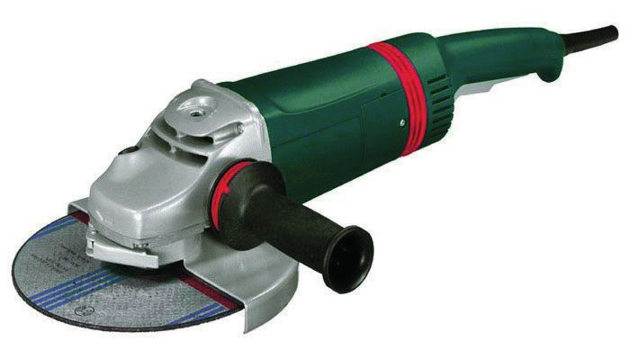
1.     Technical Description of the Horizontal Façade System
1.1 General
       The basic horizontal façade system consists of Trimoterm FTV panels of standard modular widths 1000 and
       1200 mm.

       The range of applications for the horizontal joint façade system is extremely wide. They are suitable for
       business, commercial, leisure, tradeand industrial buildings. The horizontal façade system has excellent
       technical properties, a long life span and allows creative freedom in building envelope design.

       The system of Trimoterm fireproof panels ensures high fire resistance, excellent thermal and sound insulation.
       The panels are used primarily as a facade, partition walls, fire walls and ceilings, or even as a back up panels
       for variety of rainscreen façade systems.

1.2 Panel Profile

               Fig. 1: Trimoterm FTV façade panels
                                                                                                  Side A

                                                                                                             s
                                                                                                   Side B
                                                    600 - 1200

               Fig. 1a: Possible forms of Trimoterm FTV 1000 façade panels

               External Profile Types:

               S - profile (standard profile)
                                                                                                             0.4
                                               50                0.4
                                                                                  50
               V - profile (V)
                                                                                                             1.4
                                       100                                    6.2
                                                                  1.4
                                                                                       100
               V - profile (V2)
                                                                                                             1.4
                                             200                                                  6.2
                                                                  1.4
               Smooth profile (G)

               Micro-lined profile (M)
                                                                                                             0.4
                                   15                            0.4
                                                                        7.5 7.5              15
               Micro-lined profile (M3)
                                                                                                             1.5
                                  30
                                                                 1.5
                                                                              15       15               30

               Internal Profile Types:

               S - profile (standard profile)
                                                                                                             0.4
                                               50                0.4
                                                                                  50
               V - profile (V)
                                                                                                             1.4
                                       100                                    6.2
                                                                  1.4
               V - profile (V2)                                                        100
                                                                                                             1.4
                                             200                                                  6.2
                                                                  1.4
               Smooth profile (G)

               Micro-lined profile (M2)
                                                                                                              1.0
                                        20                       1.0
                                                                          10 10                         20

FTV - Technical Document | EN | Version 6 | January 2021                                                             1
HORIZONTAL FAÇADE SYSTEM TRIMOTERM FTV
Fig. 1b: Possible forms of Trimoterm FTV 1200 façade panels

    External Profile Types:

    S - profile (standard profile)
                        50                                          0.4
                                                                                     50
    V - profile (V)
                        100                                                      6.2
                                                                    1.4
                                                                                          100
    V - profile (V2)
                                200                                                                  6.2
                                                                    1.4

    V - profile (V6)
                                600                                                                  6.2
                                                                     1.4
    Smooth profile (G)

    Micro-lined profile (M)
                                15                                  0.4
                                                                           7.5 7.5              15
    Micro-lined profile (M3)
                                     30
                                                                    1.5
                                                                                 15       15               30

    Internal Profile Types:

    S - profile (standard profile)

                               50                                   0.4
                                                                                     50
    V - profile (V)
                        100                                                      6.2
                                                                     1.4
                                                                                          100
    V - profile (V2)
                                    200                                                              6.2
                                                                     1.4
    V - profile (V6)
                                600                                                                  6.2
                                                                     1.4
    Smooth profile (G)

    Micro-lined profile (M2)

                                20
                                                                    1.0
                                                                            10       10                    20

     Profile Type                         A   B

     S - profile                          •   •
     V - profile (V, V2, V6)              •   •
     Smooth profile (G)                   •   •
     Micro-lined profile (M, M3)          •
     Micro-lined profile (M2)                 •

    Side A is usually the external side of a panel.
    Steel sheet thickness for profile V2, V6, G-gladio is 0.7 mm.

    Note: The arrangement of V profile typically starts in the middle (centred) of the FTV panel module. Module end, grove and the
    distance from the panel edge depends on FTV panel module and may vary. Any other V profile arrangements are declared as
    non-standard and a subject of individual order. Complete panel range can be found in Trimoterm brochure Trimoterm Fire
    proof - Product Range.

2                                                                          FTV - Technical Document | EN | Version 6 | January 2021
HORIZONTAL FAÇADE SYSTEM TRIMOTERM FTV
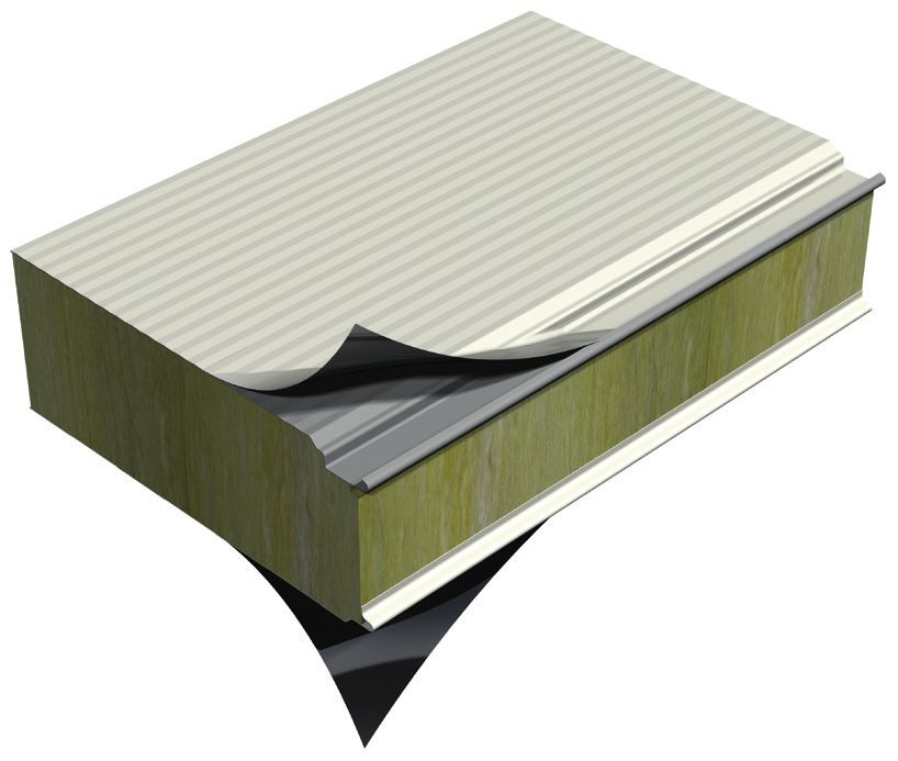
1.3 Panels Composition

       Trimoterm FTV fireproof panels consist of two shallow profiled, coated sheet faces in thickneses of 0.5 mm to 0.7
       mm. The steel sheet is bonded to the panel core made of non-combustible mineral wool lamellas of class A1 (EN
       13501-1). All three layers make a solid panel in a thickness of 50 - 240 mm. Standard width of the panels are 1000
       and 1200 mm. Non standard panel width of 600 -1200 mm can be made by a special request. A protective PVC film
       is applied to the panel surface to protect it during production handling and transport. Panels can be manufactured
       up to 14 m lenght.

1.4    Technical Data
       Table 1: Technical data of Trimoterm FTV 1000 and FTV 1200 façade panels

        Technical data FTV                          FTV 50   FTV 60 FTV 80 FTV 100 FTV 120 FTV 133 FTV 150 FTV 172 FTV 200 FTV 240

        Panel thickness [mm]                           50      60       80      100      120        133          150           172        200      240

        Weight FTV 1000 [kg/m2]     Fe 0,6/Fe 0,6     16,3     17,5    19,9     22,3     24,7       26,3         28,3          31,0       34,3     39,1

        Weight FTV 1200 [kg/m ]2
                                    Fe 0,6/Fe 0,6     16,1     17,3    19,7     22,1     24,5       26,1         28,1          30,8       34,1     38,9

        Cover width [mm]                                                                 1000 and 1200

        Panel length [m]                                                                       up to 14

       Complete Technical data is available in Trimoterm technical specification.

1.5 Coatings
       Steel sheet metal is hot galvanised (net 275 g/m2) in compliance with EN 10346, and additionally protected by
       organic coating in accordance with the coil-coating process (DIN EN 10169/1).

       The following basic types of organic coatings protection are applied to steel sheet metal:
       - based on SP polyester
       - based on PVDF polyvinylidene fluoride
       - based on PUR polyurethane
       - based on PVC polyvinyl chloride, coating or film

       Individual types of organic protection with the basic characteristics are presented in Table 2.

       Table 2: Basic characteristics of an individual type of organic coating or protection

        TYPE OF CORROSION PROTECTION                                    SP       SP      PVDF        PVDF+             PUR            PVC(P)     PVC+F
        Corrosion classification [DIN 55928-8]                           II       III      III             III           III            III        III
        Total organic thickness (my) [EN 13523-1]                       15       25        25              35            50           175-200    120-200
        Temperture resistance (°C)                                     +70       +80      +110            +110          +110           +70        +70
        UV resistance category [EN 13523-10]                            —       Ruv3      Ruv4            Ruv4          Ruv4           Ruv2        —
        Flexibility                                                     ••       ••       •••             ••••         ••••            ••••       ••••
        Staining resistance                                             ••       •••      ••••            ••••         ••••             ••        ••••

       Note:
       •••• suitable without reservations ••• very suitable •• suitable • suitable with reservations/contact Trimo -
       unsuitable
       Note: A detailed explanation of the coating, together with Instructions for the use and maintenance can be found in the
       Technical instructions for the use and maintenance of Trimo products.

FTV - Technical Document | EN | Version 6 | January 2021                                                                                                   3
2   Design procedure
2.1 Panel Thickness Selection

     With respect to the client’s or project requirements or in accordance with the legislation appropriate thickness of
     Trimoterm FTV panel shall be selected. Thickness has a direct influence on the load-bearing capacity of the panel,
     thermal insulation of the façade and heat stability of the structure.

2.2 Structural Design Data

     Advised distances between supports are determined in relation to the selected panel thickness, loads and support
     widths. Panels are structurally weakened where windows, doors and other openings are installled. Exact Structural
     calculation is available by contacting Trimo Technical Support.

2.3 Fixing Methods

     The fixing method is selected according to the structure type.

     For steel structures:
     - A distance profile is welded to a structure and the Trimoterm FTV panel is fixed to it by means of a specially made
       aluminium profile.
     - Trimoterm FTV panel can be fixed directly to a flange if its thickness is not greater than 12 mm.

     For concrete structures the following fixing methods are available for Trimoterm FTV panels:
     - Fixing by a levelling profile for panels of 100 - 240 mm thickness.
     - Fixing by a wide levelling profile for panels of 60 and 80 mm thickness.

           Fig. 2: Load transfer of a weakened panel to adjacent panels

2.4 Sealing

     Special care must be taken when designing sealing material. Local climatiic conditions and internal enviro-
     ments must be taken into account. Trimoterm panels are typicaly factory applied with the required sealing gas-
     kets. In extreme, demanding conditions it may also be essential to apply on site sealing mastic, within the joints.

4                                                                         FTV - Technical Document | EN | Version 6 | January 2021
3      Recommendations for installation
       When erecting a horizontal façade panels must be correctly orientated, to allow water drainage (Fig. 3).

               Fig. 3: Correct panel assembly on horizontal façades

3.1     Removing Protective Foil

       A protective foil, for the protection of colour coated surfaces, against any possible damage caused during transport,
       handling and assembly, is applied to the external face of Trimoterm FTV panels. The foil must be removed from the
       internal face before the installation of an individual panel. The foil on the external side is removed directly before
       the completion of works; it should be removed during the installation where it is necessary, (e.g. in a longitudinal
       joint of two panels, under screws, flashing ...) (Fig. 4). If panels are to be stored for a long period of time, the foil
       should be removed after three months. If panels are to be stored in the open air, they should be protected against
       the sun, if not, the removal of the foil may be problematic.

               Fig 4: Removal of the protective foil

                                                                      NOTE:
                                                                      • Every day, after ending of the installation, the pro-
                                                                         tective foil must be completely removed from each
                                                                         facade element / facade.
                                                                      • If the façade panels are to be stored in the open
                                                                         they should be protected against the sun; otherwi-
                                                                         se the complete removal of foil is no longer pos-
                                                                         sible.
                                                                      • During installation the foil must be removed from
                                                                         all joints of the façade panel.
                                                                      • Façade elements must be protected from water
                                                                         and other liquids seeping into insulation during
                                                                         unloading right through to the end of the instal-
                                                                         lation.

3.2 Elements Cutting

       When cutting panels during assembly, only special scissors, cutting tools and saws that do not heat the
       cutting edge to a high temperature, should be used (Fig. 5). High temperatures can damage the anti-corrosive
       protection, in the immediate surrounding area of a cut. Therefore, the use of any grinding machines is
       prohibited for such purposes! All small metal particles, that appear as a result of cutting and drilling should
       be immediately removed from the panel surface, but certainly when the daily work has been completed.

       Marking and scratching with nails or similar sharp objects can damage the protective coating.

FTV - Technical Document | EN | Version 6 | January 2021                                                                        5
Fig. 5: Elements cutting is allowed with sheet metal shears and saws

          Recommended use                                                                    Restricted use

3.3 Lifting Methods

    It is suggested that special mechanical grippers are used for the assembly of a horizontal façade; these grippers
    can be placed in the longitudinal joint of Trimoterm FTV panel (Fig. 6). Two grippers are needed for one lift and
    they are delivered with panels, when specially ordered. Instructions for the use of grippers will be provided.

          Fig.6: Gripper for the assembly of a horizontal façade

6                                                                        FTV - Technical Document | EN | Version 6 | January 2021
4      Installation Details
4.1.1 Connection to the Main Beam

               Fig. 7: Connection of a horizontal façade to the main beam

                                                                                     View 3D:

                                                                                     Trimoterm FTV

               1. Support angle of the panel-closing element
               2. Panel beam
               3. Dripping edge of a panel
               4. Sealing tape 30x20
               5. Anchor bolt
               6. Blind rivet
               7. Thermal insulation
               8. HF102 aluminium profile
               9. Dripping edge of HF102 profile
               10. Sealing tape 3x15
               11. Blind rivet

       The assembly begins in the final grid line of a building. Before the first panel is fixed, the precision of substructure
       geometry must be checked. Assembly sequence (Fig. 7):
       - A support angle (Item 1) is to be fixed to the concrete main beam at a suitable height that serves as a horizontal
         levelling and riveting of the panel beam.
       - A sealing tape is applied to a façade profile (Item 4).
       - Before fixing of an individual panel, a Z profile is to be fixed for temporary mounting.
       - The panel is to be placed correctly (distance of 40 mm) and fixed to a distance profile over Z profiles, by means of
         self-tapping 6.3x25 screws.
       - The space between two panels is filled with soft mineral wool.
       - Dripping edge of HF102 aluminium-fixing profile is fixed to the foundations of a horizontal façade extension.
       - Cover flashing is fixed over screws; subsequent to a butyl sealing being applied.
       - Front extension of the aluminium fixing profile is to be carried out by a connecting component and sealing (bonding)
         with a polyurethane adhesive (e.g. Sikaflex).
       - The required number of screws per m1 of the aluminium profile is determined by static calculations or in accordance
         with Section 2.3 of Trimo Technical Instructions.

FTV - Technical Document | EN | Version 6 | January 2021                                                                     7
4.1.2 Corner Element Detail

            Fig. 8: Rounded-off corner detail

                                                                                    1. HF102 aluminium profile
                                                                                    2. Sealing tape EPDM 6x25
                                                                                    3. Self-tapping screw
                                                                                    4. Thermal insulation
                                                                                    5. Fixing plate
                                                                                    6. Self-tapping screw 6,3x25
                                                                                    7. Bulb-tite rivet 5,2x19,1
                                                                                    8. Sealing tape 3x15
                                                                                    9. Angular steel profile
                                                                                    10. Bulb-tite rivet 5,2x19,1

            Fig. 9: Preformed sharp-edged corner

                                                                                    1. HF102 aluminium profile
                                                                                    2. Sealing tape EPDM 6x25
                                                                                    3. Self-tapping screw
                                                                                    4. Self-tapping screw
                                                                                    5. Thermal insulation
                                                                                    6. Fixing plate
                                                                                    7. Self-tapping screw 6,3x25
                                                                                    8. Bulb-tite rivet 5,2x19,1
                                                                                    9. Sealing tape
                                                                                    10. Angular steel profile
                                                                                    11. Bulb-tite rivet 5,2x19,1
                                                                                    12. Z profile

     Assembly sequence:
     - Angular steel profile L profile for fixing the rounded corner element and façade panels is initially secured to the
       steel structure.
     - Horizontal arrangement of the panels follows, which are layed horizontally and attached to it.
     - Fixing plates, for temporary mounting, are riveted to the inner side of the vertical radius or horizontal, sharp-
       edged, corner panel (Fig. 8 and 9) and then this pre-assembled panel is fixed to the structure, using a self-
       tapping screw.
     - The space between two panels is filled with soft mineral wool.
     - The aluminium profile is fixed over screws to hold the panels in place.
     - Before fixing the HF102 profile EPDM sealing tape 6x25 mm is applied.
8                                                                        FTV - Technical Document | EN | Version 6 | January 2021
4.2 Fixing a Horizontal Façade to a Steel Structure

       A steel structure, to which panels are fixed, should comply with ENV 1090-1 or Trimo internal requirements.

4.2.1 Installation of a Load-bearing Steel Structure

       Additionally, for classic steel structures, a distance profile (Fig. 10) should be welded to the basic steel structure,
       for a fast and simple installation of a horizontal façade. If the thickness of the load-bearing structure is b < 12 mm,
       fitting of distance profiles is not required (Fig. 11) as it is possible to fix the panels directly.

               Fig. 10: Distance profile

         WARNING:
         A box section 40x40x3 - St 37-2 is used as a distance profile for panel thickness exceeding 100 mm. Steel
         profile U 20x40x20x3 - St 37-2 is used as a distance profile for panel thickness 60 and 80 mm. A distance
         profile IS NOT NECESSARY when steel structure of < 12 mm is used (Fig. 11).

4.2.2 Fixing a Horizontal Façade to a Steel Structure using HF102 Aluminium Fxing Profile

               Fig. 11: Fixing of a horizontal façade to a steel structure, depends on the thickness of substructure

                                                                                                         1. HF102 aluminium fixing profile
                                                                                                         2. Sealing tape EPDM 6x25
                                                                                                         3. Self-tapping screw
                                                                                                         4. Thermal insulation
                                                                                                         5. Rectangular steel tube 40x30x3
                                                                                                         6. Bulb-tite rivet 5,2x19,1
                                                                                                         7. Z profile
                                                                                                         8. Sealing tape 3x15
                                                                                                         9. Self-tapping screw 6,3x25
                                                                                                         10. U profile
                                                                                                         11. Z profile
                                                                                                         12. Fixing plate

                                                                                                         NOTE:
                                                                                                         Distance between HF profile and
                                                                                                         Trimoterm panel needs to be 1 - 3 mm.

FTV - Technical Document | EN | Version 6 | January 2021                                                                                     9
Fig. 12: HF102 aluminium fixing profile.

           HF102/1                                                       HF102/2

           painted                                    painted                             painted

4.2.3 Temporary Fixing

     The temporary fixing of panels when placing the panels to the horizontal façade should be fixed in the short
     term, to the hot-rolled steel profiles.

     To accomodate this temporary fixing, profiles (Z profile) are inserted by pressing between the core and the
     inner steel sheet of the panel and then fixed with 2 4x8 mm stainless steel rivets (Fig. 13). Panels are installed
     correctly when the opening in the vertical joint is 40 mm. Panels are fixed to the sub-structure through
     temporary fixing profiles with self-tapping screws 6,3x25 as follows:
     - in central area - 1 piece / panel,
     - edge area, buildings with side openings - 2 pieces / panel,
     - areas with wind loads higher than 0.5 KN/m2 - 2 pieces / panel.

     After the completed installation, each individual, vertical joint should be concealed by fixing a HF102
     aluminium profile.

           Fig. 13: Temporary mounting.

           External face of a panel

                                                          1. Panel Trimoterem FTV
                                                          2. Fixing Z element
                                                          3. Blind rivet

           Fig. 14: Profiles types for temporary fixing (profile length: 120 mm)

           a) FTV 100 - FTV 150                         b) FTV 60 - FTV 80               c) For fixing without a distance profile (b < 12 mm)

10                                                                                 FTV - Technical Document | EN | Version 6 | January 2021
Fig. 15: Erection of a 100, 120, 150 and 200 mm thick panels

               Fig. 16: Erection of panels in thickness types 60 and 80 mm

               Fig. 17: Temporary mounting (1 piece / panel)

                                                                   1.   Panel Trimoterm FTV
                                                                   2.   Load-bearing steel structure
                                                                   3.   Distance profile
                                                                   4.   Fixing Z profile 40x__x40x2
                                                                   5.   Self-tapping screw 6.3x25

FTV - Technical Document | EN | Version 6 | January 2021                                               11
4.2.4 Assembly of Aluminium Profiles

                    Assembly of HF102 Aluminium Fixing Profile

                    Sealing tape EPDM 6x25 (Fig. 18) should be applied to the HF102 aluminium fixing profile prior to installation.
                    Please note that a seal must be applied to the profile edge.

                           Fig. 18: Position of sealing tape on the HF102 aluminium profile

                                                                                                                                                                                                 Cutting profiles to a required length, should be
                                                                                                                                                                                                 carried out by a suitable portable saw with a
                                                                                                                                                                                                 function that accommodates variable cutting
                                                                                                                                                                                                 angles. The deviation allowed is ± 0.5 mm at the
                                                                                                                                                                                                 width of 102 mm.
                                                                                                        2 pcs/joint

                                                                                                                          1 pcs/joint
                                                                                          cartr.

                                                                                                                                                                                                 1.       Fixing extrusion
                                                                                                   m²
                                                                      m

                                                                                                                      m

                                                                                                                                        m

                                                                                                                                             m
                                                                                                                                                                                                 2.       Self-adhesive sealing tape 6x25xL
                                                                             2 6 4 5 7 3 1 2                                                                                                     3.       Prolongation flashing
                                                                                                                                                                                                 4.       Thermal insulation
6 3                                                                                                                                                                                              5.       Rivet 4x10
                                                                                                                                                                                                 6.       Mastic sealant
 1 pcs/joint

                                                                                                                                                                                        2 pcs/joint

                                                                                                                                                                                                                    1 pcs/joint
                                                                                                                                                                                                 7.       Decorative extrusion
                                                                                                                                                                cartr.

                                                                                                                                                                                   m²
                                                                                                                                                       m

                                                                                                                                                                                                               m

                                                                                                                                                                                                                                            m

                                                                                                                                                                                                                                                      m
                                                                                                                                                                          2 pcs/joint

                                                                                                                                                                                                      1 pcs/joint

                                                                                                                                                                                                                                          m gap
                    Joining of HF102 aluminium
                                             m fixing profiles
                                               2
                                                                                                                                                       cartr.

                                                                                                                                                          2 6 4 5 7 3 1 2
                                                                                                                                                                  m²
                                                                                                                                                 m

                                                                                                                                                                                            m

                                                                                                                                                                                                                                                  m
                                                                                                                                                                                                                         Thermal dilatation
                                                                                                    1 pcs/joint
                           Fig. 19: Connecting aluminium3element                                                                                   2 6 4 5 7 3Fig.120:2Installation of a connecting element
                                  5 6 3
                         45

                                                     m
                                                        1
                                                            cartr.

                                                                            1 pcs/joint
                                              2 pcs/joint

                                5 6 3              Step 7
                                                     m  1                                                                                                 Step 2
                                             cartr.

                                                               m
                                                           1
                                                              1 pcs/joint
                               2 pcs/joint

                                                                                                                                                 45°
                                                                                                                                                    sea

                                                                                                                                                                                                                                                              Thermal dilatation gap
                                                                                                                                                       ling
                                                                                                                                                                                     m
                                                           3
                                                             1 pcs/joint                                                                                        tap
                                                                                                                                                                     ec                 2         m
                                                                                                                                                                           ut
                                                                                                                                                                                                      1

                                                                                                                                                                                                                                                          Thermal dilatation gap
                                                                                                                                                                             1 pcs/joint
                                                                                                                                                                                 m
                                                                                                                                                                                      2 3         m
                                                                                                                                                                                                      7
                                                                                                                                        45

                                                                                                                                                                                     m
                                                                                                                                                                         1 pcs/joint
                                                                                                                                                                                      3 1
                                                                                                                                   45

                                                                                                                                                                                     m
                                                                                                                                                                                      17
                                                                                                                                                                                 m
                                                                                                                                                                                               m
                                                                                                                                                                                 m
                                                                                                                                                                                      7 1 1 pcs/joint
                                                                                                                                                                                        13
                                                                                                                                                                                            m                                                                                              m
                                                                                                                                                                                          1 pcs/joint
                                                                                                                                                                                                                                                                                             1
                                                                                                                                                                                        3                                                                                                  m
                                                                                                                                                                                                                                                                                       m
                                                                                                                                                                                                                                                                                           17
                                                                                                                                                                                                                                                                                       m
                                                                                                                                                                                                                                                                                           7

                    Step 1		   Apply the mastic seal (pos.6) in two longitudinal and transversal stripes on prolongation flashing
                    		         (pos.3). Install prolongation flashing (pos.3) with mastic seal on the Alu profile (pos.1) and fix it with a
                    		         rivet (pos.5).
                    Step 2		   Install the self adhesive sealing tape EPDM 6x25xL (pos.2) on inner side of the Alu fixing profile (pos.1).
                    		         Prolongation of self adhesive sealing tape EPDM 6x25xL (pos. 2) must be done at angle of 45°.

                      NOTE:
                      Thermal dilatation gap on prolongation must be minimal 1 mm/1 m of profile +2 mm.

               4.3 Fixing a Horizontal Façade to a Concrete Structure

                    The concrete structure onto which panels are to be fixed should comply with ENV 13670-1 or/and Trimo internal
                    requirements.

               4.3.1 Fixing a Horizontal Façade by a Levelling Profile

                    Fig. 21: presents a fixing method by levelling the base. This method is useful for Trimoterm FTV panels of
                    higher thickness (100, 120, 150, 200 and 240 mm). Dimensions of the levelling profile are presented in the
                    Trimo standard details.

               12                                                                                                                                                                                                   FTV - Technical Document | EN | Version 6 | January 2021
Fig. 21: Fixing a Trimoterm FTV panel horizontal façade using a levelling structure

                                                                                 1. HF102 aluminium profile
                                                                                 2. Sealing tape EPDM 6x25
                                                                                 3. Self-tapping screw
                                                                                 4. Anchor bolt
                                                                                 5. Thermal insulation
                                                                                 6. Bulb-tite rivet 5,2x19,1
                                                                                 7. Leveling plate
                                                                                 8. Z profile
                                                                                 10. Sealing tape EPDM 3x20
                                                                                 11. Self-tapping screw 6,3x25

4.3.2 Fixing a Horizontal Façade using Adjustable Substructure system HMP 2

       The adjustable substructure system is used to level out the main structure of the building or supporting wall, in
       order to install the Trimoterm FTV façade system. Image 27 demonstrates the detail of adjustable substructure.

               Fig. 22: Assembly mounting of Trimoterm FTV panels using a HMP 2

                                                                                 1. HF102 aluminium profile
                                                                                 2. Sealing tape 6x25
                                                                                 3. Self-tapping screw
                                                                                 4. Self-tapping screw 6,3x25
                                                                                 5. Thermal insulation
                                                                                 6. U bracket HMP-B
                                                                                 7. Sealing tape 3x15
                                                                                 8. Bulb-tite rivet 5,2x19,1
                                                                                 9. Fixing plate
                                                                                 10. C steel beam HMP-A
                                                                                 11. Anchor bolt
                                                                                 12. Self-tapping screw 6,3x25

         NOTE:
         The following advice applies to fixing described in Sections 4.3.1 and 4.3.2:
         - Suitable evenness of the overlying surface is assured by a levelling structure of a façade.
         - Distances between anchor screws must be determined in accordance with a static calculation, relating to
         the properties of the building, wind loading, anchor type and the quality of the load-bearing structure.

FTV - Technical Document | EN | Version 6 | January 2021                                                             13
TRIMO D.O.O.
PRIJATELJEVA CESTA 12,
8210 TREBNJE, SLOVENIA
T: +386 (0)7 34 60 137
F: +386 (0)7 34 60 127
                                                                                                                                                                                                                                                       Published by: Trimo d.o.o., EN / 01/2021

TRIMO@TRIMO-GROUP.COM
WWW.TRIMO-GROUP.COM

Trimo Group holds full copyrights on the information and details provided on this media, therefore any unauthorized reproduction and distribution is strictly prohibited. Professional care has been taken to ensure that information/details
are accurate, correct and completed and not misleading, however Trimo, including its subsidiaries, does not accept responsibility or liability for errors or information, which is found to be misleading. Information/details on this media
are for general purposes only. Use of it is on your own initiative and responsibility for compliance with local laws. Any deviations in details and project solutions are user responsibility. In no event, will we be liable for any loss or damage
including without limitation, indirect or consequential loss or damage, or any loss or damage whatsoever arising from loss profits arising out of or in connection with, the use of this media. All information issued by Trimo Group is
subject to continuous development and information/details contained on this media are current at date of issue. It is user`s responsibility to obtain most up-to-date information from Trimo when information/details are used for project.
The last version of the document is available on www.trimo-group.com. Latest version of published document in English language prevails over other translated language documents.
For information about the delivery of panels see Trimo’s General conditions (https://trimo-group.com/en/trimo/general-conditions-of-sales).
You can also read