CONTAINER INSTALLATION MANUAL - Victory-Marine
←
→
Page content transcription
If your browser does not render page correctly, please read the page content below
CONTAINER INSTALLATION
                                   MANUAL

                                             VICTORY MARINE d.o.o. Pula
52 100 Pula – Kandlerova 8 MBS: 040312722 - OIB: 16773172388 Tel/*Fax: +385 /0/ 52 384 511 / GSM: + 385 /0/99 325 6325 EMAIL:
                                    info@victory-marine.hr / WEB: www.victory-marine.hr

                                                             1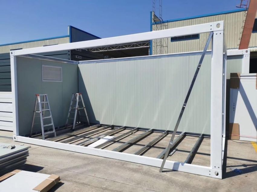
INSTALLATION INSTRUCTIONS

The installation process requires min. three persons with technical skills. It is recommended to wear protective
clothing, including a helmet and gloves.

IMPORTANT

Foundation preparation

The ground must be properly leveled, and the foundation is made of concrete or
with the wooden base.

It is not necessary to build the foundation on a full base, as shown in Image 1, it is sufficient
 to set it on six concrete pillars - four in the corners and mandatory one extra in the middle
 of each side. In this way, a good bearing capacity of the structure will be ensured.

The foundation must be suitable for carrying a load capacity of up to 1.8 tons!
                                                                                                    Image 1. Foundation on
                                                                                                            concrete pillars

Look at the example of the foundation using concrete blocks filled with cement and cemented to a gravel terrain to
ensure stability of the container (Image 2).

                             Image 2. Foundation made of concrete blocks filled with cement.

    Step 1. Installation of the bottom and top main frame

                            Image 3. Properly positioned frame should look like this.
                                                            2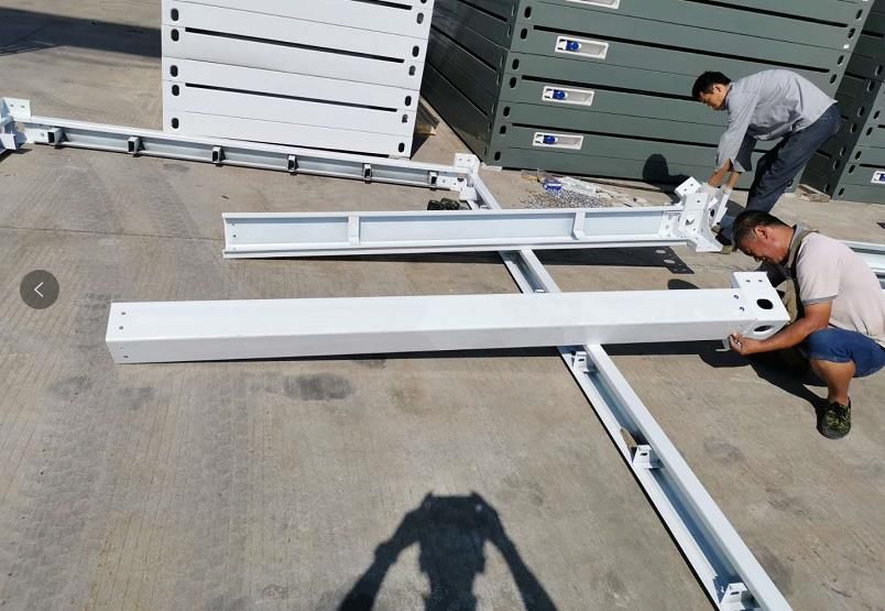
Item 1.1 Bottom side beam                            Item 1.2 Bottom cross beam
       160*55*2680mmm (for unit length 2400mm)              160*55*2008mm (for unit length 2400mm)
       160*55*5630mm (for unit length 3000mm)               160*55*2680mm (for unit length 3000mm)

                                           Image 4. Bottom frame beams.

         Item 1.3 Top side beam                              1.4 Top cross beam
         160*55*2680mm (for unit length 2400mm)              160*55*2008mm (for unit length 2400mm)
         160*55*5630mm (for unit length 3000mm)              160*55*2680mm (for unit length 3000mm)

                                             Image 5. Top frame beams.

    1.) Installation of the bottom main frame

You will need the following components:
    1. Corner fitting (Item: 1.6) - 4 pcs
    2. Bottom side beam 5630mm (Item: 1.1) - 2 pcs
    3. Bottom cross beam 2680mm (Item: 1.2) - 2 pcs

Connect these components using the connecting screws, as shown in Image 6.

                         Image 6. Connect the bottom side and cross beams with corner fittings.

                                                        3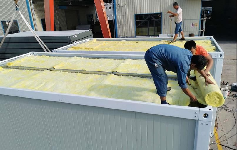
2.) Measure the diagonal line with the meter and make sure that the bottom frame is of a rectangular
shape, and then tighten the bottom frame.
Image 7. Correctly adjust diagonals from every angle to get a regular rectangle.
Image 8. The bottom frame should look like a regular rectangle.
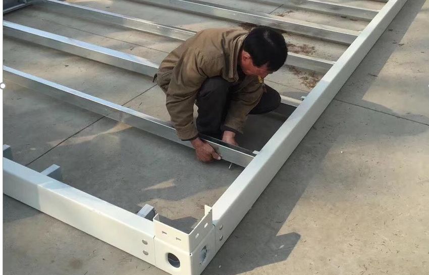
3.) Connect the square cross tubes to the bottom main frame
You will need the following components:
1. Steel tube 40 * 80mm (Item: 2.2) - 5 pcs
2. Steel tube 80 * 80mm (Item: 2.1) - 4 pcs
Cross steel tubes are inserted into the grooves on the side bottom beams. They are arranged by stacking, one
narrower following one wider, ending with a narrower tube, as shown in Image 9.
Use screws to connect them (12*60mm) to the bottom main frame.
4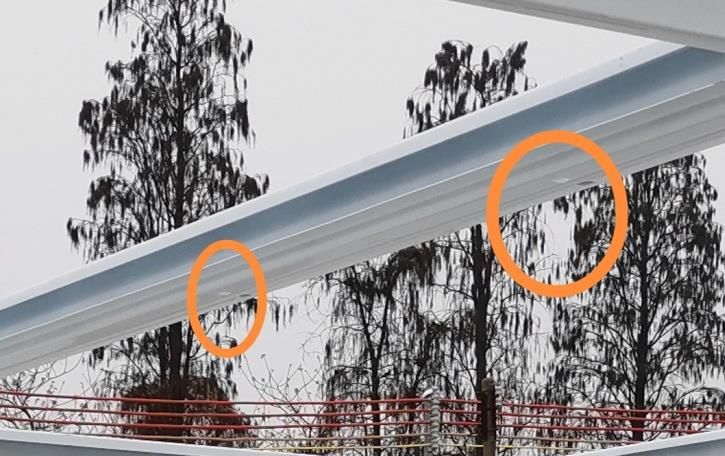
Image 9. Stacking of side cross steel tubes.

                          Image 10. Cross steel tubes form a ribbed bottom structure.

    4.) Connect four angular beams (columns) to the bottom main frame

You will need the following components:
          1. Corner fitting (Item: 1.6) - 4 pcs
          2. Angular beam (column) 2480mm (Item: 1.5) - 4 pcs

Connect the angular beams (columns) with the corner fittings to the bottom main frame and use the connecting
screws as in Image 11, but do not tighten them.

                                                       5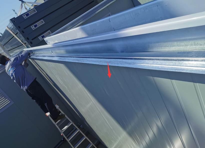
Image 11. Connection of beam columns with corner fittings.

Image 12. Do not tighten the screws on the corner fittings.

                            6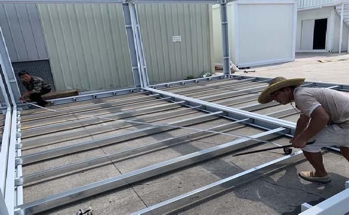
This hider is placed on the inside, in the
                                                                   middle and in the bottom and top corner of
                                                                   each column and is used for fixing the wall
                                                                   panel. Use screw to connect the wall panel
                                                                   with the hider through the beam column
                                                                   (Image 13).

                      Image 13. Hiders inside the columns are used to tighten the wall panel.

    5.) Connect the top main frame

You will need the following components:
    1. Top side beam 5630mm (Item: 1.3) - 2 pcs
    2. Top cross beam 2680mm (Item: 1.4) - 2 pcs

Connect the top side and cross beams with corner fittings to form the top main frame and place them on the angular
beams (columns). Use screws to connect them, but don't tighten.

    6.) Adjust bottom and top frame

    1.   Bottom frame: Measure the diagonal line from all sides to confirm the measures to ensure the stability of
         the structure, then tighten all the screws on the columns.

                                                        7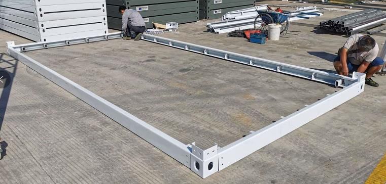
Image 14. Diagonal of the bottom main frame is measured with meter.

2.   Top frame: Make sure that the holes on the top beams (red indicated in Image 15), used for water drainage,
     are directed downwards (towards the floor). Check with the measuring level (Image 15) and adjust the
     frames if necessary.

                           Image 15. Construction check with measuring level.

                                                     8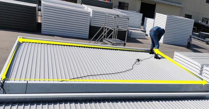
Step 2. Installation of wall sandwich panels, windows and doors
1.) Cut window and door openings on the wall panels according to the size of the container unit.
There are two sizes of container units available:
1. Standard unit: 5950*3000*2800mm consists of 16 panels 950mm wide:
a) 15 pcs panels dimensions 2560*950mm
b) 1 pcs panels dimensions 3190*950mm - this panel has to be cut into 5 small parts as follows:
Panel above door 470*950mm - 1 pcs
Panel by the window 900*950mm - 2 pcs
Panel by the window 460*950mm - 2 pcs
15 PCS x + 1 PCS x
Image 16. Stacking panels on a standard unit.
2. Smaller unit: 5950*2400*2800mm consists of 14 panel dimensions 2560*1150mm:
Window dimension - 925*1200mm
Door dimension - 925*2035mm
Image 17. Stacking panels on a smaller unit.
Mark the line of the desired dimension of the door on the door panel and use a hand mill to cut them correctly.
In the same way cut the window panel, as shown in Image 16 and Image 17.
Note: It is recommended to cut the openings for windows and doors in full panel. Windows and doors should not
be placed over multiple panels to ensure insulation.
9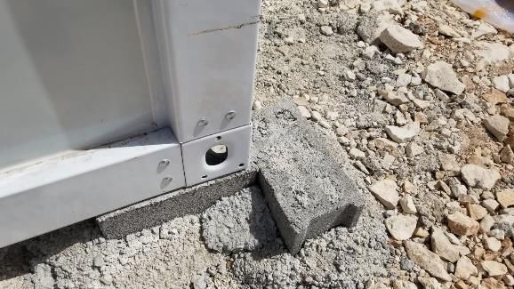
2.) Connect the wall panels with the connecting grooves.

        The wall panels have connecting grooves and are clasped together one by one. For the ending wall panel
        near the column, use screws to fix it to the side column holder.

                                Image 18. Wall panels are connected by grooves.

                                             It is recommended to connect first wall
                                             panels on the longer side of the wall, the one
                                             without windows and doors (Image 19).

Image 19. Connecting wall panels.

                                                      10
3.) Installation of the U-groove profile on side wall panels
1. Place waterproof strip on U-groove profiles
Waterproof strip (Item: 7.4) is placed on the U-groove profile (Item 7.6.1) to create a slope for water
drainage (Image 20). One package of waterproof strip is enough for two U-groove profiles.
Glue the waterproof strip to the U-
groove profile. This rubber strip is used
to prevent water leakage.
Image 20. Placing the waterproof strip on the U-groove profiles. Image 21. Fixing U-groove profile with screws.
For better stability make sure to fix U-groove profiles with the top frame beams with screws, as in Image 20.
2. Set the U-groove profile
When the longer side of the wall (5950mm) is well fixed, insert the U-groove profile 5740mm (Item 7.6.1) on
the top of the wall panels on both sides. The U-groove profile (Image 22) is used for fixing wall panels and also
for fixing and holding top purlines which will be installed in Step 4.
Image 22. U-groove profile is set on the longer side of the construction.
114.) Installation of U-groove profiles on cross wall panels
When the shorter side of the wall (3000mm) is well fixed, insert the U-groove profile 2800mm (Item 7.6.2)
on the top of the wall panels on both sides. This U-groove profile is used for fixing wall panels on the cross
sides and also for fixing and holding top purlines which will be installed in Step 4.
Image 23. U-profile on the cross side of the structure.
5.) Installation of windows and doors
Please place the windows and doors correctly in the desired places. Windows and doors can be installed
anywhere as desired.
Note: Position the door frame (Item7.1) in the place where door will be installed, and then install the door
next to the door frame (Image 24).
Image 24. Door frame.
12Position the door frame (Item 7.1) inside of the
blue line (Image 25) to prevent excessive impact
of the door on the stability of the wall panel.
Image 25. Correctly placed door frame.
The door frame (Item 7.1) should be fixed
inside the wall next to the door (Image 26).
Image 26. Inside view of the door frame.
Step 3. Installation of the MGO floor boards or MGO floor boards with glue decoration
Take 5 pcs of MGO boards (Item: 4.1) and place them on the floor structure, make sure that the MGO boards are
well placed next to the wall panels.
To fix the MGO boards, use a 3.2*32 flat-headed screw.
Image 27. Properly positioned MGO boards.
13Step 4. Top installation of the container house
1.) Installation of the top cross beam square tubes (top purlines)
You will need the following components:
1. Top cross beam square tube 50*50*2790mm (Item: 2.3) - 2 pcs
2. Top cross beam square tube 40*80*1880mm (Item: 2.4) - 3 pcs
3. Top cross beam square tube 40*60*1880mm (Item: 2.5) - 6 pcs
Connect the top purlines to the U-groove slots on the side (Item 7.6.1) with the U-profiles of the cross side (Item
7.6.2).
Mount the top purlines as shown in Image 28:
Image 28. Installation of top purlines.
Tighten the top purlines well with screws (Image 29).
Image 29. Screws under the top purlines.
142.) Installation of the interior ceiling - interior ceiling length 2790mm (for unit 3000mm)
You will need the following components:
Interior ceiling panels 900*2950*0.286mm (Item: 5.1) - 6 pcs
Place the interior ceiling panels (Item: 5.1) on the top cross square tube beams (top purlines).
Secure them well with nails on each top of the cross beam.
Image 30. Installation of ceiling panels.
Fix the panels on the equal distance.
Image 31. Fixing ceiling panels with nails.
15Properly finished ceiling should look like in Image 32:
Image 32. Properly finished ceiling.
3.) Installation of insulation on top of the ceiling panels
Place the glass wool (Item: 5.3) on top of the ceiling panels to ensure thermal insulation.
Image 33. Installation of glass wool is used for thermal insulation.
4.) Installation of roof tile panels
You will need the following components:
Roof tile panels 2950mm - 6 pcs
Note: The roof tiles are slightly wider than the width of the frame so that the edges can be bent with a lever and
fastened to the U-groove beam. This will ensure better water resistance (Image 35).
16Note: Nails can only be used for fixation on the top main frame, along yellow lines (Image 34), otherwise they will
cause leakage through the tiles! Use silicone for any tile connection.
Use silicone or
special mounting
foam for roof tiles
Image 34. Fixing with nails is allowed only on the main frame. Image 35. Silicone for roof tiles
When stacking roof tile panels, put silicone under each panel.
Do not cut the roof tiles in order to
bend the edges later with a lever
(Image 36).
Image 36. Bending roof tile edges with a lever.
Note: Use white silicone to cover small holes on self-tapping screws to prevent water leakage (Image 37).
Image 37. Self-tapping screws are covered with silicone for leakage protection.
17Step 5. Installation of accessories
1.) Install the skirting for internal corner molding (Item: 7.2). Set the skirting like shown in Image 38:
Item 7.2 Internal corner molding
Image 38. Internal corner skirting.
2.) External finishing with silicone around panels edges and around the openings
Use white silicone (Item: 7.3.9) to silicone all the edges around all openings and wall panels from all sides in
order to protect them from moisture, as shown in Image 39:
The silicone should be of a circular
shape.
Image 39. Finishing with white silicone.
Congratulations you have finished the installation of your first container unit!
18How to combine two modules together?
Note: Preparation for additional units is made before installing wall panels!
1. Preparation for additional containers:
Drill holes in the corners of attaching containers, in the place of the connection (Image 40).
Image 40. Screws in the corner fitting.
2. Attaching additional units
The floor level is raised with square tubes:
1.) Ground connection of containers, side by side: For each container, place 8 pcs of cross square tubes to
raise the floor level. For each container you need 2 pcs 40*60mm square tubes and 6 pcs 40*40mm
square tubes.
Image 41. Raising the floor level. Image 42. Square tubes – T-purlines.
Another solution to raise the floor level is to fix the 40 * 60mm square tubes on the outside with T-purlines as in
Image 42. In this case, use the 40 * 40mm square tubes only on the cross beams (2400mm / 3000mm), on the
starting and ending side.
192.) Connection of containers on top of each other (second level): After installing the main frame and
purlines, use the connection key to lock the corner fittings of the combined modules together (Image 43).
Image 43. Combined units, connecting key.
Lock with the connecting key and tighten with screws through the corner fitting. The connection on the
outside should look like in Image 43.
3. Place skirting to cover the columns and top frames (Image 44).
These skirting also serve as a water drainage system.
Image 44. Ceiling skirting.
20Important:
Drainage system:
1. For one standard unit:
On both top side beams there are four holes (Image 45). Accordingly there are eight holes in total through which
water flows towards the floor.
Image 45. Drainage holes on the top side beams.
2. For combined units (two or more connected modules):
The water will enter in the top skirting and flow towards the floor through the side skirting on the column beams.
Image 46. Drainage holes on the skirting on the top side beam.
Image 47. Drainage system for combined units.
21Instruction for skirting installation:
The top skirting should cover the line marked with number 1 in Image 48 and
skirting on side beams should cover the line marked with number 2 in Image
48, on both sides.
For combined units, place 1 is the lowest point through which most of the
water will flow through the top skirting.
In this way, the water will enter the top skirting and go down the side skirting
to exit through the corner fittings.
Image 48. Properly placed drainage skirting.
Notes:
1.) Cut the square openings around the side skirting on the floor to leave room for water drainage through the
side skirtings, as in Image 49.
We recommend to cut out the part of the lower
beams which connects to the side skirtings in order
for the water to flow freely into the floor (the place
is marked in (Image 49).
Image 49. Water flows outside through the side skirting through the floor.
2.) The top skirting is connected by screws to the ceiling, fix them on each side. Never cut the ceiling down the
middle or drill holes in it.
3.) In the place where the top and side skirting lines connect, make a line with silicone to prevent water leakage.
4.) Two red arrows in Image 50 show a side skirting connected to a wall panel. Silicon well on each side of both
side skirtings and the angular connection of the top and side skirtings to prevent water leakage, as in Image
50.
The top skirting should be done after the basic
structure is fixed well, including all the ceilings and
top tiles. The combined top skirting is installed first
and then skirtings for the columns.
Image 50. Siliconing of the side skirtings and the angular connection of the top and side skirtings.
225.) The side skirtings should enter in the square openings on the floor. Use silicone to prevent water leakage,
as in Image 51.
Image 51. Silicone around the connection of the side skirting with the floor.
How to add a partition wall?
1. Fix the U-groove profile onto the floor with screws
2. Fix the wall into the U-groove profile
3. Fix the wall on the ceiling with the accessories for internal corner molding (Item 7.2)
Image 52. U-groove profile for the floor.
Connect the transitions between modular units with the floor skirting.
Image 53. Floor skirting
231. Material List
No Item Material Description Image Remark
Dimensions Item Quantity
1.1 Electrolytic
Bottom side beam, Iron &Power
bending steel plate 160*55*5630mm 2 Coated
Thickness 2.5 mm
Bottom steel 1.2
1 Electrolytic
frame Bottom cross beam,
bending steel plate 160*55*2680mm Iron &Power
160*55*2008 mm 2 Coated
1.3
Electrolytic
Top side beam, Iron &Power
bending steel plate 160*55*5630mm 2 Coated
Top steel frame
2 1.4
Top cross beam, Electrolytic
flexible steel plate 160*55*2680mm Iron &Power
160*55*2008 mm 2 Coated
1.6 Power
Coated
Corner Angular elements, Steel:160*160*160*4.0mm
3 fittings flexible steel plate 8
, white
1.5
Electrolytic
Column steel:160*160*2480*2.3mm, Iron &Power
4 Column bending white 4 Coated
steel plate
2.1
Square tube 80*80*2990mm 4 Electroly
80*80*2390 mm tic Iron
5 Bottom cross &Power
2.2
Beam Coated
Square tube 40*80*2990mm 5
40*80*2390 mm
2.3 Power
Coated
Square tube 50*50*2800mm 2
50*50*2190 mm
2.4
6 Top cross beam
Square tube 40*80*1880mm 3
2.5
Square tube 40*60*1880mm 6
50mm double paint coated
7 EPS panel steel EPS panel full set
Wall panel (steel:0.326mm, density:
12kg)
24900*2950*0.286 mm 5.1 6 pcs
8 Ceiling Interior ceiling Thickness 0.286mm
5.3
Thickness 50mm Glass
9 Roof insulation Glass wool Full set
wool, density 10KG /m³
7.4
Waterproof tape 0.476 mm
10 Roof 1.2 mm groove side length 7.6.1
U-groove profiles 5740 mm
2800mm cross length
U-groove profiles 2200mm cross length 7.6.2
4.1
11 Floor MGO Panel 1147*2790*15mm MGO 5 sets
Fireproof plate
7.1
Door frame
12 Door 1 set
One door, size 925*2035mm,
Steel door steel, flat, white
13 Window Aluminum Windows Aluminum Safety 2 sets
window 925*1200mm
Window and door
frame, angular full set
aluminum, wall
14 Accessories grooves, angular
skirting board 7.2
Screws, glue, screw,
glue full set
252. Installation tools
Name Image Usage Remark
Drill holes for
self- tapping Accessories
Hand drill
screw, drill needed
other holes
4.2MM drill head
Accessories
for hand
drilling
Self-tapping
screw sleeve
Rivert gun To fix rivert
With Cutting
pieces and
Hand mill
Polished
sheet
Cutting
With cutting
board
metal piece
machine
26To install
Glue gun
glue
Scissors
For top
Ladder 2 pcs
Montage
VICTORY MARINE d.o.o. Pula
52 100 Pula – Kandlerova 8 MBS: 040312722 - OIB: 16773172388 Tel/*Fax: +385 /0/ 52 384 511 / GSM: + 385 /0/99 325 6325
EMAIL: info@victory-marine.hr / WEB: www.victory-marine.hr
27You can also read