AOS-CX 10.07 Quality of Service Guide - 8360 Switch Series
←
→
Page content transcription
If your browser does not render page correctly, please read the page content below
AOS-CX 10.07 Quality of
                         Service Guide
                          8360 Switch Series

Part Number: 5200-8165
Published: April 2021
Edition: 1
Copyright Information
© Copyright 2021 Hewlett Packard Enterprise Development LP.
Open Source Code
This product includes code licensed under the GNU General Public License, the GNU Lesser General Public
License, and/or certain other open source licenses. A complete machine-readable copy of the source code
corresponding to such code is available upon request. This offer is valid to anyone in receipt of this
information and shall expire three years following the date of the final distribution of this product version
by Hewlett Packard Enterprise Company. To obtain such source code, send a check or money order in the
amount of US $10.00 to:
Hewlett Packard Enterprise Company
6280 America Center Drive
San Jose, CA 95002
USA
Notices
The information contained herein is subject to change without notice. The only warranties for Hewlett
Packard Enterprise products and services are set forth in the express warranty statements accompanying
such products and services. Nothing herein should be construed as constituting an additional warranty.
Hewlett Packard Enterprise shall not be liable for technical or editorial errors or omissions contained herein.
Confidential computer software. Valid license from Hewlett Packard Enterprise required for possession, use,
or copying. Consistent with FAR 12.211 and 12.212, Commercial Computer Software, Computer Software
Documentation, and Technical Data for Commercial Items are licensed to the U.S. Government under
vendor's standard commercial license.
Links to third-party websites take you outside the Hewlett Packard Enterprise website. Hewlett Packard
Enterprise has no control over and is not responsible for information outside the Hewlett Packard
Enterprise website.
Acknowledgments
Intel®, Itanium®, Optane™, Pentium®, Xeon®, Intel Inside®, and the Intel Inside logo are trademarks of
Intel Corporation in the U.S. and other countries.
Microsoft® and Windows® are either registered trademarks or trademarks of Microsoft Corporation in the
United States and/or other countries.
Adobe® and Acrobat® are trademarks of Adobe Systems Incorporated.
Java® and Oracle® are registered trademarks of Oracle and/or its affiliates.
UNIX® is a registered trademark of The Open Group.
All third-party marks are property of their respective owners.
|2Contents
Contents
Contents 3
About this document 5
Applicable products 5
Latest version available online 5
Command syntax notation conventions 5
About the examples 6
Identifying switch ports and interfaces 6
QoS overview 8
End-to-end QoS behavior 8
Best effort service 8
Class of Service 8
Differentiated services 9
QoS on the switch 10
QoS trust 11
Dynamic QoS trust mode 12
Port rate limiting 12
Queue profiles 13
Schedule profiles 13
Egress queue shaping 14
Egress port shaping 14
Explicit Congestion Notification 15
Threshold profiles 15
Terms 15
QoS configuration 17
Configuring QoS 17
Configuring expedited forwarding for VoIP traffic 17
Configuring rate limiting 18
Configuring egress queue shaping 20
Configuring egress port shaping 20
Supporting Ethernet 802.1D Class of Service 21
Monitoring queue operation 22
QoS commands 23
apply qos 23
apply qos threshold-profile 24
dwrr queue 25
map queue 25
min-bandwidth 27
name queue 27
qos cos 28
qos cos-map 29
qos dscp 30
qos dscp-map 31
qos queue-profile 33
qos schedule-profile 34
qos shape 35
AOS-CX 10.07 Quality of Service Guide | (8360 Switch Series) 3qos threshold-profile 36
qos trust 37
queue action 38
rate-limit 39
rate-limit 40
show interface queues 42
show interface qos 43
show qos cos-map 44
show qos dscp-map 45
show qos queue-profile 46
show qos schedule-profile 47
show qos threshold-profile 48
show qos trust 49
strict queue 50
Support and Other Resources 52
Accessing Aruba Support 52
Accessing Updates 52
Aruba Support Portal 52
My Networking 53
Warranty Information 53
Regulatory Information 53
Documentation Feedback 53
Contents | 4Chapter 1
About this document
About this document
This document describes features of the AOS-CX network operating system. It is intended for administrators
responsible for installing, configuring, and managing Aruba switches on a network.
Applicable products
This document applies to the following products:
n Aruba 8360 Switch Series (JL700A, JL701A, JL702A, JL703A, JL706A, JL707A, JL708A, JL709A, JL710A,
JL711A)
Latest version available online
Updates to this document can occur after initial publication. For the latest versions of product
documentation, see the links provided in Support and Other Resources.
Command syntax notation conventions
Convention Usage
example-text Identifies commands and their options and operands, code examples,
filenames, pathnames, and output displayed in a command window. Items that
appear like the example text in the previous column are to be entered exactly
as shown and are required unless enclosed in brackets ([ ]).
example-text In code and screen examples, indicates text entered by a user.
Any of the following: Identifies a placeholder—such as a parameter or a variable—that you must
n substitute with an actual value in a command or in code:
n
n For output formats where italic text cannot be displayed, variables are
n example-text
enclosed in angle brackets (< >). Substitute the text—including the
n example-text
enclosing angle brackets—with an actual value.
n For output formats where italic text can be displayed, variables might
or might not be enclosed in angle brackets. Substitute the text
including the enclosing angle brackets, if any, with an actual value.
| Vertical bar. A logical OR that separates multiple items from which you can
choose only one.
Any spaces that are on either side of the vertical bar are included for
readability and are not a required part of the command syntax.
{ } Braces. Indicates that at least one of the enclosed items is required.
[ ] Brackets. Indicates that the enclosed item or items are optional.
AOS-CX 10.07 Quality of Service Guide | (8360 Switch Series) 5Convention Usage
… or Ellipsis:
... n In code and screen examples, a vertical or horizontal ellipsis indicates an
omission of information.
n In syntax using brackets and braces, an ellipsis indicates items that can be
repeated. When an item followed by ellipses is enclosed in brackets, zero
or more items can be specified.
About the examples
Examples in this document are representative and might not match your particular switch or environment.
The slot and port numbers in this document are for illustration only and might be unavailable on your
switch.
Understanding the CLI prompts
When illustrating the prompts in the command line interface (CLI), this document uses the generic term
switch, instead of the host name of the switch. For example:
switch>
The CLI prompt indicates the current command context. For example:
switch>
Indicates the operator command context.
switch#
Indicates the manager command context.
switch(CONTEXT-NAME)#
Indicates the configuration context for a feature. For example:
switch(config-if)#
Identifies the interface context.
Variable information in CLI prompts
In certain configuration contexts, the prompt may include variable information. For example, when in the
VLAN configuration context, a VLAN number appears in the prompt:
switch(config-vlan-100)#
When referring to this context, this document uses the syntax:
switch(config-vlan-)#
Where is a variable representing the VLAN number.
Identifying switch ports and interfaces
Physical ports on the switch and their corresponding logical software interfaces are identified using the
format:
member/slot/port
On the 83xx Switch Series
n member: Always 1. VSF is not supported on this switch.
n slot: Always 1. This is not a modular switch, so there are no slots.
n port: Physical number of a port on the switch.
About this document | 6For example, the logical interface 1/1/4 in software is associated with physical port 4 on the switch.
If using breakout cables, the port designation changes to x:y, where x is the physical port and y is the lane when
split to 4 x 10G or 4 x 25G. For example, the logical interface 1/1/4:2 in software is associated with lane 2 on
physical port 4 in slot 1 on member 1.
AOS-CX 10.07 Quality of Service Guide | (8360 Switch Series) 7Chapter 2
QoS overview
QoS overview
Quality of Service (QoS) enables network administrators to customize how different types of traffic are
serviced on a network, taking into account the unique characteristics of each traffic type and its importance
within an organization's infrastructure. QoS ensures uniform and efficient traffic handling, keeping the most
important traffic moving at an acceptable speed, regardless of current bandwidth usage. It also provides
methods for administrators to control the priority settings of inbound traffic arriving at each network
device.
End-to-end QoS behavior
The QoS settings on each network device must be aligned to achieve the desired end-to-end QoS behavior
for a network. Three service types can be used to categorize and prioritize network traffic:
n Best Effort Service
n Ethernet Class of Service (CoS)
n Internet Differentiated Services (DiffServ)
For a network as a whole, it is best to select one service type to use as the primary end-to-end behavior, and
then use the other two service types as needed.
Best effort service
This is the simplest service type. All traffic is treated equally in a first-come, first-served manner. If the traffic
load is low in relation to the capacity of the network links, then there is no need for the administrative
complexity and costs of maintaining a more complex end-to-end policy. This is sometimes called over-
provisioning, as all link speeds are much higher than peak loads on the network.
Class of Service
Class of Service (CoS) is a method for classifying network traffic at layer 2 by marking 802.1Q VLAN Ethernet
frames with one of eight service classes.
CoS Traffic type Example protocols
7 Network Control STP, PVST
6 Internetwork Control BGP, OSPF, PIM
5 Voice (CoS Traffic type Example protocols
0 Best Effort HTTP, TELNET
1 Background SMTP, IMAP
CoS 1 is deliberately set as the lowest CoS. This enables a traffic service level below the default (best effort)
traffic level to be specified.
The 3-bit Priority Code Point (PCP) field within the 16-bit Ethernet VLAN tag is used to mark the CoS.
+--------+--------+--------+----------+-----------+--------
| mac-da | mac-sa | 0x8100 | VLAN tag | ethertype | data...
+--------+--------+--------+----------+-----------+--------
/ \
/ \
/ \
+-----+-----+---------+
| pcp | dei | vlan_id |
+-----+-----+---------+
Differentiated services
Differentiated services (DiffServ) is a method for classifying network traffic at layer 3 by marking packets
with one of 64 different service classes. Services classes are identified by the Differentiated services Code
Point (DSCP) value. Some common DSCP values are:
DSCP Name Service class RFC
56 CS6 Network Control 2474
46 EF Telephony 3246
40 CS5 Signaling 2474
34, 36, 38 AF41, AF42, AF43 Multimedia Conferencing 2597
32 CS4 Real-Time Interactive 2474
26, 28, 30 AF31, AF32, AF33 Multimedia Streaming 2597
24 CS3 Broadcast Video 2474
18, 20, 22 AF21, AF22, AF23 Low-Latency Data 2597
16 CS2 OAM 2474
00 CS0,BE,DF Best Effort 2474
10, 12, 14 AF11, AF12, AF13 Bulk Data 2597
08 CS1 Low-Priority Data 3662
DSCP CS1 (08) CoS 1 is deliberately set as the lowest priority. This enables a traffic service level below the
standard (best effort or default forwarding) level to be specified.
QoS overview | 9The DSCP value is carried within the IPv4 DSCP field or the upper 6-bits of the 8-bit IPv6 Traffic Class (TC)
field.
IPv4
+----+-----+----+----+---+-------+----+------+-------+------+------+-------
|ver |dscp |ecn |len |id |offset |ttl |proto |chksum |ip-sa |ip-da | data..
+----+-----+----+----+---+-------+----+------+-------+------+------+-------
+------+-----+
| dscp | ecn |
+------+-----+
\ /
\ /
IPv6 \ /
+-----+-----+-----+-------+-------------+-----------+-------+-------+--------
| ver | tc | len | label | next_header | hop_limit | ip-sa | ip-da | data...
+-----+-----+-----+-------+-------------+-----------+-------+-------+--------
QoS on the switch
There are five key stages a packet passes through when traversing a switch: ingress, prioritization,
destination determination, egress queuing, and transmission. The following table provides an overview of
each stage, and lists the commands that can be used to configure QoS settings.
Switches with at least 52 ports will experience negative performance if a flood occurs where at least 42 ports are
members of the same VLAN and all 52 ports have QoS rules applied to them.
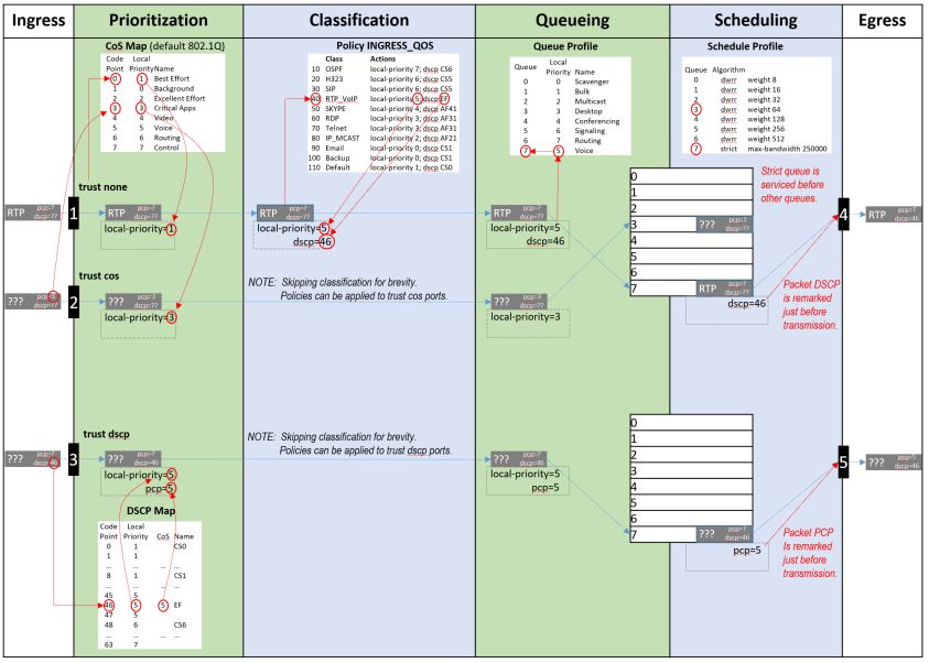
AOS-CX 10.07 Quality of Service Guide | (8360 Switch Series) 10The following diagram shows how different packets might traverse a switch. It also shows how QoS
configuration settings apply at each stage.
QoS trust
Traffic priorities for networks can be carried in VLAN tags, using the CoS Priority Code Point (PCP), or in IP
packet headers, using the Differentiated Services Code Point (DSCP). Whether these priorities affect how
traffic is serviced, depends on how QoS trust mode is configured on the switch. QoS trust mode specifies
how the switch assigns local priority values to ingress packets. Trust mode can be set globally for all
QoS overview | 11interfaces, or individually for each interface. By default, trust mode is set to none, meaning that any QoS
information in the packet (CoS or DSCP) is ignored, and local priority values are assigned from the CoS map
value for code point 0. An exception to this can be configured, allowing a QoS remark to be applied to DSCP
values when trust mode is none.
When trust mode is set to CoS or DSCP, the switch translates the QoS settings in VLAN tags (for CoS), or the
DS field in an IP header (for DSCP), to local priority values on the switch. Translation is controlled by the CoS
map or DSCP map tables.
For example:
Dynamic QoS trust mode
The device profile feature can dynamically set the QoS trust mode on an interface based on the LLDP
information exchanged with a link partner. The device profile's trust mode temporarily overrides the static
trust mode configured for an interface. The override remains in place as long as that link partner is
connected and its link state is up. Use command show interface IFNAME qos to view the current QoS trust
mode for an interface.
Port rate limiting
Port rate limiting helps control undesirable traffic. Its purpose is to allow enough broadcast, multicast, and
ICMP rate-limit traffic for the network to function properly, while preventing flooding and traffic storms.
A certain amount of each type of traffic is required for normal network operation. Broadcast packets may
include ARP and DHCP traffic, for instance. Video streams, and certain types of network protocol packets,
are multicasts. Unknown-unicast packets may be intended for devices whose addresses have temporarily
aged out of network-forwarding caches. Configuring rate limits can help provide the balance between
necessary and flooded traffic.
AOS-CX 10.07 Quality of Service Guide | (8360 Switch Series) 12Queue profiles
A queue profile defines the queues that are associated with an interface to control the transmission of
packets. Each profile supports up to eight queues, numbered 0 to 7. The larger the queue number, the
higher its priority during transmission scheduling. Packets are assigned to a queue based on their local
priority value (0 to 7). A queue profile must map all eight local priority values to whatever queues are being
used on the switch, and a schedule profile must specify the configuration for those same queues. A queue
without a local priority value assigned to it is not used to store packets.
The switch is automatically provisioned with an initial queue profile named factory-default which assigns
each local priority to the queue of the same number. To see the default queue profile, use the command
show qos queue-profile factory-default:
switch# show qos queue-profile factory-default
queue_num local_priorities name
--------- ---------------- ----
0 0 Scavenger_and_backup_data
1 1
2 2
3 3
4 4
5 5
6 6
7 7
More than one local priority value can be assigned to the same queue. For example,
Local
Queue
Priority
0 0
1 1
2 2
3 3
4 4
5 5
6 5
7 5
Commonly used commands for working with QoS queues are as follows:
n qos queue-profile: Creates an empty queue-profile and enters the profile configuration context.
n name queue: Assigns a descriptive name to a queue.
n map queue: Assigns a local-priority to a queue.
n apply qos queue-profile: Applies a queue-profile globally to all interfaces.
Schedule profiles
QoS overview | 13A schedule profile determines the order in which queues are selected for transmission, and the amount of
service available for each queue. A schedule profile must be configured on every interface at all times. A
schedule profile can be applied globally to all interfaces, or only to specific interfaces.
Three options are available:
n All queues use deficit weighted round robin queuing (DWRR)
n All queues use strict priority
n The highest priority queue uses strict priority, and all other queues use DWRR
NOTE: On the 8360 series switch all queues use guaranteed minimum bandwidth
A weighted schedule profile assigns relative servicing for each queue. The amount of service per weight is
relative to the underlying hardware implementation, and to the weights assigned to the other non-empty
queues. Strict scheduling can be used to service queues purely on the basis of highest priority first (at the
risk of starving lower-priority queues during high stress periods). A combination of strict and weighted
scheduling offers more service to the highest priority queue when needed, while preserving scheduling
between the remaining queues, thus decreasing the risk of starvation.
The switch is automatically provisioned with a schedule profile named factory-default, which assigns
DWRR to all queues with a weight of 1. Use the command show schedule-profile factory-default to
view the default schedule profile. (Do not use show running-configuration, as it only displays changes
from the initial settings.)
switch# show qos schedule-profile default
queue_num algorithm weight
--------- --------- ------
0 dwrr 1
1 dwrr 1
2 dwrr 1
3 dwrr 1
4 dwrr 1
5 dwrr 1
6 dwrr 1
7 dwrr 1
Egress queue shaping
Egress queue shaping limits the amount of traffic transmitted per strict output queue. The buffer associated
with each egress queue stores excess traffic to absorb bursts and smooths the output rate. For example, an
administrator might limit strict-priority queue traffic to prevent low-priority queue starvation in the event
that a device inappropriately sends too many higher-priority packets.
Egress queue shaping can be configured on an Ethernet port or on a link aggregation group (LAG). To
configure egress queue shaping, define a schedule profile with the strict priority algorithm assigned to each
queue.
Egress port shaping
Egress port shaping limits the amount of aggregate traffic transmitted through a port. To be effective, the
egress port-shaping rate must be less than the port's line rate. By default, the egress port-shaping rate is the
same as the line-rate of the port. Buffers associated with each port store excess traffic. When both egress
port-shaping and egress queue-shaping are configured on the same interface, the switch respects the
minimum of both configurations.
AOS-CX 10.07 Quality of Service Guide | (8360 Switch Series) 14Explicit Congestion Notification
Explicit Congestion Notification (ECN) provides a mechanism for two end-points to exchange end-to-end
notification of network congestion. ECN uses a 2-bit field in the IP header to indicate that the traffic load on
network equipment in the path between an ECN-capable sender and receiver is causing packets to be
buffered, as defined by IETF RFC 3168 (https://tools.ietf.org/html/rfc3168).
Threshold profiles
Threshold profiles configure individual queue utilization thresholds as triggers for taking action (i.e., ECN
marking) on a packet. A threshold profile is applied per-port and defines the threshold and action for each
queue. Omitting configuration for a queue in a threshold profile means that queue will not be configured
with a threshold value or action.
In an environment where responsive transport protocols are in use and congestion management features
are required to reduce latency, ECN can be configured on queues carrying delay-sensitive traffic. The result
is that queue utilization is actively managed, resulting in ECT packets being CE marked when queue
utilization reaches or exceeds a configured threshold.
Terms
Class
For networking, a set of packets sharing a common characteristic. For example, all IPv4 packets.
Code point
The name of a packet header field, or the value carried within a packet header field:
n Example 1: Priority code point (PCP) is the name of a field in the IEEE 802.1Q VLAN tag.
n Example 2: Differentiated services code point (DSCP) is the name of a field carried within the DS field
of an IP packet header.
Color
A metadata label associated with each packet within the switch. It has three values: green (0), yellow (1), or
red (2). When packets encounter congestion for a resource (queue), the switch uses packet color to
distinguish which packets must be dropped, and is mostly used for packets marked with Assured
Forwarding (AF) DSCP values.
Not supported in this release.
Class of service (CoS)
A 3-bit value used to mark packets with one of eight classes (levels of priority). It is carried within the
priority code point (PCP) field of the IEEE 802.1Q VLAN tag.
Differentiated services code point (DSCP)
A 6-bit value used to mark packets for different per-hop behavior as originally defined by IETF RFC 2474.
It is carried within the differentiated services (DS) field of the IPv4 or IPv6 header.
Local priority
A meta-data label associated with a packet within the switch which is used to classify packets for
different treatment (such as queue assignment). Eight local priorities are defined on the switch,
numbered from 0 to 7. A queue profile must map all eight local priorities to whatever queues are in use
on the switch, and a schedule profile must specify the configuration for these same queues.
Metadata
Information labels associated with each packet in the switch, separate from the packet headers and data.
These labels are used by the switch in its handling of the packet. For example: arrival port, egress port,
VLAN membership, and local priority.
Priority code point (PCP)
QoS overview | 15The name of a 3-bit field in the IEEE 802.1Q VLAN tag. It carries the CoS value to mark a packet with one
of eight classes (priority levels).
Quality of service (QoS)
General term used when describing or measuring performance. For networking, it means how different
classes of packets are treated when traversing a network or device.
Traffic class (TC)
General term for a set of packets sharing a common characteristic. It used to be the name of an 8-bit
field in the IPv6 header originally defined by IETF RFC 2460. This field name was changed to
differentiated services by IETF RFC 2474.
Type of service (ToS)
General term when there are different levels of treatment (fare class). It used to be the name of an 8-bit
field in the IPv4 header originally defined by IETF RFC 791. This field name was changed to differentiated
services by IETF RFC 2474.
AOS-CX 10.07 Quality of Service Guide | (8360 Switch Series) 16Chapter 3
QoS configuration
QoS configuration
Configuring QoS
Procedure
1. Optionally, add a rate limit for ingress traffic on one or more interfaces with the command rate-
limit.
2. If you do not want to use the default QoS queue profile to map local priority to queue, create one or
more custom queue profiles with the command qos queue-profile. For each queue in a custom
queue profile:
a. Assign a local priority value with the command map queue.
b. Optionally, define a descriptive name with the command name queue. All local priorities (0 to 7)
must be mapped to a queue, and the queues selected for use must be in contiguous order
starting at 0.
3. If you do not want to use the default QoS schedule profile to determine the order in which queues are
selected to transmit a packet, create one or more custom schedule profiles with the command qos
schedule-profile. For each queue in a custom schedule queue profile, define scheduling priority
with the commands strict queue and dwrr queue.
4. Optionally for strict queues, configure egress queue shaping to limit egress bandwidth on an interface
to a value that is less than its line rate. Use the max-bandwidth parameter of the strict queue
command.
5. Activate QoS settings with the command apply qos. This command lets you apply a queue profile
and schedule profile globally to all interfaces, or a schedule profile override to individual interfaces.
6. View QoS configuration settings with the provided show commands.
Examples
This example creates the following configuration:
Configuring expedited forwarding for VoIP traffic
Voice over IP (VoIP) traffic is delay and jitter sensitive. For optimum transmission of VoIP traffic, dwell time in
network devices must be kept to a minimum and all network devices in the data path must have identical
per-hop behaviors. To configure a dedicated queue on the switch to handle VoIP traffic with priority service
before all other queues, follow these steps.
Prerequisites
This scenario assumes that VoIP packets are uniquely identified using DiffServ code point 46, Expedited
Forwarding (EF).
Procedure
AOS-CX 10.07 Quality of Service Guide | (8360 Switch Series) 171. Map DSCP EF packets exclusively to local priority 5. The default DSCP map has eight code points (40
through 47), that are mapped to local priority 5. To reserve local priority 5 for VoIP traffic, the other
code points must be reassigned. In this scenario, local priority 6 is used for all reassignments,
including for code point 40, Call Signaling protocol (CS5).
switch(config)# qos dscp-map 40 local-priority 6 name CS5
switch(config)# qos dscp-map 41 local-priority 6
switch(config)# qos dscp-map 42 local-priority 6
switch(config)# qos dscp-map 43 local-priority 6
switch(config)# qos dscp-map 44 local-priority 6
switch(config)# qos dscp-map 45 local-priority 6
switch(config)# qos dscp-map 47 local-priority 6
2. Queue 7 is the highest priority queue, so for best throughput, create a queue profile that maps local
priority to queue 7.
switch(config)# qos queue-profile ef_priority
switch(config-queue)# name queue 7 Voice_Priority_Queue
switch(config-queue)# map queue 7 local-priority 5
switch(config-queue)# map queue 6 local-priority 7
switch(config-queue)# map queue 5 local-priority 6
switch(config-queue)# map queue 4 local-priority 4
switch(config-queue)# map queue 3 local-priority 3
switch(config-queue)# map queue 2 local-priority 2
switch(config-queue)# map queue 1 local-priority 1
switch(config-queue)# map queue 0 local-priority 0
3. Apply the profiles to all interfaces.
switch(config)# apply qos queue-profile ef_priority schedule-profile voip
4. Configure DSCP trust mode on all ports
switch(config)# qos trust dscp
Configuring rate limiting
This scenario illustrates how to use rate limiting to manage the traffic from various devices connected to a
switch. The physical topology of the network looks like this:
QoS configuration | 18A certain amount of broadcast traffic is necessary to maintain healthy network operation, particularly from
routers and across service boundaries. In this scenario, both the service cloud and the router connections
limit this traffic to 1 Gbps. The server has a smaller limit, as it does not require as much network protocol
traffic as the service cloud and router.
A multicast server needs to be able to stream multicast traffic to clients, so a multicast rate limit may not be
helpful. A computer, however, should not be generating large amounts of multicast traffic (it may be
receiving streams, but typically not sending them). In this example, the computer is configured with a
multicast rate limit to prevent malicious traffic from taking up network bandwidth.
Finally, while the service cloud and router may need to send traffic for unknown unicast addresses to
resolve address forwarding, the server and computer should send very little of this type of traffic. Rate
limiting unknown unicast traffic on those two devices enforces that.
Procedure
1. Configure broadcast and multicast rate limiting for the service cloud connection.
switch# config
switch(config)# interface 1/1/1
switch(config-if)# rate-limit broadcast 500 pps
switch(config-if)# rate-limit multicast 500 pps
switch(config-if)# exit
2. Configure broadcast rate limiting for the router connection.
switch(config-if)# interface 1/1/2
switch(config-if)# rate-limit broadcast 500 pps
switch(config-if)# exit
3. Configure broadcast rate limiting for the server connection.
switch(config-if)# interface 1/1/5
switch(config-if)# rate-limit broadcast 100 pps
switch(config-if)# exit
AOS-CX 10.07 Quality of Service Guide | (8360 Switch Series) 194. Configure broadcast, and multicast rate limiting for the computer connection.
switch(config-if)# interface 1/1/10
switch(config-if)# rate-limit broadcast 50 pps
switch(config-if)# rate-limit multicast 50 pps
Configuring egress queue shaping
This example shows how to apply egress queue shaping to an interface. First, a schedule profile is created
that has per-queue bandwidth limits set on all queues with strict as the scheduling algorithm. Next, this
profile is applied to an interface or LAG.
The following example creates a schedule profile named EQSExample, which services all seven queues using
strict priority. This profile configures queues 1, 4, and 7 with a bandwidth limit of 10 Gbps, 20 Gbps, and
30 Gbps respectively. The profile is then applied to interface 1/1/1.
switch(config)# qos schedule-profile EQSExample
switch(config-schedule)# strict queue 0
switch(config-schedule)# strict queue 1 max-bandwidth 10000000
switch(config-schedule)# strict queue 2
switch(config-schedule)# strict queue 3
switch(config-schedule)# strict queue 4 max-bandwidth 20000000
switch(config-schedule)# strict queue 5
switch(config-schedule)# strict queue 6
switch(config-schedule)# strict queue 7 max-bandwidth 30000000
switch(config-schedule)# exit
switch(config)# interface 1/1/1
switch(config-if)# apply qos schedule-profile EQSExample
Configuring egress port shaping
This example shows how to apply egress port shaping to an interface to limit the rate of egress traffic.
Egress port shaping is configured by specifying the desired bandwidth rate in kilobits per second (kbps). To
be effective, the egress rate must be less than the line rate of the egress interface. If the configured egress
rate exceeds the interface's line rate, then egress shaping has no effect.
The configured egress rate on a specific interface can be found by using the show interface and show
interface qos commands.
The following example configures an egress rate of 100 Mbps .
switch(config)# interface 1/1/1
switch(config-if)# qos shape 100000
In the next example, both egress port shaping and egress queue shaping are configured on the same
interface.
The example creates a schedule profile named EQSExample with strict priority for all seven queues. Queue 7
is configured with a bandwidth limit of 300 Mbps. The profile is then applied to interface 1/1/1 with egress
port shaping of 400 Mbps . As egress queue shaping and egress port shaping are both configured on port
1/1/1, egress queue shaping is subject to the lower port or queue shape rate. The effective bandwidth for
the traffic egressing on queue 7 will be 300 Mbps .
switch(config)# qos schedule-profile EQSExample
QoS configuration | 20switch(config-schedule)# strict queue 0
switch(config-schedule)# strict queue 1
switch(config-schedule)# strict queue 2
switch(config-schedule)# strict queue 3
switch(config-schedule)# strict queue 4
switch(config-schedule)# strict queue 5
switch(config-schedule)# strict queue 6
switch(config-schedule)# strict queue 7 max-bandwidth 300000
switch(config-schedule)# exit
switch(config)# interface 1/1/1
switch(config-if)# apply qos schedule-profile EQSExample
switch(config-if)# qos shape 400000
Supporting Ethernet 802.1D Class of Service
IEEE 802.1Q is the most current Ethernet standard for Class of Service (CoS). It superseded an earlier
standard, 802.1D, in 2005. IEEE 802.1Q slightly changed the ordering of the classes of service from its
predecessor IEEE 802.1D for CoS 2 and CoS 0:
CoS
CoS 802.1D
802.1Q
7 Network 7 Network Control
Control
6 6 Voice (switch(config)# exit
switch# show qos cos-map
code_point local_priority color name
---------- -------------- ------- ----
0 2 green Best_Effort
1 0 green Background
2 1 green Spare
3 3 green Critical_Applications
4 4 green Video
5 5 green Voice
6 6 green Internetwork_Control
7 7 green Network_Control
Monitoring queue operation
Use the show interface queues command to display the traffic transmitted per queue, and the number of
packets dropped due to the queue being full. For example:
switch# show interface 1/1/1 queues
Interface 1/1/1 is (Administratively down)
Admin state is down
State information: admin_down
Tx Packets Tx Bytes Tx Drops
Q0 100 8000 0
Q1 1234567 12345678908 5
Q2 0 0 0
Q3 0 0 0
Q4 0 0 0
Q5 0 0 0
Q6 0 0 0
Q7 0 0 0
n Tx Bytes: Total bytes transmitted. The byte count may include packet headers and internal metadata
that are removed before the packet is transmitted. Packet headers added when the packet is transmitted
may not be included.
n Tx Packets: Total packets transmitted.
n Tx Drops: The number of packets dropped by a queue before it was sent. When traffic cannot be
transmitted out of an egress interface, it may be buffered in memory if space is available. The more
servicing assigned to a queue by a schedule profile, the less likely traffic destined for that queue will back
up and potentially dropped.
QoS configuration | 22Chapter 4
QoS commands
QoS commands
apply qos
Syntax
apply qos [queue-profile ] schedule-profile
no apply qos schedule-profile
Description
Applies a queue profile and schedule profile globally to all Ethernet and LAG interfaces on the switch, or
applies a schedule profile to a specific interface. When applied globally, the specified schedule profile is
configured only on Ethernet interfaces and LAGs that do not already have their own schedule profile.
The same profile can be applied both globally and locally to an interface. This guarantees that an interface
always uses the specified profile, even if the global profile is changed.
The no form of this command removes the specified schedule profile from an interface and the interface
uses the global schedule profile. This is the only way to remove a schedule profile override from the
interface.
Interfaces may shut down briefly during reconfiguration.
Command context
config
config-if
config-lag-if
Parameters
queue-profile
Specifies the name of the queue profile to apply. Range: 1 to 64 alphanumeric characters, including
period (.), underscore (_), and hyphen (-). This parameter is not supported in the config-if context.
schedule-profile
Specifies the name of the schedule profile to apply. Range: 1 to 64 alphanumeric characters, including
period (.), underscore (_), and hyphen (-).
Authority
Administrators or local user group members with execution rights for this command.
Usage
n The switch must always have a globally-applied queue and schedule profile. To stop using a given profile,
apply a different profile.
n For a queue profile to be complete and ready to be applied, all eight local priorities must be mapped to a
queue.
AOS-CX 10.07 Quality of Service Guide | (8360 Switch Series) 23n For a schedule profile to be complete and ready to be applied, it must define all queues specified in the
queue profile. All queues must use the same algorithm, except for the highest numbered queue, which
can be strict.
n Both the queue profile and the schedule profile must specify the same number of queues.
n Schedule profiles can be modified while applied, but only in ways where a single command will not result
in the profile becoming invalid. For example, queue 7 can have the algorithm changed, and weighted
queues can have their weights changed.
If there are interfaces running with priority-based flow control (PFC) and a new queue profile to be applied
maps a local priority used by the PFC traffic to another queue, all PFC interfaces must be shutdown before
applying the new queue profile. If the new queue profile was applied before shutting down the PFC
interfaces, PFC traffic will still use the same queue from the previous profile until the interfaces are
shutdown then re-enabled.
If the number of queues was changed from the previous queue profile to the new one, any Ethernet or LAG
interfaces with locally applied schedule profiles will program the newly applied global schedule-profile. The
show running-config interface command will list the existing apply qos schedule-profile command with a
comment describing the actual profile applied:
Examples
Applying the QoS profile Q1 and the schedule profile S1 to all interfaces that do not have an applied
interface-specific schedule profile:
switch(config)# apply qos queue-profile Q1 schedule-profile S1
apply qos threshold-profile
Syntax
apply qos threshold-profile
no apply qos threshold-profile
Description
Applies a threshold profile globally to all Ethernet and LAG interfaces on the switch, or to a specific interface.
When applied globally, the specified threshold profile is configured only on Ethernet interfaces and LAGs
that do not already have their own schedule profile.
The same profile can be applied both globally and locally to an interface. This guarantees that an interface
always uses the specified threshold profile, even if the global profile is changed.
The no form of this command removes the specified threshold profile from an interface, and causes it to use
the global threshold profile. This is the only way to remove a threshold profile override from an interface. A
profile can only be deleted once it is no longer applied to any interface.
Command context
config
config-if
config-lag-if
Parameters
Specifies the name of the threshold profile to apply. Range: 1 to 64 alphanumeric characters, including
period (.), underscore (_), and hyphen (-).
QoS commands | 24Authority
Administrators or local user group members with execution rights for this command.
Example
Applying the threshold profile mythreshold to all interfaces that do not have an applied profile:
switch(config)# apply qos threshold-profile mythreshold
dwrr queue
Syntax
dwrr queue weight
no dwrr queue
Description
Assigns the deficit weighted round robin (DWRR) algorithm and its weight to a queue in a schedule profile.
DWRR allocates available bandwidth among all non-empty queues in relation to the queue weights.
The no form of this command removes the DWRR algorithm from a queue in a schedule profile.
Command context
config-schedule
Parameters
Specifies the queue number. Range: 0 to 7.
weight
Specifies the scheduling weight. Range: 1 to 1023.
Authority
Administrators or local user group members with execution rights for this command.
Examples
Assigning DWRR with a weight of 17 to queue 2 in the schedule profile myschedule:
switch(config)# qos schedule-profile myschedule
switch(config-schedule)# dwrr queue 2 weight 17
Deleting DWRR for queue 2 from the schedule profile myschedule:
switch(config)# qos schedule-profile myschedule
switch(config-schedule)# no dwrr queue 2
map queue
Syntax
map queue local-priority
no map queue [local-priority ]
AOS-CX 10.07 Quality of Service Guide | (8360 Switch Series) 25Description
Assigns a local priority to a queue in a queue profile. By default, the larger the queue number the higher its
priority. A queue without a local priority value assigned to it is not used to store packets. The same queue
can be assigned multiple local priorities.
The no form of this command removes the specified local priority from a specific queue. If no local priority
number is specified, then all local priorities are removed from the queue.
Command context
config-queue
Parameters
Specifies the queue number. Range: 0 to 7.
Specifies the local priority. Range: 0 to 7, where 0 is the lowest priority and 7 is the highest.
Authority
Administrators or local user group members with execution rights for this command.
Usage
For a queue profile to be complete and ready to be applied, all eight local priorities must be mapped to a
queue. Any local priority used by interface Priority-based Flow Control (PFC) must be the only local priority
mapped to its queue. In order for PFC pausing to work as intended, no other local priorities should be
mapped to that same queue. This queue mapping should be configured during initial switch provisioning
and only changed during maintenance periods where all ports are disabled.
The following commands illustrate a valid configuration, where every local priority value is assigned to a
queue:
map queue 0 local-priority 0
map queue 1 local-priority 1
map queue 1 local-priority 2
map queue 3 local-priority 3
map queue 4 local-priority 4
map queue 5 local-priority 5
map queue 5 local-priority 6
map queue 5 local-priority 7
The following commands illustrate an invalid configuration, because local priority 2 is not assigned to a
queue:
map queue 0 local-priority 0
map queue 1 local-priority 1
map queue 2 local-priority 3
map queue 3 local-priority 4
map queue 4 local-priority 5
map queue 5 local-priority 6
map queue 5 local-priority 7
Examples
Assigning priority 7 to queue 7 in profile myprofile:
QoS commands | 26switch(config)# qos queue-profile myprofile
switch(config-queue)# map queue 7 local-priority 7
Removing priority 7 from queue 7 in profile myprofile:
switch(config)# qos queue-profile myprofile
switch(config-queue)# no map queue 7 local-priority 7
min-bandwidth
Syntax
min-bandwidth queue percent
no min-bandwidth queue
Description
Assigns the Guaranteed Minimum Bandwidth (GMB) algorithm and a percentage of bandwidth to a queue.
GMB allocates available bandwidth among all non-empty queues in relation to their configured minimum
bandwidth. Non-empty queues are serviced first in strict order up to their minimum bandwidth. If there is
any remaining bandwidth, the scheduler will strictly service any remaining non-empty queues.
The no form of this command only clears the algorithm for a queue if GMB has been assigned.
Command context
config-schedule
Parameters
Specifies the queue number. Range: 0 to 7.
Specifies bandwidth percentage used for GMB scheduling. Range: 0 to 100.
Authority
Administrators or local user group members with execution rights for this command.
Examples
Assigning queue 0 of schedule profile S1 the GMB scheduling algorithm with minimum bandwidth of 5
percent:
switch(config)# qos schedule-profile S1
switch(config-schedule)# min-bandwidth queue 0 percent 5
Removing GMB from queue 0:
switch(config)# qos schedule-profile s1
switch(config-schedule)# no min-bandwidth queue 0
name queue
AOS-CX 10.07 Quality of Service Guide | (8360 Switch Series) 27Syntax
name queue
no name queue
Description
Assigns a description to a queue in a queue profile. This is for identification purposes and has no effect on
configuration.
The no form of this command removes the description associated with a queue.
Command context
config-queue
Parameters
Specifies the queue number. Range: 0 to 7.
Specifies a queue description for identification purposes. Range: 1 to 64 alphanumeric characters,
including period (.), underscore (_), and hyphen (-).
Authority
Administrators or local user group members with execution rights for this command.
Examples
Assigning the description priority-traffic to queue 7:
switch(config)# qos queue-profile myprofile
switch(config-queue)# name queue 7 priority-traffic
Removing the description from queue 7:
switch(config)# qos queue-profile myprofile
switch(config-queue)# no name queue 7
qos cos
Syntax
qos cos
no qos cos
Description
Configures a CoS PCP remark for an Ethernet or LAG interface. Packets that ingress on the interface are
remarked at egress using the configured CoS PCP value.
The remark only occurs when QoS trust mode on the interface is set to none.
If QoS trust mode is not set to none, then the remark is ignored, and the following commands will show the
CoS remark status as ignored (incompatible Port Access Trust configuration) or not applied'
(incompatible QoS global/port Trust configuration):
QoS commands | 28n show running-configuration
n show interface
n show interface qos
The no form of this command removes a CoS remark on an interface.
Command context
config-if
Parameters
Specifies an 802.1 VLAN priority CoS value. Range: 0 to 7.
Authority
Administrators or local user group members with execution rights for this command.
Examples
Configuring a CoS remark of 3 on interface 1/1/1:
switch(config)# interface 1/1/1
switch(config-if)# qos trust none
switch(config-if)# qos cos 3
Deleting a CoS remark of 3 on interface 1/1/1:
switch(config)# interface 1/1/1
switch(config-if)# no qos cos
qos cos-map
Syntax
qos cos-map local-priority [color ] [name
]
no qos cos-map
Description
Defines the local priority assigned to incoming packets for a specific 802.1 VLAN priority code point (CoS)
value. The CoS map values are used to mark incoming packets when QoS trust mode is set to cos. In trust
none mode, CoS map entry 0 is used to set the port default local priority and color.
To see the default CoS map settings, use the following command:
switch# show qos cos-map default
code_point local_priority color name
---------- -------------- ------- ----
0 1 green Best_Effort
1 0 green Background
2 2 green Excellent_Effort
3 3 green Critical_Applications
4 4 green Video
AOS-CX 10.07 Quality of Service Guide | (8360 Switch Series) 295 5 green Voice
6 6 green Internetwork_Control
7 7 green Network_Control
The no form of this command restores the assignments for a CoS map value to the default setting.
Command context
config
Parameters
Specifies an 802.1 VLAN priority CoS value. Range: 0 to 7. Default 0.
local-priority
Specifies a local priority value to associate with the CODE-POINT value. Range: 0 to 7. Default: 0.
color
Reserved for future use.
name
Specifies a description for the CoS setting. The name is for identification only, and has no effect on
queue configuration. Range: 1 to 64 alphanumeric characters, including period (.), underscore (_), and
hyphen (-).
Authority
Administrators or local user group members with execution rights for this command.
Usage
Any code point configured for use by interface Priority-based Flow Control (PFC) must be assigned a unique
local priority in the CoS map. No other code point can be assigned that same local priority. This should be
configured during initial switch provisioning and only changed during maintenance periods where all ports
are disabled.
Examples
Mapping CoS value 1 to a local priority of 2:
switch(config)# qos cos-map 1 local-priority 2
Mapping CoS value 1 to the default local priority value:
switch(config)# no qos cos-map 1
qos dscp
Syntax
qos dscp
no qos dscp
Description
Configures a differentiated services code point (DSCP) remark for an Ethernet or LAG interface. IPV4 and
IPV6 packets that ingress on the interface are remarked at egress using the configured DSCP value.
QoS commands | 30The remark only occurs when QoS trust mode on the interface is set to none. If a DSCP remark is configured
and then trust mode is subsequently set to cos or dscp, then the DSCP remark is ignored.
The following commands will show the remark status as ignored (incompatible Port Access Trust
configuration) or not applied (incompatible QoS global or port trust configuration):
n show running-configuration
n show interface
n show interface qos
The no form of this command removes a CoS remark on an interface.
Command context
config-if
config-lag-if
Parameters
Specifies an IP differentiated services code point value. Range: 0 to 63.
Authority
Administrators or local user group members with execution rights for this command.
Usage
Order of operation for arriving IPv4 or IPv6 packets:
1. Trust none is applied with initial local-priority and color metadata assigned from the CoS Map entry
index 0.
2. The local-priority value and the queue profile are then used to determine the queue for the packet.
3. The remark of the packet's DSCP metadata field is performed. When the packet is transmitted, its
IPv4 or IPv6 DS header is remarked with the DSCP metadata.
For arriving non-IP packets:
Trust none is applied with initial local-priority and color metadata assigned from the CoS Map entry index 0.
This selects the queue for packet scheduling. The PCP of any tagged non-IP packets is unchanged.
Examples
Configuring a DSCP remark of 43 on interface 1/1/1:
switch(config)# interface 1/1/1
switch(config-if)# qos trust none
switch(config-if)# qos dscp 43
Deleting a DSCP remark of 43 on interface 1/1/1:
switch(config)# interface 1/1/1
switch(config-if)# no dscp 43
qos dscp-map
AOS-CX 10.07 Quality of Service Guide | (8360 Switch Series) 31Syntax
qos dscp-map local-priority [color ] [cos ]
[name ]
no qos dscp-map
Description
Defines the local priority assigned to incoming packets for a specific IP differentiated services code point
(DSCP) value. The DSCP map values are used to prioritize incoming packets when QoS trust mode is set to
dscp.
The no form of this command restores the assignments for a code point to the default setting.
Use show qos dscp-map to view the current settings.To see the default DSCP map settings, use the
following command:
switch# show qos dscp-map default
code_point local_priority cos color name
---------- -------------- --- ------- ----
0 1 green CS0
1 1 green
2 1 green
3 1 green
4 1 green
5 1 green
...
45 5 green
46 5 green EF
47 5 green
48 6 green CS6
...
61 7 green
62 7 green
63 7 green
Command context
config
Parameters
Specifies an IP differentiated services code point. Range: 0 to 63. Default: 0.
local-priority
Specifies a local priority value to associate with the CODE-POINT value. Range: 0 to 7. Default: 0.
color
Reserved for future use
cos
Specifies an optional 802.1p VLAN Priority Code Point remark value. Range: 0 to 7. Default: No remark.
name
Specifies a description for the DSCP setting. The name is used for identification only, and has no effect
on queue configuration. Range: 1 to 64 alphanumeric characters, including period (.), underscore (_), and
hyphen (-).
Authority
Administrators or local user group members with execution rights for this command.
Examples
QoS commands | 32Setting code point 1 to a local priority of 2 and a CoS of 0:
switch(config)# qos dscp-map 1 local-priority 2 cos 0
Setting code point 1 to the default value:
switch(config)# no qos dscp-map 1
qos queue-profile
Syntax
qos queue-profile
no qos queue-profile
Description
Creates a new QoS queue profile and switches to the config-queue context for the profile. Or, if the
specified QoS queue profile exists, this command switches to the config-queue context for the profile. A
queue profile maps queues to local-priority values. Each profile has one to eight queues numbered 0 to 7.
The larger the queue number, the higher its priority during transmission scheduling.
A queue profile named factory-default is defined by default and is automatically applied to all interfaces. It
cannot be edited or deleted. Use the command show qos queue-profile factory-default to view this
profile. Do not use show running-configuration, as it will only display changes from the initial values. Use
show qos queue-profile [NAME] to view the status of all queue profiles or the settings of the named
profile.
The no form of this command removes the specified QoS queue profile. Only profiles that are not currently
applied can be removed.
Command context
config
Parameters
Specifies the name of the QoS queue profile to create or configure. Range: 1 to 64 alphanumeric
characters, including period (.), underscore (_), and hyphen (-).
Authority
Administrators or local user group members with execution rights for this command.
Examples
Creating the profile myprofile:
switch(config)# qos queue-profile myprofile
switch(config-queue)#
Deleting the profile myprofile:
switch(config)# no qos queue-profile myprofile
AOS-CX 10.07 Quality of Service Guide | (8360 Switch Series) 33qos schedule-profile
Syntax
qos schedule-profile
no qos schedule-profile
Description
Creates a QoS schedule profile and switches to the config-schedule context for the profile. If the specified
schedule profile exists, this command switches to the config-schedule context for the profile. The
schedule profile determines the order in which queues are selected to transmit a packet, and the amount of
service defined for each queue.
Command context
config
Parameters
Specifies the name of the QoS schedule profile to create or configure. Range: 1 to 64 alphanumeric
characters, including period (.), underscore (_), and hyphen (-).
Authority
Administrators or local user group members with execution rights for this command.
Usage
Queues in a schedule profile are numbered consecutively starting from zero. Queue zero is the lowest
priority queue. The larger the queue number, the higher priority the queue has in scheduling algorithms.
A profile named factory-default is defined by default and applied to all interfaces. It cannot be edited or
deleted. To see its settings, use the command:
switch# show qos schedule-profile factory-default
queue_num algorithm weight
--------- --------- ------
0 dwrr 1
1 dwrr 1
2 dwrr 1
3 dwrr 1
4 dwrr 1
5 dwrr 1
6 dwrr 1
7 dwrr 1
A profile named strict is predefined and cannot be edited or deleted. The strict profile services all queues of
the queue profile to which it is applied, using the strict priority algorithm.
A schedule profile must be defined on all interfaces at all times.
There are two permitted configurations for a schedule profile:
1. All queues use the same scheduling algorithm (for example, DWRR).
2. The highest queue number uses strict priority, and all remaining (lower) queues use the same
algorithm (for example, DWRR). This supports priority scheduling behavior necessary for the IEFT RFC
3246 Expedited Forwarding specification (https://tools.ietf.org/html/rfc3246).
QoS commands | 34Only limited changes can be made to an applied schedule profile:
n The weight of a dwrr queue.
n The bandwidth of a strict queue.
n The algorithm of the highest numbered queue can be swapped between dwrr and strict, and vice versa.
Applicable to REST: Any other changes will result in an unusable schedule profile, and the switch will revert to
the factory-default profile until the profile is corrected.
The no form of this command removes the specified QoS schedule profile when it is not applied. Only
profiles that are not currently applied to an interface can be removed.
Examples
Creating the schedule profile myschedule:
switch(config)# qos schedule-profile myschedule
switch(config-schedule)#
Deleting the schedule profile myschedule:
switch(config)# no qos schedule-profile myschedule
qos shape
Syntax
qos shape
no qos shape
Description
Limits the egress bandwidth on an interface to a value that is lower than its line rate.
The no form of this command removes shaping from an interface.
Command context
config-if
Parameters
Specifies the maximum traffic rate in kbps. Range 64 to 100000000.
Authority
Administrators or local user group members with execution rights for this command.
Usage
When the traffic rate destined for the port exceeds the configured egress bandwidth, the switch will buffer
the excess up to the limit of the queues. Rates larger than the interface line rate will have no effect. When
set on a LAG, each member Ethernet port independently shapes its egress bandwidth to the specified rate.
Examples
Configuring an egress port shaping rate of 400 Mbps on interface 1/1/1:
AOS-CX 10.07 Quality of Service Guide | (8360 Switch Series) 35switch(config)# interface 1/1/1
switch(config-if)# qos shape 400000
Deleting egress port shaping on interface 1/1/1:
switch(config)# interface 1/1/1
switch(config-if)# no qos shape
qos threshold-profile
Syntax
qos threshold-profile
no qos threshold-profile
Description
Creates a QoS threshold profile and switches to the config-threshold context for the profile. If the
specified threshold profile exists, this command switches to the config-threshold context for the existing
profile. The threshold profile determines the action to take when a threshold is exceeded for each queue.
A threshold profile is composed of up to 7 queues, numbered from 0-6. Each queue defines the action to
take when buffer utilization exceeds a specific threshold.
Configure queues with the command queue.
The no form of this command removes the specified QoS threshold profile. Only profiles that are not
currently applied to an interface can be removed.
Command context
config
Parameters
Specifies the name of the QoS threshold profile to create or configure. Range: 1 to 64 alphanumeric
characters, including period (.), underscore (_), and hyphen (-).
Authority
Administrators or local user group members with execution rights for this command.
Usage
Queues in a threshold profile can be any valid queue number, although it is also valid to create a threshold
profile with no queues specified. Queue zero is the minimum allowed queue number. The maximum
allowed queue number may vary by product. For products supporting eight queues, the largest queue
number is seven. If an applied threshold profile specifies configuration of a queue number that is not in use
based on the configured queue profile, the threshold configuration of that unused queue is ignored.
Examples
Creating the threshold profile mythreshold :
QoS commands | 36You can also read