Specification for Road Safety Hardware Systems - APPENDIX A: PERMANENT ROAD SAFETY BARRIER SYSTEMS - Timber Faced Guardrail
←
→
Page content transcription
If your browser does not render page correctly, please read the page content below
NZTA M23A 2017   |   2

Specification for Road Safety
Hardware Systems
APPENDIX A: PERMANENT ROAD SAFETY BARRIER SYSTEMS

                                                       October 2017

                                       Prepared for NZTA by Parallaxx Ltd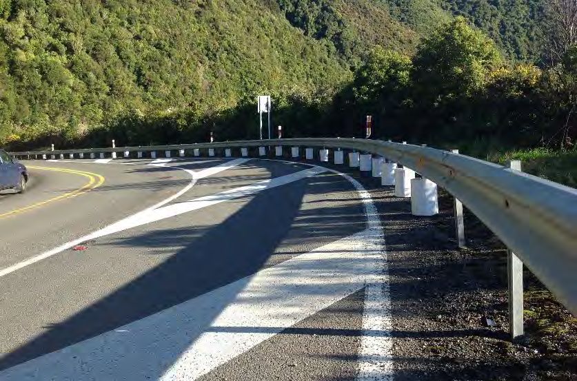
NZTA M23A 2017   |    1

INTRODUCTION AND REFERENCES
This hardware summary manual has been prepared to assist
organisations and individuals who interact with Road Safety Barrier
Systems and Devices. The technical details within this manual                               If you have further queries, call our contact
                                                                                            centre on 0800 699 000 or write to us:
have been extracted from the respective product, installation and
                                                                                            NZ Transport Agency
technical manuals of each system/device.                                                    Private Bag 6995
                                                                                            Wellington 6141
For more detailed information, refer to the individual manuals
                                                                                            This publication is also available on
for each product or contact the System Supplier.                                            NZ Transport Agency’s website at
                                                                                            www.nzta.govt.nz
The information, commentary and details provided in this manual
are collected from a variety of reliable sources however the System
Owner/Supplier, and formally issued and endorsed material must
still be used as reference material for products. Do not utilise a
system/device listed in this manual without first consulting the
System Owner/System Supplier and obtaining the correct and
most recent documentation for the product.

This manual is prepared with the intention of providing basic
outline detail on all permanent road safety barrier systems
accepted for use by NZTA.systems for use by NZTA.

The NZTA is part of, and contributes to, the Safer Journeys programme.
Safer Journeys is the government’s strategy to guide improvements in road safety over the period 2010–2020. The strategy’s vision is a safe
road system increasingly free of death and serious injury. It is a co-ordinated effort across partner agencies to improve each aspect of road
safety – better behaviors, a safer road environment, safer speeds and higher vehicle standards.
For more information visit www.transport.govt.nz/saferjourneys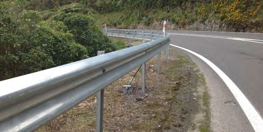
NZTA M23A 2017   |       2

CONTENTS

GLOSSARY                                                                              4
NON-PROPRIETARY ROADSIDE & MEDIAN BARRIER SYSTEMS                                     6
SEMI-RIGID ROADSIDE & MEDIAN BARRIERS                                                 6
STRONG-POST TIMBER W-BEAM GUARDRAIL (SGR04B)                                           6
STEEL-POST THRIE-BEAM GUARDRAIL (MODIFIED BLOCKOUT) (SGR09B)                              7
STRONG-POST W-BEAM DOUBLE-SIDED GUARDRAIL (SGM04B)                                     8
STEEL-POST THRIE-BEAM DOUBLE-SIDED GUARDRAIL (MODIFIED BLOCKOUT) (SGM09B)              9
RIGID ROADSIDE & MEDIAN BARRIERS                                                      10
F-SHAPE CONCRETE BARRIER                                                              10
VGAN 300 ALUMINIUM BRIDGE BARRIER                                                     11
PROPIETARY ROADSIDE & MEDIAN BARRIER SYSTEMS                                          12
FLEXIBLE BARRIER SYSTEMS                                                              12
ARMORWIRE WRSB - INCLUDING ARMORWIRE TERMINAL END (A.T.E)                             12
BRIFEN 4 CABLE WIRE ROPE SAFETY BARRIER (WRSB)                                        14
SAFENCE SLOPE WRSB                                                                    15
SAFENCE TL4 WRSB                                                                      16
PROPIETARY ROADSIDE & MEDIAN BARRIER SYSTEMS                                          17
CONTINUOUS MOTORCYCLIST PROTECTION SYSTEMS                                            17
INGAL MOTORCYCLIST PROTECTION RAIL                                                    17
DISCONTINUOUS MOTORCYCLIST PROTECTION SYSTEMS                                         18
IMPACTPROTECT MOTORCYCLE PROTECTION SYSTEM                                            18
PROPIETARY ROADSIDE & MEDIAN BARRIER SYSTEMS                                          19
SEMI-RIGID SYSTEMS                                                                    19
EZY-GUARD 4 W-BEAM GUARDRAIL                                                          19
NU-GUARD® 31 W-BEAM GUARDRAIL                                                         20
EZY-GUARD HC THRIE-BEAM GUARDRAIL                                                     21
TIMBER FACED GUARDRAIL G4M AND G2M                                                    23
TIMBER FACED GUARDRAIL GRP                                                            24
LOGRAIL T18 4M/4MS2                                                                   25
W-BEAM END TERMINALS                                                                  26
ET2000 PLUS END TERMINAL SYSTEM                                                       26
FLEAT 350 & SKT 350 END TERMINALS                                                     27
SOFTSTOP END TERMINAL SYSTEM                                                          28
X-350 END TERMINAL SYSTEM                                                             29
TRAILING TERMINAL                                                                     30
BURIED IN BACKSLOPE ANCHOR                                                            31
NZTA M23A 2017   |    3

CRASH CUSHIONS                                                    32
PERMANENT SYSTEMS                                                 32
CAT 350 CRASH CUSHION                                             32
QUAD-GUARD CRASH CUSHION                                          33
SCI-100 SMART CUSHION                                             33
UNIVERSAL TAU- II CRASH CUSHION SYSTEM                            35
TRACC CRASH ATTENUATION CUSHION                                   36
X-TENUATOR CRASH CUSHION                                          37
RAPTOR CRASH CUSHION                                              38
MEDIAN GATE SYSTEMS                                               39
ARMORGUARD GATE STEEL MEDIAN GATE SYSTEM                          39
BARRIERGUARD 800 GATE STEEL MEDIAN GATE SYSTEM                    40
IRONMAN MEDIAN GATE STEEL MEDIAN GATE SYSTEM                      42
TRANSITIONS                                                       43
PERMANENT USE SYSTEMS                                             43
NZTA SEMI-RIGID TO RIGID THRIE-BEAM TRANSITION                    43
WIRE ROPE SAFETY BARRIER (WRSB) TRANSITIONS                       44
CURVED BARRIER INSTALLATIONS                                      46
CURVED W-BEAM GUARDRAIL TERMINAL (RSB2, RSB2A)                    46
NZTA M23A 2017   |   4

GLOSSARY
(Refer also to AS/NZS 3845 Part 1 2015 and Part 2 2017)

 Anchorage                       A barrier system may be anchored to the ground to limit deflection.

 Bi-directional application      Two-way traffic. E.g. Barrier hardware that can be hit by both adjacent and opposing traffic.

 Chevron                         Retro-reflective chevron signs attached to the barrier units to guide drivers along a temporary barrier
                                 system (CoPTTM B12).

 Clear Zone                      A clear zone is the area adjacent to the traffic lane that should be kept free from hazards that could be
                                 impacted by errant vehicles.

 CoPTTM                          NZTA Code of Practice for Temporary Traffic Management.

 Crashworthy                     A feature that has been proven acceptable for use under specified conditions either through crash testing
                                 or in-service performance.

 Crossfall                       The transverse sloping of the road surface toward the shoulder or gutter.

 Deflection                      The horizontal displacement of the barrier when impacted.

 End Terminal                    A crashworthy end treatment must be provided when the end of a barrier is exposed to head-on impacts.

 Energy Absorbing Unit           The individual units in a crash cushion that absorb impact energy.

 FHWA                            USA Federal Highways Administration.

 Flare Rate                      The curvature applied near the end of a road safety barrier installation. Expressed as the ratio of the
                                 longitudinal distance to the transverse offset, by which a road safety barrier flares away from the road.

 Flexible Barrier                Barrier systems which dissipate crash impact energy largely by deflection of the barrier system. Lower
                                 impact forces are imposed on the vehicle and occupants.

 F-Shape Barrier                 Concrete barrier of the current accepted F shape cross-section.

 Gating                          A road safety barrier terminal designed to allow an impacting vehicle to pass through the device, when
                                 impacted at an angle, upstream from the point of redirection.

 Impact angle                    For a longitudinal barrier, it is the angle between the face of the barrier and the vehicle’s impact direction.

 Length of need                  The required length of barrier system that is re-directive, to shield the hazard.

 MASH                            Manual for Assessing Safety Hardware (MASH) is a Manual for Assessing Highway Safety Features.

 NCHRP-350                       National Co-operative Highway Research Program (report) 350.

 New Jersey Barrier              Generally a concrete barrier of the New Jersey Barrier profile. Superseded by the F-shape.

 Pinning                         Either connecting adjacent transportable barrier sections, or fastening barrier sections to the pavement
                                 of ground.

 Point of Redirection            That point on a barrier system downstream of which will be redirective. Previously referred to as
                                 ‘point of need’

 Proprietary                     A road safety barrier system that is the subject of patent or other intellectual property rights.

 Redirective                     The ability of a barrier system to re-direct an impacting vehicle without barrier pocketing or rupture.

 Ribbon Strength                 The longitudinal strength of a barrier system to provide crash energy containment and redirection.

 Rigid Barrier                   Barrier system that has no deflection under impact. Higher impact energy transmitted to vehicle
                                 and occupants.

 Semi-Rigid Barrier              Barrier system deflects during re-direction. Impact energy to vehicle and occupants is less than for a rigid
                                 system but greater than a flexible system.

 Shy Line                        The distance from the edge of the travelled way outside of which the start of a roadside object (e.g.
                                 barrier) will not cause a driver to change their vehicles lateral placement or speed.

 Sight/ Anti-Gawk Screens        Screens to shield visual distractions from passing drivers.

 Slope                           The relative steepness of the terrain expressed as a ratio or percentage.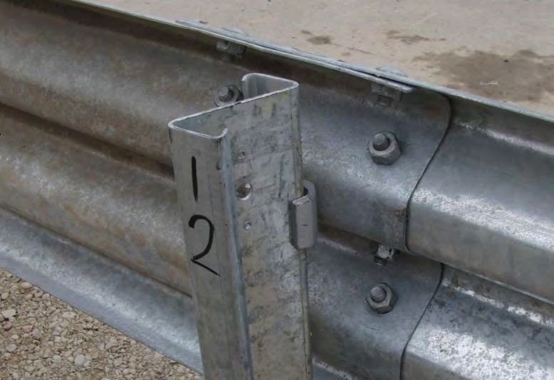
NZTA M23A 2017   |    5

Test Level (TL)               A set of prescribed test conditions, defined in terms of vehicular mass, impact speed and angle that defines
                              the crash energy.

Uni-directional application   One-way traffic. E.g. Barrier hardware that cannot be hit by opposing traffic.

Vaulting                      Abrupt upward movement of an impacting vehicle.

Wear and tear                 Damage that naturally and inevitably occurs as a result of normal use or aging.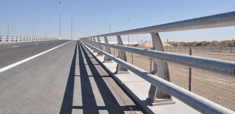
NZTA M23A 2017 | 6
NON-PROPRIETARY ROADSIDE & MEDIAN BARRIER SYSTEMS
SEMI-RIGID ROADSIDE & MEDIAN BARRIERS
STRONG-POST W-BEAM GUARDRAIL (SGR04B)
SUMMARY
SUPPLIER: Open source - no specific supplier
TEST LEVEL / CONDITIONS: NCHRP-350 TL-3
FOR USE WITH Attaches to compatible transition barriers (generally transitioning into a wall or Thrie-Beam)
STATUS Legacy System, repair use only, not for new State Highway installations
Strong Post Timber W-Beam guardrail is a common type of longitudinal barrier in use along local roads and State Highways. It is a public domain
(non-proprietary) system.
The wood or plastic blockouts reduce or minimise a vehicle snagging on the posts upon impact. In addition, a blockout may be used to increase
the offset of guardrail with an obstacle such as a curb. The posts’ primary purpose is to maintain the height of the guardrail during the initial stages
of post deflection.
Strong Post Timber W-Beam guardrail is a legacy system and may not be installed on new State Highway projects. Existing installations may be
repaired/maintained until replacement with a higher performing barrier system is viable or necessary.
TECHNICAL INFORMATION
DIMENSIONS 1905mm post spacing
660mm < Height < 762mm
MINIMUM LENGTH Unit length: 3810 mm
DEFLECTION 800mm
OTHER RESTRICTIONS / W-Beam guardrails should be anchored and terminated using a suitable end treatment
CONSIDERATIONS 2 x 16d nails per blockout to prevent rotation
Barrier post offset to hinge point =1m (600mm minimum)
Legacy system, not for new State Highway installations
COMMON FAULTS / OTHER CONSIDERATIONS
•• W-Beam guardrail element may be considered serviceable after damage to a single rib, but non serviceable if there is damage to 2 ribs
within 2m.
•• Limited ability of the system to contain and redirect modern vehicles that have a higher centre of gravity along with the increased weight
of those vehicles.
FURTHER READING / REFERENCES
•• Refer to AASHTO 2-Space W-Beam Guardrail (RWM02a-b) for details of W-Beam element.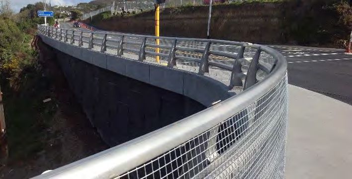
NZTA M23A 2017 | 7
STEEL POST THRIE-BEAM GUARDRAIL (MODIFIED BLOCKOUT) (SGR09B)
SUMMARY
SUPPLIER: Open source - no specific supplier
TEST LEVEL / CONDITIONS: NCHRP-350 TL4
FOR USE WITH Any common W-Beam terminal can be used in conjunction with an RSB-5 transition to provide a
crashworthy terminal and anchorage.
STATUS Accepted
“Modified Thrie-Beam” (SGR09b) is a modified version of the standard SGR09c Thrie-Beam with modified (notched) blockouts. It is a public
domain (non-proprietary) system.
The SGR09b uses steel I-section posts with steel I-section blockouts and is a Test Level 4 barrier.
Strong post Thrie-Beam guard rails should be used in locations where there is at least 600 mm of available deflection space.
TECHNICAL INFORMATION
DIMENSIONS 2000mm post spacing
4000mm rail length
Height > 838mm
MINIMUM LENGTH Unit length: 3810 mm
DEFLECTION 900mm (NCHRP-350 TL4)
OTHER RESTRICTIONS / High level of performance especially for large vehicles
CONSIDERATIONS Barrier post offset to hinge point =1m (600mm minimum)
COMMON FAULTS / OTHER CONSIDERATIONS
•• Thrie-Beam guardrail element may be considered serviceable after damage to a single rib, but non serviceable if there is damage to 2
ribs within 2m.
•• Modified Thrie-Beam on baseplate mounted posts is the minimum system acceptable for use on State Highway structures. Refer M23
Appendix B for details.
•• Modified Thrie-Beam blockouts must be compliant with the AASHTO PWB03 detail and fabricated from either:
- rolled steel section conforming to either W360x32.9 or M360x25.6 section profiles defined in AASHTO M160M, or
- welded steel plate to the same dimensions and strengths (continuous fillet welds with minimum 6mm leg length,
Cat SP to AS/NZS1554.1)
•• The “notch” must be correctly formed with no rib or residual web material remaining behind the traffic face flange to ensure the system
operates as tested.
FURTHER READING / REFERENCES
•• Refer to AASHTO Strong Post Thrie-Beam Guardrail (SGR09b) for details of Thrie-Beam system.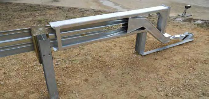
NZTA M23A 2017 | 8
STRONGPOST W-BEAM DOUBLE-SIDED GUARDRAIL (SGM04B)
SUMMARY
SUPPLIER: Open source - no specific supplier
TEST LEVEL / CONDITIONS: TL3. NCHRP-350 TL-3
FOR USE WITH W-Beam barriers should be anchored and terminated using a suitable end treatment.
STATUS Legacy System, repair use only, not for new State Highway installations
Strong Post Timber W-Beam median barriers were generally used in locations where a maximum dynamic deflection of 600 mm or less was
acceptable. It is a public domain (non-proprietary) system.
The SGM04b uses timber posts with wooden blockouts and was a Test Level 3 barrier.
Strong Post Timber W-Beam median barrier is a legacy system and may not be installed on new State Highway projects. Existing installations
may be repaired/maintained until replacement with a higher performing barrier system is viable or necessary.
TECHNICAL INFORMATION
DIMENSIONS 1905mm post spacing
660mm < Height < 762mm
MINIMUM LENGTH Unit length: 3810 mm
DEFLECTION 600mm to 1200mm
OTHER RESTRICTIONS / W-Beam barriers should be anchored and terminated using a suitable end treatment.
CONSIDERATIONS 2 x 16d nails used on each side to prevent block rotation.
COMMON FAULTS / OTHER CONSIDERATIONS
•• W-Beam guardrail element may be considered serviceable after damage to a single rib, but non serviceable if there is damage to 2 ribs
within 2m.
•• Legacy system, not for new State Highway installations.
FURTHER READING / REFERENCES
•• Refer to AASHTO 2-Space W-Beam Guardrail (RWM02a-b) for details of W-Beam element.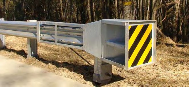
NZTA M23A 2017 | 9
STEEL POST THRIE-BEAM DOUBLE-SIDED GUARDRAIL (MODIFIED BLOCKOUT)
(SGM09B)
SUMMARY
SUPPLIER: Open source - no specific supplier
TEST LEVEL / CONDITIONS: NCHRP-350 TL-4
FOR USE WITH Any common W-Beam terminal can be used in conjunction with an RSB-5 transition to provide a
crashworthy terminal and anchorage.
STATUS Accepted
The SGM09b is a modified version of the SGM09a and SGM09c Thrie-Beams and is a Test Level 4 barrier.
The SGM09b uses steel posts and a modified Thrie-Beam blockout instead of timber post blockouts.
Strong-post Thrieb-Beam median barriers should be used in locations where a maximum dynamic deflection of 500 mm is acceptable.
TECHNICAL INFORMATION
DIMENSIONS 2000mm post spacing
4000mm rail length
Height > 838mm
MINIMUM LENGTH Unit length: 3810 mm
DEFLECTION 300mm to 900mm
OTHER RESTRICTIONS / Thrie-Beam barriers can be more effective than W-beam barriers in collisions with larger vehicles.
CONSIDERATIONS This barrier system must be properly anchored and terminated.
COMMON FAULTS / OTHER CONSIDERATIONS
•• Thrie-Beam guardrail element may be considered serviceable after damage to a single rib, but non serviceable if there is damage to 2 ribs
within 2m.
•• Modified Thrie-Beam on baseplate mounted posts is the minimum system acceptable for use on State Highway structures. Refer M23
Appendix B for details.
•• Modified Thrie-Beam blockouts must be compliant with the AASHTO PWB03 detail and fabricated from either:
- rolled steel section conforming to either W360x32.9 or M360x25.6 section profiles defined in AASHTO M160M, or
- welded steel plate to the same dimensions and strengths (continuous fillet welds with minimum 6mm leg length, Cat SP to
AS/NZS1554.1)
•• The “notch” must be correctly formed with no rib or residual web material remaining behind the traffic face flange to ensure the system
operates as tested.
FURTHER READING / REFERENCES
•• Refer to AASHTO Strong Post Thrie-Beam Guardrail (SGR09b) for details of Thrie-Beam systemNZTA M23A 2017 | 10
RIGID ROADSIDE & MEDIAN BARRIERS
F-SHAPE CONCRETE BARRIER
SUMMARY
SUPPLIER: Open source - no specific supplier
TEST LEVEL / CONDITIONS: TL4 – minimum height 915mm
TL5 – minimum height 1070mm
FOR USE WITH A 3m long 250mm deep reinforced anchor footing must be provided at both ends, and every 60m, to
properly secure the barrier.
ACCEPTANCE NOTICE Accepted
The barrier may be cast-in-place, slip formed or pre cast. Cast-in-place and slip formed barrier will normally be a continuous pour without
transverse contraction joints. Cast-in-place segments less than 12m in length must be joined to adjacent sections by at least three 25mm diameter
steel dowels, or an equivalent joining method approved by the NZ Transport Agency.
TECHNICAL INFORMATION
DIMENSIONS As shown above (refer also AASHTO SGM10a-b)
MINIMUM LENGTH 6m barrier length is used commonly for pre-cast permanent units.
Maximum barrier length between anchor footings: 60m
DEFLECTION Rigid system – designed to facilitate 0.0m deflection
OTHER RESTRICTIONS / Specification for slip formed variant provided as Appendix D of this Specification
CONSIDERATIONS Reinforcing steel shall be grade 500E or 500N conforming to AS/NZS 4671 and increased from 15
mm to 16 mm.
Concrete used in the construction shall comply with the requirements of NZS 3109 and shall be
manufactured in accordance with NZS 3104.
The minimum concrete cover depth is 50mm.
The 28 day compressive strength and concrete binder type shall be in accordance with the
durability requirements of NZS 3101 for the relevant exposure classification but in all cases shall be
a minimum of 30 MPa.
Open joints should be provided at least every 60m, although 6 m is more common.
COMMON FAULTS / OTHER CONSIDERATIONS
• F-Shape barriers can be used as either median barriers or roadside barriers, but the correct barrier must be used for the
correct situation.
• Other common methods of supporting the barrier include setting the barrier in a continuous keyed foundation or dowelling the barrier
to a foundation.
• “Pin and loop” or other temporary concrete barrier joint configurations are not accepted for use as permanent barriers.NZTA M23A 2017 | 11
VGAN 300 ALUMINIUM BRIDGE BARRIER
SUMMARY
SUPPLIER: CSP Pacific (http://www.csppacific.co.nz/)
TEST LEVEL / CONDITIONS: TL3 and TL4. NCHRP-350 TL-3 and TL-4
PRODUCT MANUAL: Click for product manual download
FOR USE WITH Transition available to TL-4 Thrie-Beam and then on to standard 12g W-Beam guardrail systems
ACCEPTANCE NOTICE
The VGAN 300 Aluminium Bridge Barrier system is a permanent aluminium barrier system comprising cast aluminium posts carrying 3 main
extruded aluminium barrier rails. The posts are at nominal 2.4m centres and the nominal system height is 1.1m. The VGAN 300 Aluminium Bridge
Barrier system is classed as a rigid performance level 4 barrier system in terms of the NZ Transport Agency Bridge Manual.
TECHNICAL INFORMATION
DIMENSIONS Post Spacing: 2.4m centres
System Height: 1.1m
Two lower pedestrian rails: 152mm x 98mm
Top pedestrian rail: 114mm x 72mm
Rail lengths: 9.735m
Minimum plinth width: 450mm
WEIGHT 28.10kg per metre
MINIMUM LENGTH Minimum length of the bridge parapet is as follows:
15m for TL-3
30m for TL-4
GRADE OR PLACEMENT Cannot be used where pedestrian protection has to meet the NZ Building Code.
RESTRICTIONS
DEFLECTION Maximum system deflection is 300mm at NCHRP-350 TL-4.
OTHER RESTRICTIONS / Mesh infill option available.
CONSIDERATIONS The minimum horizontal curvature without pre-curving of main rails is 150m. Smaller radii can be
accommodated with pre-curving.
Posts can accommodate vertical alignments of up to ± 2.5º. However, when the vertical alignment
results in a longitudinal fall in excess of 2.5° the posts should be fixed square to the concrete plinth
transversely and perpendicular to the concrete longitudinally.
COMMON FAULTS / OTHER CONSIDERATIONS
- The manufacturer’s connection detail in conjunction with the NZ Transport Agency standard transition detail (RSB-5) must be used to
connect the VGAN 300 Aluminium Bridge Barrier system to a semi-rigid road safety barrier on the structure approach.
- Where a rigid road safety barrier is installed on the approach, the manufacturer’s detail must be used. Where parapet meshing is
required to meet Building Code and or road controlling authority requirements, the manufacturer’s detail must be used or an alternative
fixing agreed.
FURTHER READING / REFERENCESNZTA M23A 2017 | 12
PROPRIETARY ROADSIDE & MEDIAN BARRIER SYSTEMS
FLEXIBLE BARRIER SYSTEMS
ARMORWIRE WRSB - INCLUDING ARMORWIRE TERMINAL END (A.T.E)
SUMMARY
SUPPLIER: CSP Pacific (http://www.csppacific.co.nz/)
TEST LEVEL / CONDITIONS: NCHRP-350 TL-4
NCHRP-350 TL-3 (Local road installation only)
PRODUCT MANUAL: Click for product manual download
FOR USE WITH Armorwire Terminal End (A.T.E)
STATUS Accepted
Armorwire TL-4 is a tensioned wire rope safety barrier (WRSB) system comprising oval shaped steel posts supporting 4 cables and uses the
Armorwire Terminal End (A.T.E) anchor. The system has been successfully tested to both NCHRP 350 Test Level 3 and Test Level 4.
TECHNICAL INFORMATION
DIMENSIONS Cable heights, TL-4: 530mm, 650mm and 770mm and 790mm. (± 25mm)
Cable – 19mm 3 x 7 strand, pre-stretched by 35%
Post spacing: 3m.
Std concrete post footing: 300mm diameter by 750mm deep in compacted road base.
MINIMUM LENGTH Minimum barrier length is 114m and represents the distance between the upstream and downstream Length
of Need of the terminal ends. i.e. excludes the 8m of Armorwire Terminal End (A.T.E) cable at either end.
GRADE OR PLACEMENT A maximum slope of 10H:1V is preferable. On slopes greater than this, advice should be followed from
RESTRICTIONS the Road Controlling Authority’s guidelines.
Offset to hinge point =1m (600mm minimum)
DEFLECTION 1.54m (based on NCHRP-350 TL-3 test)
OTHER RESTRICTIONS / Used in both median and roadside situations in either orientation as long as the slot arrangement
CONSIDERATIONS is consistent.
The maximum flare is 30:1 over the entire length of the terminal end.
The 4 line posts between the terminal end ‘trigger’ post and the Armorwire cable barrier must
always be at 2m spacing.
Line post concrete foundations require sufficient strength from supporting soil to perform
as designed.
Armorwire bolt down post is available on site specific approval from NZ Transport Agency.
Steel driven socket is available as an alternative to concrete post foundation.
Length of need is met at Post 5 for the system.
CLEAR ZONE 6m x 22.5m clear area directly behind the A.T.E to enable system to gate if impacted.NZTA M23A 2017 | 13
COMMON FAULTS / OTHER CONSIDERATIONS
• The minimum allowable horizontal curve is 150m radius.
• Minimum allowable vertical sag is 2400m radius.
• Do not cut cables that are under any tension.
• Armorwire TL-3 3 cable barrier cannot be installed on State Highway roading network. It is for use on local authority roads only.NZTA M23A 2017 | 14
BRIFEN 4 CABLE WIRE ROPE SAFETY BARRIER (WRSB)
SUMMARY
SUPPLIER: CSP Pacific (http://www.csppacific.co.nz/)
TEST LEVEL / CONDITIONS: TL4. NCHRP-350 TL-4 for standard installation
TL3, NCHRP-350 TL-3 when installed on a 1V:4H slope.
PRODUCT MANUAL: Click for product manual download
FOR USE WITH Four cables woven around steel posts which are anchored by cast in or surface mounted anchor.
STATUS Accepted
The Brifen 4 Cable Wire Rope Safety Barrier is a 4 cable wire rope safety barrier system utilising steel posts socketed into concrete footings.
The connection between the ropes and Brifen end terminal anchors are designed to be a gating action which allows the ropes to uncouple when a
vehicle impact occurs in the vicinity of the anchor. A safety check rope restrains the movement of the ropes.
The combinations of the inter-woven lower ropes and the linear ‘upper’ rope delivers two energy-absorbing actions, namely:
• Linear stretching of the upper rope; and
• Mechanical action of the lower woven ropes exerting frictional force acting on the steel post and using the deformation of the posts to absorb
impact energy into the fence system.
The Brifen 4 cable has also been tested for installation on a 1V:4H slope at NCHRP350 Test Level 3.
TECHNICAL INFORMATION
DIMENSIONS Cable – Pre-stretched 19mm 4 x 7 strand
Cable heights (to the centre): 930mm, 780mm, 630mm and 480mm
Std concrete post footing: 300mm diameter X 750mm in compacted road base
Post spacing: 3.2m
MINIMUM LENGTH The minimum length of the TL-4 system is 78m.
GRADE OR PLACEMENT Offset to hinge point =1m (600mm minimum)
RESTRICTIONS Can be used on a slope as a maximum 1V:4H at NCHRP-350 TL-3 only with site specific acceptance by
Lead Advisor Safety (Roads & Roadsides).
DEFLECTION 2.5m (based on NCHRP-350 TL-3 test)
OTHER RESTRICTIONS / Can be used in median with S shaped posts and roadside situations with Z shaped posts Line post
CONSIDERATIONS concrete foundations require sufficient strength from supporting soil to perform as designed
Point of Need is 9.6m from the anchor.
COMMON FAULTS / OTHER CONSIDERATIONS
• The minimum horizontal curve radius is 60m.
• The minimum vertical sag curve is 3000m.
• For Brifen WRSB systems installed pre-2014: the anchor blocks are required to be upgraded to TL-3 tested specification if impacted,
or installation is being upgraded or modified.NZTA M23A 2017 | 15
SAFENCE SLOPE WRSB
SUMMARY
SUPPLIER: Ingal Civil NZ (http://www.ingalcivil.co.nz)
TEST LEVEL / CONDITIONS: Tested to European Standard EN1317 Parts 1& 2 testing criteria
FOR USE WITH Wires anchored using Safence End Terminals.
ACCEPTANCE NOTICE Accepted (Site Specific Approval required from Lead Advisor Safety (Roads & Roadsides)
The Safence Slope Barrier is a four cable wire rope barrier system designed specifically for retrofit installations on sloping shoulders. It has
been tested in accordance with European Standard EN1317 Parts 1& 2 testing criteria which are lower than the current NZ Transport Agency
requirement of NCHRP 350 TL-3 for side protection.
This system is a non-standard system considered appropriate for retro-fit situations where shoulder widths are limited, but a side protection
barrier is desired. A standard wire rope barrier system must be used for all new sites and retrofit sites where shoulder width can reasonably
be provided.
TECHNICAL INFORMATION
DIMENSIONS Steel Wire Rope: Right Hand Lay, 19.0mm Diameter
3x7 strands (1 x 3.15mm + 6 x 3.0mm)
Posts: 2100mm long
Cable Heights: Varies with road geometry, refer product manual.
WEIGHT Steel Wire Rope: Mass – 1.21kg/m
Ultimate Tensile Strength – 165.5kN
MINIMUM LENGTH The recommended minimum length-of need for a Slopefence installation is 40m.
GRADE OR PLACEMENT Steepest gradient: 1V:2H
RESTRICTIONS
DEFLECTION TB-11: 900kg small car impacting at an angle of 20º and a nominal speed of 100km/h.
TB32: 2m - 1500kg large car impacting at an angle of 20º and a nominal speed of 110km/h.
OTHER RESTRICTIONS / This configuration is only to be considered for retro-fit situations where shoulder widths are
CONSIDERATIONS limited, but a side protection barrier is desired.
Because the European Standard EN1317 Parts 1& 2 testing criteria is lower than those of NCHRP
350 Test Level 3, site specific approval is required from the Lead Advisor Safety (Roads &
Roadsides) prior to specification or installation.
Used for constrained environments only.
Designed specifically for installation on sloping shoulders as a side protection system on
retrofit projects.
COMMON FAULTS / OTHER CONSIDERATIONS
• Drive-by system inspections are recommended at least monthly, and hands-on inspections are recommended at least yearly.
• If temperatures can reach as low as zero degrees Celsius, the minimum allowable curve is 200m radius.
• All cable barrier systems are checked after impacts to ensure that the tension is maintained.NZTA M23A 2017 | 16
SAFENCE TL4 WRSB
SUMMARY
SUPPLIER: Ingal Civil NZ (http://www.ingalcivil.co.nz)
TEST LEVEL / CONDITIONS: TL3 and TL4. NCHRP-350
PRODUCT MANUAL Click for product manual download
FOR USE WITH Wires attach to posts socketed into the ground, which lead into 12m long NCHRP 350 TL3 tested
anchor system.
STATUS Accepted
The Safence TL4 Wire Rope Safety Barrier (WRSB) is a 4 cable wire rope barrier system utilising “C” profile steel posts socketed into concrete
footings. The cables are tensioned to 25kN at installation.
The accepted anchor for the system is the 12m long NCHRP 350 TL3 tested anchor system comprising a concrete anchor block and 10 shortened
posts at 1m centres.
TECHNICAL INFORMATION
DIMENSIONS Steel Wire Rope: Right Hand Lay, 19.0mm Diameter
3x7 strands (1 x 3.15mm + 6 x 3.0mm)
Sigma Posts: 1230mm long
Cable Heights: Varies with road geometry, refer product manual.
WEIGHT Steel Wire Rope: Mass – 1.21kg/m
Ultimate Tensile Strength – 165.5kN
MINIMUM LENGTH The recommended minimum length-of need for a Slopefence installation is 40m.
GRADE OR PLACEMENT Steepest gradient: 1V:10H.
RESTRICTIONS Offset to hinge point =1m (600mm minimum)
DEFLECTION TL3 & TL4: 820kg small car impacting at an angle of 20º and a nominal speed of 100km/h.
TL3 & TL4: 1.4m - 2000kg pick-up truck impacting at an angle of 25º and a nominal speed of 100km/h.
TL4: 1.2m - 8000kg single axle truck impacting at an angle of 15º and a nominal speed of 80km/h.
OTHER RESTRICTIONS / The maximum allowable post spacing for this system is 3.0m. Closer post spacings are acceptable
CONSIDERATIONS in order to accommodate installation on curves
The Safence 4 Cable Wire Rope Safety Barrier system must be terminated using the 12m long
end anchor treatment tested to the NCHRP350 TL3 protocol with the minimum dimensions to be
1100mm x 800mm x 3000mm (DxWxL).
The recommended maximum run length of a Safence installation is 1200m.
The minimum allowable sag vertical curve for wire rope barriers is ≥ 30m.
COMMON FAULTS / OTHER CONSIDERATIONS
• Drive-by system inspections are recommended at least monthly, and hands-on inspections are recommended at least yearly.
• If temperatures can reach as low as zero degrees Celsius, the minimum allowable curve is 150m radius.
• All cable barrier systems are checked after impacts to ensure that the tension is maintained.NZTA M23A 2017 | 17
PROPIETARY ROADSIDE & MEDIAN BARRIER SYSTEMS
CONTINUOUS MOTORCYCLIST PROTECTION SYSTEMS
INGAL MOTORCYCLIST PROTECTION RAIL
SUMMARY
SUPPLIER: Ingal Civil NZ (http://www.ingalcivil.co.nz)
TEST LEVEL / CONDITIONS: Continuous Motorcyclist Protection System (CMPS) under AS/NZS3845.1:2015
PRODUCT MANUAL: Click for product manual download
FOR USE WITH Ingal Ezy-Guard W-Beam barrier systems
Strong Post Timber W-Beam (SGR04B)
ACCEPTANCE NOTICE Accepted
The Ingal Motorcyclist Protection Rail (Ingal MPR) is a protective enhancement installed on existing four wheel vehicle restraint systems to reduce
the chances of serious injury to motorcyclists and pillion passengers in run-off-road accidents.
The Ingal MPR consists of an under-riding rail which is mounted on a spring bracket. Upon impacting this rail, the spring bracket deflects back
absorbing some of the impact energy from the motorcyclist, whilst the rail contains and re-directs the motorcyclist away from the rigid posts
and hazards.
The dummy tests recorded an impact severity of Level 1 which is the lowest severity for this testing standard.
TECHNICAL INFORMATION
DIMENSIONS Rail Height: 60mm clearance underneath
Post Spacing: 3.81m
WEIGHT Ingal MPR System Mass: 4.65kg per metre
MINIMUM LENGTH Ingal MPR Rail Length: 3.81m
PERFORMANCE Tested to EN1317-8
Impact Severity Level 1 for following tests:
TM1.6.0: Dummy to post, 60 km/h 30° angle of impact.
TM3.60: Dummy to point on barrier midway between posts, 60 km/h 30° angle of impact.
TB11: 900 kg car at 100 km/h and 20° angle of impact.
TB32: 1,500 kg car at 110 km/h and 20° angle of impact
OTHER RESTRICTIONS / Quick installation on new or retrofit projects.
CONSIDERATIONS Special post bracket allows for easy height adjustment for uneven/ obstructed terrain.
Can be applied to curved W-Beams with radii down to 26m.
60mm height allows for easy drainage of the road.
COMMON FAULTS / OTHER CONSIDERATIONS
•• The motorcyclist rail can be assembled and raised without the need to modify the traditional vehicle barrier system.
•• The rail height ensures a uniform distance from the ground throughout the run and compensating for uneven terrain and height
differences in the existing barriers.NZTA M23A 2017 | 18
DISCONTINUOUS MOTORCYCLIST PROTECTION SYSTEMS
IMPACTPROTECT MOTORCYCLE PROTECTION SYSTEM
SUMMARY
SUPPLIER: CSP Pacific (http://www.csppacific.co.nz/)
TEST LEVEL / CONDITIONS: Discontinuous Motorcyclist Protection System (DMPS) under AS/NZS3845.1:2015
Headform Drop Test achieving acceptable HIC values at an impact speed of 30km/h.
FOR USE WITH Attaches to the posts of Armorwire and Nu-Guard® 31 barrier systems.
ACCEPTANCE NOTICE Accepted
ImpactProtect Motorcyclist Protection System provides padding to roadside safety barrier system posts reducing the risk of serious injuries to
motorcyclists and cyclists during an impact with the post. ImpactProtect incorporates a fitted inner layer followed by a series of standard sized
protectors (fitted annuli) each of standard thickness and composition.
This system reduces the risk of serious injuries to motorcyclists sliding and impacting barrier posts at an impact speed of 30km/h or less.
TECHNICAL INFORMATION
DIMENSIONS Height: 400mm
Diameter: 280mm
Recess: 110 x 60mm
OTHER RESTRICTIONS / Will not affect the crash tested barrier system performance.
CONSIDERATIONS Can be installed on new and existing barrier installations.
Can protect high risk areas of a barrier installation without having to fit on the whole length of
the barrier.
27-37mm overhang over guardrail for Nu-Guard® 31 barrier.
95-107mm overhang from post for Armorwire barrier.
COMMON FAULTS / OTHER CONSIDERATIONS
•• Accepted for use in New Zealand by the NZTA for use with Armorwire and Nu-Guard® 31 barriers only.NZTA M23A 2017 | 19
PROPRIETARY ROADSIDE & MEDIAN BARRIER SYSTEMS
SEMI-RIGID SYSTEMS
EZY-GUARD 4 W-BEAM GUARDRAIL
SUMMARY
SUPPLIER: Ingal Civil NZ (http://www.ingalcivil.co.nz)
TEST LEVEL / CONDITIONS: MASH TL3 (also NCHRP 350 TL4)
PRODUCT MANUAL: Click for product manual download
FOR USE WITH SoftStop or ET-2000 PLUS terminals
STATUS Accepted
The Ezy-Guard 4 W-Beam barrier system has been tested to MASH TL3 and NCHRP 350 TL4. Ezy-Guard 4 rails and Z-posts are manufactured
from hot-rolled steel flat products in accordance with AS/NZS 1594. These items are hot dip galvanised in accordance with AS/NZS 4680
after fabrication.
This system can be installed on the roadside or in the median (double-sided variant).
Must be terminated using an accepted 790mm (31’’) end treatment.The Ezy-Lift carriage may be used with this system where the road surface
has been overlaid.
TECHNICAL INFORMATION
DIMENSIONS Z-Post Spacing: 1650mm
System Width: 200mm
Rail Height: 790mm
Post spacing: 1.905m
WEIGHT Post mass: 12.5kg(2 posts required per guardrail panel)
W-Beam guardrail: 47kg (per panel)
MINIMUM LENGTH MASH TL3 system 34.3m
DEFLECTION MASH TL3 Crash test deflection: 1.65m
OTHER RESTRICTIONS / Accepted M23-compliant end terminals must be used to terminate and anchor the Ezy Guard 4
CONSIDERATIONS W-Beam barrier system.
The Z-post embedment depth is 873mm.
Ezy-Guard 4 can be used for curves with radius ranging from 2.4m to 45m. Curves in excess of
45m do not require shop curving as the rail can be field installed to suit. If the curve is less than
25m, refer to NZTA technical note TM-2008.
COMMON FAULTS / OTHER CONSIDERATIONS
• W-Beam guardrail element may be considered serviceable after damage to a single rib, but non serviceable if there is damage to 2 ribs
within 2m.
• All new installations of Ezy-Guard are to be of the Ezy-Guard 4 W-Beam barrier system variant only.
• Ezy-Guard 4 posts require sufficient strength from the supporting soil to function as required and remain at the correct height. If it is
determined that soil conditions on site are not equivalent to the as-tested requirements, alternative installation options will need to
be considered.
• Can be used for long term or temporary work area protection.NZTA M23A 2017 | 20
NU-GUARD® 31 W-BEAM GUARDRAIL
SUMMARY
SUPPLIER: CSP Pacific (http://www.csppacific.co.nz/)
TEST LEVEL / CONDITIONS: MASH TL3 (also NCHRP 350 TL4)
PRODUCT MANUAL: Click for product manual download
FOR USE WITH X-350:31 (all variants) or X-TENuator crash cushion
STATUS Accepted
Nu-Guard® 31 is a W-Beam guardrail barrier comprising of ‘U’ shaped steel posts. The posts are driven and connected to W-Beam guardrail
panels on one side with a M16 x 90 bolt and oversized washer at a height of 787mm.
This system can be installed on the roadside or in the median.
The system has been crash tested to MASH TL3 and NCHRP-350 TL4 testing criteria.
TECHNICAL INFORMATION
DIMENSIONS Post Length: 1980mm
System Width: 0.61mm
System Height: 787mm
Post spacing: 1.905m
WEIGHT Post: 14.78kg (2 posts required per guardrail panel)
W-beam guardrail: 47kg
MINIMUM LENGTH 34.3m (excluding terminals)
GRADE OR PLACEMENT A maximum approach and cross slope of 1V:10H is preferable. On slopes greater than this, approval is
RESTRICTIONS required from the road controlling authority.
DEFLECTION MASH TL3 Crash test deflection: 1.050m
OTHER RESTRICTIONS / For radii below 25m, refer to NZTA technical note TM-2008.
CONSIDERATIONS
Transitions to other barrier types available.
COMMON FAULTS / OTHER CONSIDERATIONS
• W-Beam guardrail element may be considered serviceable after damage to a single rib, but non serviceable if there is damage to 2 ribs
within 2m.
• Can be used for long term or temporary work area protection.
• NU-GUARD® 31 posts require sufficient strength from the supporting soil to function as required and remain at the correct height. If it
is determined that soil conditions on site are not equivalent to the as-tested requirements, alternative installation options will need to
be considered.NZTA M23A 2017 | 21
EZY-GUARD HC THRIE BEAM GUARDRAIL
SUMMARY
SUPPLIER: Ingal Civil NZ (www.ingalcivil.co.nz)
TEST LEVEL / CONDITIONS: MASH TL4
PRODUCT MANUAL: Click for product manual download
FOR USE WITH SoftStop or ET-2000 PLUS terminals
STATUS Accepted
The Ezy-Guard HC (High Containment) Thrie-Beam barrier system has been tested to MASH TL4.
Ezy-Guard HC rails and Z-posts are manufactured from hot-rolled steel flat products in accordance with AS/NZS 1594. These items are hot
dip galvanised in accordance with AS/NZS 4680 after fabrication.
This system can be installed on the roadside or in the median (double-sided variant).
TECHNICAL INFORMATION
DIMENSIONS Z-Post length: 2000mm
System Width: 245mm
Rail Height: 980mm
Post spacing: 1.905m
WEIGHT Post mass: 19.5kg (2 posts required per guardrail panel)
Thrie-Beam guardrail: 72kg (per panel)
MINIMUM LENGTH MASH TL3 system 34.3m
GRADE OR PLACEMENT A maximum approach and cross slope of 1V:10H is preferable. On slopes greater than this, approval is
RESTRICTIONS required from the road controlling authority.
DEFLECTION MASH TL4 Crash test deflection: 1.77m
WORKING WIDTH Not determined. Roll allowance to be calculated in accordance with Austroads Part 6
OTHER RESTRICTIONS / Accepted M23-compliant end terminals must be used to terminate and anchor the Ezy Guard 4
CONSIDERATIONS W-Beam barrier system.
The Z-post embedment depth is 873mm.
Ezy-Guard 4 can be used for curves with radius ranging from 2.4m to 45m. Curves in excess of
45m do not require shop curving as the rail can be field installed to suit. If the curve is less than
25m, refer to NZTA technical note TM-2008.NZTA M23A 2017 | 22
COMMON FAULTS / OTHER CONSIDERATIONS
• Thrie-Beam guardrail element may be considered serviceable after damage to a single rib, but non serviceable if there is damage to 2
ribs within 2m.
• Ezy-Guard HC posts require sufficient strength from the supporting soil to function as required and remain at the correct height.
If it is determined that soil conditions on site are not equivalent to the as-tested requirements, alternative installation options will need
to be considered.
• Can be used for long term or temporary work area protection.NZTA M23A 2017 | 23
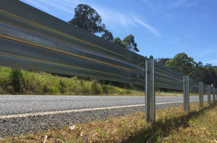
TIMBER FACED GUARDRAIL G4M AND G2M
SUMMARY
SUPPLIER: Commodore Trading (www.guardrailnz.com)
TEST LEVEL / CONDITIONS: NCHRP 350 TL2 (Tested to EN1317 N2 - 1500kg car at 110km/h and 20°)
PRODUCT MANUAL: Click for product manual download
FOR USE WITH Attaches to C100 anchor with terminal end rail.
STATUS Accepted (Not for use on State Highways)
Aesthetic semi-rigid barrier system comprising round timber facings over steel “C” section rails and driven steel posts.
The Timber Faced Guardrail G4m and G2m systems are considered suitable for use on local road networks with vehicle operating speeds up to
70km/h (equivalent to NCHRP Report 350 Test Level 2 (TL2) crash test conditions) at the discretion of the road controlling authority.
Not for use on State Highway network.
TECHNICAL INFORMATION
DIMENSIONS Post Spacing: 4m or 2m
Rail Height: 700mm ± 20mm above ground level height
MINIMUM LENGTH Timber Faced Guardrail was crash tested with a 60m length of barrier at 110km/h, however shorter
installations are commonly used.
OTHER RESTRICTIONS / Posts can be moved along the rail without affecting the rail integrity, if required to avoid
CONSIDERATIONS underground services, boulders or tree roots, on installation.
The Timber Faced Guardrail G4m and G2m are considered as visually appealing systems.
The crash testing performance has been assessed as equivalent to MASH TL2 and therefore it may
not be installed on State Highways.
The Timber Faced Guardrail is suitable where vehicle operating speeds do not exceed 70km/h.
The Timber Faced Guardrail G4m & G2m is terminated using a proprietary sloping end which
should be flared away from traffic, wherever possible, to mitigate risk of end-on impact.
COMMON FAULTS / OTHER CONSIDERATIONS
• Recommended installation is that the terminal end should be flared away from the road approximately +300mm.
• Whenever practical consider extending the rail and terminal end to achieve a greater flare.
• Currently no MASH or NCHRP 350 crash tested end terminal available.
• Handrail systems can be added at any height required for cyclists and pedestrians at discretion of road controlling authority.
• Back masks for the rail and posts are available to cover steel components at the rear of the Timber Faced Guardrail.NZTA M23A 2017 | 24
TIMBER FACED GUARDRAIL GRP
SUMMARY
SUPPLIER: Commodore Trading (www.guardrailnz.com)
TEST LEVEL / CONDITIONS: NCHRP 350 TL-2
Tested to EN1317 N2 - 1500kg car at 110km/h and 20° with 1.5, 2, 3, 4 & 6m post spacing
Tested as EN1317 H1 - 10000kg truck at 70km/h and 15° with 1.5m post spacing
PRODUCT MANUAL: Click for product manual download
FOR USE WITH Tested with a proprietary sloping end anchored to the ground.
STATUS Accepted (Not for use on State Highways)
Aesthetic semi-rigid barrier system comprising round timber facings (“masks”) over steel W-Beam guardrail and “C” section steel posts.
Timber Faced Guardrail GRP system is considered suitable for use local road networks with vehicle operating speeds up to 70km/h (equivalent to
NCHRP Report 350 Test Level 2 crash test conditions) at the discretion of the road controlling authority.
Not for use on State Highway network.
TECHNICAL INFORMATION
DIMENSIONS Post Spacing: 1.5, 2, 3 or 6m
Rail Height: 781mm ± 20mm above ground level height
MINIMUM LENGTH Timber Faced Guardrail was crash tested with an 84 metre length of barrier at 110km/h, however
shorter installations can be used.
OTHER RESTRICTIONS / The Timber Faced Guardrail GRP is considered as a visually appealing system.
CONSIDERATIONS The crash testing performance has been assessed as equivalent to MASH TL2 and therefore it may
not be installed on State Highways.
The Timber Faced Guardrail is suitable where vehicle operating speeds do not exceed 70km/h.
The Timber Faced Guardrail GRP is terminated using a proprietary sloping end which should be
flared away from traffic, wherever possible, to mitigate risk of end-on impact.
COMMON FAULTS / OTHER CONSIDERATIONS
• Recommended installation is that the terminal end should be flared away from the road approximately +300mm.
• Whenever practical consider extending the rail and terminal end to achieve a greater flare.
• This flare will mitigate the risk of end-on impact as there is currently no MASH or NCHRP 350 crash tested end terminal available.NZTA M23A 2017 | 25
LOGRAIL T18 4M/4MS2
SUMMARY
SUPPLIER: CSP Pacific (www.csppacific.co.nz)
TEST LEVEL / CONDITIONS: NCHRP 350 TL2 (Tested to EN1317 N2 - 1500kg car at 110km/h and 20°)
PRODUCT MANUAL: Click for product manual download
FOR USE WITH Tested with a proprietary 4m sloping end anchored to the ground.
STATUS Accepted (Not for use on State Highways)
Aesthetic semi-rigid barrier system comprising round timber facings over steel “C” section rails and driven steel posts.
The Lograil 4m and 4MS2 systems are considered suitable for use on local road networks with vehicle operating speeds up to 70km/h (equivalent
to NCHRP Report 350 Test Level 2 (TL2) crash test conditions) at the discretion of the road controlling authority.
Not for use on State Highway network.
TECHNICAL INFORMATION
DIMENSIONS Post Spacing: 4m (4M) or 2m (4MS2)
Rail Height: 700mm ± 20mm above ground level height
MINIMUM LENGTH 60m
OTHER RESTRICTIONS / Posts can be moved along the rail without affecting the rail integrity, if required to avoid
CONSIDERATIONS underground services, boulders or tree roots, on installation.
The crash testing performance has been assessed as equivalent to MASH TL2 and therefore it may
not be installed on State Highways.
The Lograil 4m and 4MS2 systems are suitable where vehicle operating speeds do not exceed
70km/h.
The Lograil 4m and 4MS2 systems are terminated using a proprietary 4m sloping end which
should be flared away from traffic, wherever possible, to mitigate risk of end-on impact.
COMMON FAULTS / OTHER CONSIDERATIONS
• Recommended installation is that the terminal end should be flared away from the road approximately +300mm.
• Whenever practical consider extending the rail and terminal end to achieve a greater flare.
• Currently no MASH or NCHRP 350 crash tested end terminal available.
• Handrail systems can be added at any height required for cyclists and pedestrians at discretion of road controlling authority.
• Back masks for the rail and posts are available to cover steel components at the rear of the Timber Faced Guardrail.NZTA M23A 2017 | 26
W-BEAM END TERMINALS
ET2000 PLUS END TERMINAL SYSTEM
SUMMARY
SUPPLIER: Ingal Civil NZ (http://www.ingalcivil.co.nz)
TEST LEVEL / CONDITIONS: NCHRP 350 TL2 and TL3
PRODUCT MANUAL: Click for product manual download
FOR USE WITH Attaches to permanent steel W-beam Barriers.
STATUS Accepted
The ET-2000 PLUS guardrail end terminal is used to absorb the kinetic energy of an impacting vehicle at a controlled rate. Upon impact, the
extruder head travels horizontally along the guardrail Beams, flattening the W-profile of the Beam and extruding the flattened section away
from the traffic face.
This system has been used in New Zealand as an end terminal for permanent road safety barrier systems for over 10 years. The ET-2000
PLUS End Terminal system, comprising of SYT Posts, has been tested in accordance with NCHRP Report 350 and is considered to comply
with the required evaluation criteria for Test Level 3 (TL3).
TL2 variant is available on request (not for use on State Highways).
TECHNICAL INFORMATION
DIMENSIONS 7.62m (Tl-2)
15.24m (Tl-3)
Post Height: 730mm +/- 20mm above ground level
SYT Post Spacing: 1905mm centres
WEIGHT TL2 Package Mass: 330kg
TL3 Package Mass: 540kg
MINIMUM LENGTH TL-2 system (70km/h) – 7.62m
TL-3 system (100km/h) – 15.24m
GRADE OR PLACEMENT Maximum approach and cross slope of 10H:1V
RESTRICTIONS
When installed at the end of guardrail following a curved alignment (offsets measured to the face of
the rail):
Outside of Curve: maximum offset 610mm from the curve.
Inside of Curve: maximum offset 305mm (curve radius of 300m or less)
maximum offset 610mm (curve radius greater than 300m)
Terminal grading in accordance with NZTA RSB-3
POINT OF REDIRECTION Length of need measured from point of redirection at Post #3
CLEAR AREA 6m x 22.5m clear area to enable the system to gate if impacted downstream from head
OTHER RESTRICTIONS / ET-2000 Plus is a tangential end treatment installed on a straight alignment.
CONSIDERATIONS Cannot be installed in front, on top or behind a kerb.
COMMON FAULTS / OTHER CONSIDERATIONS
• The first two posts from the end of the terminal have no offset blocking piece.
• The 200mm offset block used in the terminal is wider than conventional W-Beam offset blocking pieces.
• Provides redirection for side on impacts.NZTA M23A 2017 | 27
FLEAT 350 & SKT 350 END TERMINALS
SUMMARY
SUPPLIER: Safe Direction Ltd (www.safedirection.co.au)
TEST LEVEL / CONDITIONS: NCHRP 350 TL2 and TL3
PRODUCT MANUAL: Click for product manual download – FLEAT 350
Click for product manual download – SKT 350
Click for product manual download – SKT-SP and FLEAT-SP
Click for product manual download – FLEAT MT
FOR USE WITH W-beam guardrail
STATUS Accepted
The FLEAT 350 is a flared-only, energy absorbing end terminal that meets NCHRP 350 TL3. When impacted, the extruded guardrail curls
toward the traffic face.
The SKT 350 is a tangential-only, sequential kinking end terminal that also meets NCHRP 350 TL3. When impacted, the extruded guardrail
curls behind the barrier line.
The SKT-SP and FLEAT-SP are accepted variants of the SKT/ FLEAT 350 end terminals, using steel breakaway posts rather than timber posts.
The FLEAT-MT is a median terminal variation of the FLEAT 350 end terminal. It is available as wood or steel post options.
TL2 variants are available on request (not for use on State Highways).
TECHNICAL INFORMATION
DIMENSIONS TL2: 7.6m
TL3: 11.43m
Post Spacing: 1905mm centres
MINIMUM LENGTH TL-2 System(70km/h) 7.6m
TL-3 system (100km/h) 11.43m
GRADE OR PLACEMENT A maximum approach and cross slope of 10H:1V
RESTRICTIONS Terminal grading in accordance with NZTA RSB-3
POINT OF REDIRECTION Length of need measured from point of redirection at Post #3
CLEAR AREA 6m x 22.5m clear area to enable the system to gate if impacted downstream from head
OTHER RESTRICTIONS / Straight flare improves redirection in traffic face impacts
CONSIDERATIONS Variable offset of the FLEAT 350 reduces the need for site grading
The force required to push the impact head down the rail are lower than other tangent
end terminals
First Rail used must be a special kinking rail with slotted holes
760 to 1220mm offset needed for NCHRP 350 TL-3.
500 to 820mm offset needed for NCHRP 350 TL-2.
COMMON FAULTS / OTHER CONSIDERATIONS
• Drive-by system inspections are recommended at least monthly, and hands-on inspections are recommended at least yearly.
• Breakaway posts may be wood or steel, both are tested to NCHRP-350.NZTA M23A 2017 | 28
SOFTSTOP END TERMINAL SYSTEM
SUMMARY
SUPPLIER: Ingal Civil NZ (http://www.ingalcivil.co.nz)
TEST LEVEL / CONDITIONS: MASH TL-3
PRODUCT MANUAL: Click for product manual download
FOR USE WITH 790mm W-beam guardrail systems
STATUS Accepted
The SoftStop is an all-steel tangent end terminal for use with W-Beam guardrail systems. Using a proprietary head that flattens and extrudes
W-Beam guardrail upon end-on impacts within the MASH testing criteria, the SoftStop dissipates energy while guiding flattened rail through the
mouth at the bottom of the unit. The SoftStop end terminal is MASH Test Level 3 compliant as a re-directive, gating end terminal.
The SoftStop End Terminal can be assembled with a flare to offset the Head 600mm for the TL-3 system (300mm for the TL-2 system). The
flare must be over the length of the system. The maximum flare rate is 1:25.
TECHNICAL INFORMATION
DIMENSIONS TL-2 length: 7.89m
TL-3 length: 15.48m
System width: 180mm
System height: 787mm
Post Spacing: 1905mm centres
MINIMUM LENGTH 7.89m TL-2 system (70km/h)
15.48m TL-3 system (100km/hr)
POINT OF REDIRECTION Length of need measured from point of redirection at Post #3
CLEAR AREA 6m x 22.5m clear area to enable the system to gate if impacted downstream from head
GRADE OR PLACEMENT Maximum approach and cross slope of 10H:1V
RESTRICTIONS Flared or tangential terminal layouts acceptable.
Terminal grading in accordance with NZTA RSB-3
OTHER RESTRICTIONS / The core mechanism for dissipation of end impact energy is through anchorage and extrusion of
CONSIDERATIONS the W-Beam element.
COMMON FAULTS / OTHER CONSIDERATIONS
• The frequency of drive-by inspections is dependent on the traffic volume and the impact history of the system. Drive-by inspections are
recommended at least monthly.
• Hands-On inspections are recommended at least yearly.
• Splices at mid-span of the posts.
• Extruded rail is flattened and maintains connection to unit.
• Posts 2 through 8 should be the correct height of 813mm ± 20mm above ground level.NZTA M23A 2017 | 29
X-350 END TERMINAL SYSTEM
SUMMARY
SUPPLIER: CSP Pacific (www.csppacific.co.nz)
TEST LEVEL / CONDITIONS: TL3. NCHRP-350 TL-3
PRODUCT MANUAL: Click for product manual download
FOR USE WITH All semi-rigid longitudinal barrier systems.
STATUS Accepted
The X-350 End Terminal system is a re-directive guardrail terminal end that can be used in Median, Tangent or Flared
(up to 1200mm) installations.
The X-350 End Terminal system can be installed in the following configurations:
• Single-sided, installation height of 690mm (X-350), breakaway timber or steel posts;
• Single-sided, installation height of 790mm (X-350:31), breakaway steel posts only;
• Median (double-sided), installation height of 690mm (X-350 Median), breakaway timber or steel posts;
• Median (double-sided), installation height of 790mm (X-350:31 Median) breakaway steel posts only
The X-350 is considered redirective from post #1, but is classed as a gating terminal due to presence of ground strut upstream of post #1.
TECHNICAL INFORMATION
DIMENSIONS 11.43m (3 rails)
690mm or 790mm to suit guardrail system
WEIGHT Impact Head weight: 25kg
MINIMUM LENGTH 11.43m (3 rails) TL-3 system (100km/h)
GRADE OR PLACEMENT Maximum approach and cross slope of 10H:1V
RESTRICTIONS Flared or tangential terminal layouts acceptable.
Terminal grading in accordance with NZTA RSB-3
POINT OF REDIRECTION Length of need measured from point of redirection at Post #1
CLEAR AREA 6m x 22.5m clear area to enable the system to gate if impacted downstream from head
OTHER RESTRICTIONS / X-350:31 must be used with Nu-Guard® 31
CONSIDERATIONS Site specific grading must be provided in accordance with NZTA detail RSB-3 to ensure that there
are no “humps” or “hollows” that may significantly alter stability of the impacting vehicle.
Impact force held in tension.
Gating and Re-directive system.
0 – 1200mm offset for all variations of the end terminal.
COMMON FAULTS / OTHER CONSIDERATIONS
• When a X-350 End Terminal is installed in a trailing/exit location, where the terminal head is facing away from the direction the vehicle
is travelling, the splice join at rails 1, 2 and 3 of the terminal will be against the direction of traffic.
• Nut Protectors are available.
• Plastic Front End Cover is available for both roadside and median terminal ends.NZTA M23A 2017 | 30
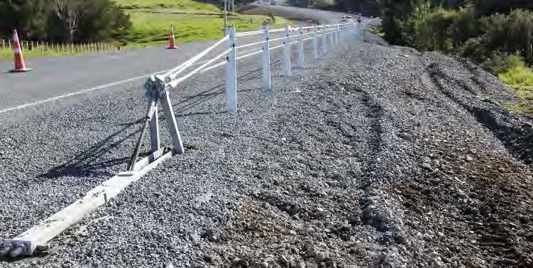
TRAILING TERMINAL
SUMMARY
SUPPLIER: Open source – no specific supplier
Proprietary variants available for Ezy-Guard 4 and Nu-Guard® 31
TEST LEVEL / CONDITIONS: n/a (non-crashworthy, anchorage only)
PRODUCT MANUAL: Click for product manual download
FOR USE WITH Only to be used to anchor the end of a semi-rigid W-Beam barrier system.
STATUS Accepted
The purpose of the Trailing Terminal is to anchor the end of a flexible rail system to keep the tensile strength in the rail.
Trailing Terminals are intended to provide anchorage for the barrier. They are not crashworthy terminals when struck head-on, since they are
not designed to absorb energy or break away. They must not be installed where there is a likelihood they could be impacted head-on by an
errant vehicle.
The Curved Trailing End Terminal (CTT) should be used as the default. The Straight Trailing End Terminal (STT) should only be used where
space constraints prevent use of a CTT.
TECHNICAL INFORMATION
DIMENSIONS Length of terminal: 3.81m
System Height: 706mm for public domain or 787mm for proprietary variants
Post Depth: 1100mm minimum
Post Spacing: 1905mm
MINIMUM LENGTH 3.81m
OTHER RESTRICTIONS / Bullnose required on CTT and STT. Rolled end fitting not allowed
CONSIDERATIONS Minor site grading may be necessary for guardrail installations beyond the edge of the shoulder to
prevent the steel posts from extending more than 100mm above the ground.
The CTT has an offset at the bullnose of 335mm.
COMMON FAULTS / OTHER CONSIDERATIONS
• The CTT used in a leading situation does not comply with any current NZ Transport Agency standards and can only be used in special
cases for low volume, low speed with permission of road controlling authority.You can also read