APBA American Power Boat Association - 2020 Modified Outboard Technical Manual March 28, 2020 - American Power Boat ...
←
→
Page content transcription
If your browser does not render page correctly, please read the page content below
APBA
American Power Boat Association

              2020

       Modified Outboard
       Technical Manual

           March 28, 2020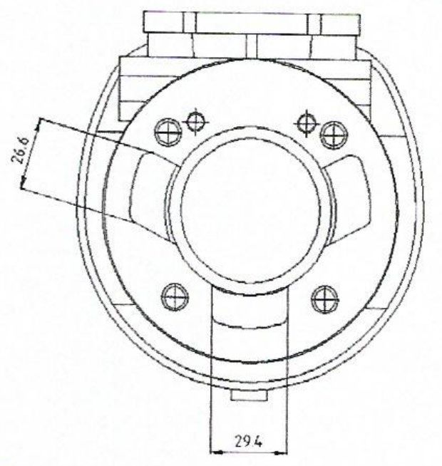
2020 MODIFIED OUTBOARD TECH MANUAL

                            PERMISSIBLE MODIFICATIONS AND RESTRICTIONS

The terms, specifications, and specification sheets as used in the following rules refer only to the “Official Modified
Outboard Specification Sheets” included in this book. THESE DIMENSIONS AND TOLERANCES COMBINED
WITH THE MODIFIED OUTBOARD RULES LISTED BELOW ARE THE ONLY TECHNICAL LIMITATIONS TO BE
PLACED ON THE ENGINE BY INSPECTORS. The exception to this are the 200 cc Modified, 400 cc Modified, and
850 cc Modified classes. It is to be clearly understood that all engines, parts, etc. must comply with the dimensions
and tolerances shown on the “Official Modified Outboard Specification Sheet”. In cases of conflict, the specific class
rules shall apply.

1.     Any type or make of nut, bolt, screw, washer, spark plug, piston ring, propeller, ring pin, fuel line, fuel line
       fittings, starter plate, spacer plate assembly and ignition parts may be used.

2,     The removal of integral gas tanks, spray shields, protective cowlings, spark plug protectors, compression
       release valves, fuel filters, starters and their mechanisms and carburetor chokes is permitted.

3.     Motors may be modernized with the use of parts manufactured for later model motors of the same class.
       However, if new parts differ from Modified Outboard specification sheets, approval of MORC is required. The
       interchange of parts from one motor to another in these classes is not permitted except where the
       manufacturer provides interchangeable parts. Crankcase assemblies, for service use or stock racing, with
       2.125 stroke, are to be considered interchangeable in the 250 cc and 350 cc Modified classes.

4.     Open exhaust and special built or tuned exhaust systems are permitted. The addition of material to seal filler
       blocks and plug water outlets in blocks is permitted. Any new engines approved for use in the Modified
       category are not allowed to use open megaphone type exhaust systems.

5.     Any make or material fabricated motor driveshaft housing and any make or type of clamp and swivel bracket
       is permitted.

6.     The addition of metal to any drive shaft housings and lower unit gear housings is permitted for the specific
       purposes of strengthening these parts.

7.     The addition of material for the specific purpose of installation of cavitation plates to drive shaft housings and
       spray shields and gas tanks to motors is permitted.

8.     It is permitted to rotate the powerhead on the downhousing in all classes except 200 cc Modified.

9.     Any make/material reed cage is permitted in mercury motors provided the following criteria is met:

       a) Reed number, size, placement and design are the same as stock cage.
       b) The crankcase does not have to be altered to accept the new cage.
       c) No extra ports or passages are created in design.
       d) Lies within specifications which will be shown on the official specification sheet
       e) Size of reed port openings shall be measured 3/32 in. below the surface of the reed cage or near the
       surface if the opening is smaller there.

10.    Any Mercury or Quincy production reed block may be used in any Mercury motor as long as it complies with
       specifications on the Official Modified Outboard Spec Sheet for the class, including the center main bearing
       surface. It is permitted to fill in oil slots and add material for the specific purpose of increasing the exterior
       diameter (The intent being to insure a tight fit/seal between the reed block exterior diameter and the
       crankcase). Any and all surfaces of reed cages may be coated with neoprene or a suitable “plastic” to a
       maximum thickness of 0.040”.

                                                            1                                                      3-10-20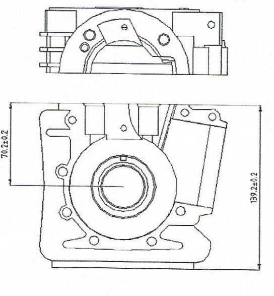
2020 MODIFIED OUTBOARD TECH MANUAL
11.   It is not permissible to add material (including chrome plate) to cylinder walls.

12.   Re-sleeving of cylinders is permitted.

13.   Cylinder diameters may be bored, honed or ground to a maximum of 0.050” larger than the manufacturers
      mean dimension as listed under “G” in the motor specification sheets. Off center or slant boring of cylinders
      from normal stock center lines and perpendiculars is not permitted.

14.   Broken or damaged parts may be repaired by welding or the use of plastic epoxy compounds, provided that
      all internal dimensions, contours and surfaces or parts are restored as closely as possible to original
      condition, within specifications. The inspector will pass repairs that meet the word and spirit of this rule and
      will disqualify engines having repairs which are obviously intended to provide an unfair advantage.

15.   Material may be added to or removed from flywheels for balancing purposes. Service engine flywheels may
      be machined down to racing size and weights, provided the weight of such flywheel is not reduced to less
      than the minimum specified for that class engine. Flywheel must not be interchanged between classes
      unless specifically intended by the original engine manufacturer.

16.   Removal of material from non-reciprocating parts (pistons and rod assemblies are classified as reciprocating)
      is permitted except as noted in these rules and specification sheets.

17.   Removal of material from reciprocating parts, except for balancing and polishing is prohibited except where
      permitted in these rules and specification sheets.

18.   The polishing of moving parts and passages is permitted except where prohibited by individual class rules
      and specification sheets.

19.   Beveling of crankshafts is permitted except where removal of material is prohibited by individual class rules
      and specification sheets.

20.   No extra ports or passageways are allowed in the powerhead except where permitted in individual class rules
      and specification sheets.

21.   Enlarging of intake and exhaust ports is permitted except where prohibited by individual class rules and
      specification sheets.

22.   Removal of material by drilling holes, etc., into combustion chambers for the purpose of introducing water in
      that area is prohibited.

23.   Indexing of pistons is permitted with the tolerances as specified in the “E” and “EE” measurement for that
      specific engine.

24.   The addition of material for any purpose is prohibited except as noted:

      a) Elsewhere in these modified rules specifically.
      b) Addition of material to the outside of piston skirts is approved, specifically meaning “coating” of skirts OD
      with a material to increase diameter, except the 25xs motor running in 350ccMR.
      c) Primers may be added and gas fittings installed in any carburetor or reed cage area. It is not permitted to
      use this as an accelerator pump or power jet.
      d). Addition of thermal barrier coatings to piston crowns is approved. However crown dimensions must
      remain as manufactured.
      e). It is permissible to reposition the ring groove stop pin to allow the use of the Model 300 series piston in the
      Yamato 102 motor.

                                                           2                                                    3-10-20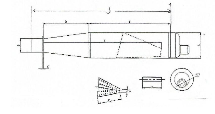
2020 MODIFIED OUTBOARD TECH MANUAL

25.     Alterations to carburetor and fuel systems are permitted as follows:

        a). For marathon use, an auxiliary fuel supply connection may be added to the carburetor.
        b). The butterfly or idling needle must be altered as necessary in order for the automatic cut-off throttle to
        function properly.
        c). Adapters or extra length high-speed needles are permitted.
        d). Any inlet needle and seat may be used in any carburetor.
        e). Material may be added to stiffen float levers in Carter model N carburetors.
        f). Filters or fuel pressure regulators may be added to any fuel line.
        g). All KA model Tillotson carburetors having a one inch venture are legal for use on all class 250 cc, 350 cc,
        and 750 cc Modified engines provided they measure within KA7A model specifications and the use of
        adjustable high speed needs and seats from KA7A carburetors and conversion kit no. 2619A1 is permitted.
        h). Fuel line cooling units are permitted.
        i) With the exception of Mercury engines running in the 250cc modified classes, aftermarket float bowl covers
        are allowed on Mercury carburetors provided that the carburetor body is not altered to accommodate the float
        bowl cover.

26.     Two piece driveshafts are permitted and modifications to adapt approved lower unit gear housing to
        driveshaft housings are permitted.

27.     Lower unit gear housings may be reduced to measurements as shown on the motor specifications sheets.
        Except for 200 cc Modified classes, the addition or removal of material on gear cases is permitted as long as
        “R” and “S” dimensions are maintained.

28.     There are no water pump specifications on Mod gear units.

29.     After market pistons are permitted for use in all classes. However, they must meet all specifications for the
        class.

30.     Any make fuel pump is legal on any Modified motor.

31.     It is permissible to tack weld repair any multiple piece crankshaft for the purposes of maintaining alignment.

HULLS

1.      RUNABOUTS

                                     200 cc, 250 cc, 350 cc, and 500 cc Modified

        a.     Boats in these classes are defined as displacement type hull; having no step, no breaks in the
               longitudinal or transverse continuity of the immersed surface other than the keel, rubbing strips or
               lapstrake of no greater than ¾” and parallel to the center line of the boat.
        b.     Boats in these classes will not be permitted to depend on external air pressure or designs which
               create a “tunnel” effect to aid planing.
        c.     Turning fins may be used.
        d.     Runabouts will not be required to have a forward cockpit and are not required to conform to any
               maximum or minimum dimension restrictions.
        e.     Transverse concavity of runabout running surface of 1/32” per foot (12”) as measured from high point
               to high point across running surface width is permitted.
        f.     Any runabout hull permitted for racing in the Stock Outboard Division of APBA shall be permitted in
               the Modified Division.

                                                           3                                                    3-10-20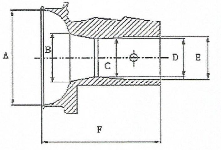
2020 MODIFIED OUTBOARD TECH MANUAL
     g.      On “Deep V” runabouts having a positive dead rise angle of more than 10 degrees rule 1-E will not
             apply. However the following restrictions will apply to those hulls.

             1.     The maximum width of running pad (keel) is 10”
             2.     Surfaces with negative dead rise angles are not permitted.
             3.     Stability strakes with a maximum depth of 1” are permitted, but placement of said strakes
                    specifically to trap air are prohibited.

     h.      Hulls shall not have a sponson/pod protruding from the side of the boat which interrupts the line of the
             side, bottom, or non-trip of the boat. Turning fins and turning fin brackets on 850 cc and 750 cc
             runabouts may not protrude more than one (1) inch beyond the chine of the hull where it is mounted.
     i.      Lifting rails such as those used on DeSilva “Pro” racing runabouts are permitted.

     j.   Some 1985-1987 DeSilva model KR runabouts have a concave tunnel in the right chine (see diagram)
          and are permitted in the Modified category. However hulls having a tunnel chine in both sides are not
          permitted.

     The drawings below are to be enforced for the 200 cc Modified, 250 cc Modified, 350 cc Modified, and 500 cc
     Modified runabout classes only.

     750 cc and 850 cc Modified RUNABOUT RULES

     K.      The 750 cc and 850 cc Modified runabout racing hull must conform to the following:
             a.    The bottom shall have no steps or breaks in the longitudinal continuity.
             b.    The bottom must not have any of the following:
                     i.      Tunnel
                     ii.     A concavity greater than one-sixteenth (1/16) of an inch within the planning surface
                     iii.    Any design that uses a tunnel effect
             c.    The side of the boat must form a continuous contour from a single stem to transom and must
                   have no concavity greater than one-quarter (1/4) inch. The side of the boat referred to in
                   Section “c” shall be interpreted as the outside chine.
             d.    Trim tabs which are adjustable by the driver while underway shall not be allowed.
             e.    Rub rails will be allowed provided:
                     i.      They are attached to the extreme outside of the boat
                     ii.    They do not exceed 1.5” in depth and width

     l.     Runabout length shall be measured from top of transom along centerline to tip of bow excluding any
     hardware or other devices added to the boat to extend its overall length. Length in 750 cc and 850 cc
     Modified shall be 12’ minimum.

2.   HYDROPLANES

                                                         4                                                   3-10-20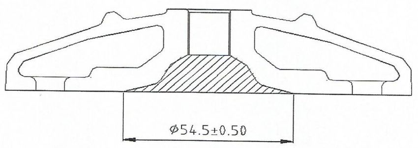
2020 MODIFIED OUTBOARD TECH MANUAL
      a.      Any boat having multiple planning surfaces and which cannot quality as a runabout will be considered
              a hydroplane. This shall specifically include “tunnel boats” as permitted hydroplanes in this Division.
      b.      Turning fins are permitted.
      c.      There shall be no specifications or restrictions placed on hydroplanes in this Division except:
              1.     Effective November 1, 2007, all MO hydroplane hulls shall have a construction date
                     permanently affixed to the inside of the transom in a location easily visible to the Inspector. (If
                     the actual construction date of a hull is unknown, a one-time declaration of a construction date
                     (month and year) may be permanently affixed by the owner or driver to the inside of the
                     transom.)

              2. All MO hydroplane hulls built after October 31, 2007 will have the foremost points of sponson
                 pickleforks that meet the following requirements for shape. The foremost points of the pickleforks
                 shall have a minimum radius of 1" in one view. This minimum radius shall extend at least 45
                 degrees to both sides of the foremost point. At 90 degrees to this radius conforming view, the
                 foremost points on the picklefork will have a minimum thickness of ¾". This minimum thickness
                 shall extend at least 45 degrees to both sides of the foremost point.

              3. All MO hydroplane hulls built after October 31, 2007 where the cockpit nose extends forward of
                 the body of the hull, shall have a cockpit nose that conforms to the same requirements for shape
                 as the picklefork foremost points described in paragraph 2 above.

              4. Half oval aluminum rub molding may be used around the foremost points of pickleforks and
                 cockpit noses provided the molding is at least ½" in width.

              5. This Rule does not apply to hulls that conform to runabout specifications, conventional round-nose
                 hydroplane hulls without pickleforks or sponson noses that extend forward of the body of the hull,
                 or tunnel hulls that conform to OPC specifications for collapsible sponson noses.

3.    All laydown boats shall have left and right mirrors positioned in such a way that they allow rear vision from the
      driving position. Each mirror must be a minimum of six (6) square inches of reflective surface. Mirrors are
      not required during kilo trials. In the event a mirror is displaced or broken during racing, replacement is not
      required until the next attended event.

4.    GENERAL RULES

      a. Planning surfaces, fins, motor tilt devises, and devices which can raise and lower engine height on the
         transom, any or all of which are moveable or controllable while under way are not permitted. For such
         devices to be permitted, it must be construction in such a manner as to require the driver to shut off the
         engine and stop the boat before adjustment is possible.

      b. Overall weight requirements:
             1. Boat stepping up into a larger class shall be required to have only the overall weight of its own
                class.
             2. As a safety item to encourage the use of “cut suits” (e.g. Kevlar) overall racing weights for boats
                are as follows:
                                          MINIMUM BOAT WEIGHTS
        CLASS                      WEIGHT                        CLASS                        WEIGHT
      125 cc MH             350 lbs (2018 MORC)                125 cc MR              350 lbs (2018 MORC)
      200 cc MH                     345 lbs                    200 cc MR                       350 lbs
      250 cc MH                     365 lbs                    250 cc MR                       360 lbs
350 cc MH with Hot Rod              370 lbs             250 cc MR with Merc 20                 360 lbs
350 cc MH with 20 cu in             350 lbs            350 cc MR with Hot Rod                  390 lbs
         Merc
                                                          5                                                     3-10-20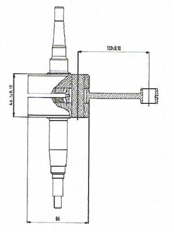
2020 MODIFIED OUTBOARD TECH MANUAL
 350 cc MH with 400 cc                  395 lbs             350 cc MR with 20 cu in               370 lbs
      Mod motors                                                      Merc
  350 cc MH with Y-80                   420 lbs              350 cc MR with 400 cc                390 lbs
                                                                  Mod motors
         500 cc MH                     440 lbs.               350 cc MR with Y-80                 415 lbs
     750 cc MH 40 cu in                450 lbs               350 cc MR with 25XS                  395 lbs
                                                                      Merc
  750 cc MH 44 cu in                    470 lbs                    500 cc MR                      480 lbs
      400 cc MH                         370 lbs                750 cc MR 40 cu in                 475 lbs
400 cc MH with Merc 20                  350 lbs                750 cc MR 44 cu in                 475 lbs
      850 cc MH                          None                      850 cc MR                       None

        c. Scales at races cannot be protested, but must be available for use one (1) hour before the start of the first
           heat of each day’s racing.

        d. Any device may be used as a brake as long as its sole purpose is to reduce the speed of the boat.
              1. If a brake is used it must be mounted within 8” of the centerline (or keel) at the transom and be
                 mounted on the starboard side. Brakes must be in a “neutral” mode and have no effect on turning.
                 The aspect ratio of any brake (side view/front view ratio) may not be more than 1.5:1

        e. The 850 cc Modified class can use a transom rudder system for steering purposes which is not
           retractable and cannot be elevated while underway.

        f.   All fuel tanks must have an opening sufficient for a Digitron fuel meter probe to pass unobstructed into the
             fuel tank. 1.050 is the diameter of the probe.

        g. All weights must be securely fastened to the hull.

                                                                FUEL

1.      Permissible fuels for use in the Modified Outboard classes shall consist of gasoline and oil only. Gasoline
        may be aviation, automobile, of either leaded or unleaded varieties and includes automobile racing gasoline
        so long as it does not contain alcohol, nitrates, oxygen bearing compounds or other such power boosting
        additives. Gasohol is not a permitted fuel. Oils may be petroleum or synthetic and cannon contain power
        boosting additives. All oil must be made for 2-cycle engines. Any driver using a fuel which does not meet
        this rule will be disqualified. Additional fuel disqualification in the same day will result in the driver being
        automatically suspended for the remainder of the day.

2.      At each Regatta, the Inspector may purchase a sample of local gasoline, mix it with TC III oil at a ratio of 8:1
        and test it according to the Tech Manual. If the test fuel exceeds the 0 Digitron DT-15, DT-47 or FT-64
        threshold, the higher reading will become the maximum limit of the day. The source and grade of the
        gasoline must be announced when Registration opens. At that time, testing equipment must be available to
        all competitors. The Fuel of the Day is not applicable at straightaway or Record races, Championships, or
        National events (Nationals, Winter Nationals, Divisionals, Regionals).

                                               LEVELS OF INSPECTION

        Level 1 – At all races, Inspection shall consist of:

                    •   Height
                    •   Weight
                    •   Tuck
                                                            6                                                     3-10-20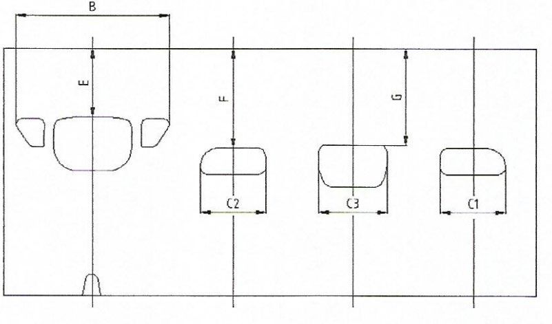
2020 MODIFIED OUTBOARD TECH MANUAL
                    •    Fuel checked with the Digatron meter

        Level 2 – At Divisionals, Championships (formerly Winter Nationals, and North American
        Championships:

                         •   All items in a Level 1 Inspection plus
                         •   Gearcase Letters R & S and check the ratio
                         •   Check bore and stroke
                         •   Measure the carburetor throat and venturi
                         •   The combustion chamber volume must be measured

        Level 3 – Summer Nationals and Record Races

                             •   All items in a Level 1 and Level 2 Inspection plus
                             •   Internal Inspection to verify that internal dimensions comply with current
                                 Modified rules. (2020 Commission)

                                            FUEL TESTING PROCEDURES

       Fuel testing procedures used may be one or all of the following methods and are at the discretion of the
Inspector. The tests are as follows:

               a.        Digatron DT-15, Digatron DT-47, or Digatron FT-64 Meter
               b.        Specific Gravity
               c.        Water Solubility
               d.        Germaine Reagent Fuel Test
               e.        Ceric Nitrate Fuel Test

                        DIGATRON DT-15/47-FT/FT-64 FUEL METER TESTING INSTRUCTIONS

        The purpose of this test is to measure certain electrical properties of the fuel sample and determine if they
are within the permissible limits.

      The test procedures described here are in accordance with the instructions supplied by the DT-15 Meter
manufacturer.

Before performing your fuel test, ensure that the fuel meter is in good working order:

   a.      Sensor Condition – Visually check the sensor and its connecting wire to assure that is has not been
           physically damaged.
   b.      Battery Condition – When the meter is on, the words “LO BAT” will appear in the upper left hand corner of
           the display if the battery needs to be replaced. Do not use the meter if the “LO BAT” message is
           displayed, as its readings will not be accurate.

The recommended fuel test procedure is as indicated below:

   1.      Calibrate the DT-15 and 47-Ft meters as follows:

                                                           7                                                    3-10-20
2020 MODIFIED OUTBOARD TECH MANUAL
a. Turn the meter on and allow it to warm up for at least 15 minutes before doing any testing. This will
allow the internal components to stabilize at their normal operating temperature.
b. Attach the sensor’s connecting wire to the meter. Hold the sensor’s connecting wire and lower the
sensor into the calibration liquid (Cyclohexane – C6H12) in such a way that the sensor is completely
submerged. Take care to assure that the sensor is not in contact with the fuel container. Gently
wiggle the sensor wire to displace any air bubbles which may be trapped between the sensor plates.
Using the knob on the front of the meter, adjust the meter until the display reads “-75”.
2. Calibrate the FT-64 meter as follows:
a. Press Exit/Power button
b. Press Set button andhold 2 seconds. SEL/SEL will start blinking.
c. Press both Light and Set buttons at the same time to enter the calibration mode.
d. Place probe in appropriate amount of cyclohexane in a plastic or glass container.
e. Press the Up or Down arrows to adjust to -75.0.
f. Press the Exit/Power button to exit calibration.
3. Remove the sensor from the calibration liquid, and dry any excess liquid from between the sensor plates.
Lower the sensor into the fuel sample just like you did while calibrating the meter. Observe the reading
on the meter’s display. If the reading is zero or a negative number, the fuel is permitted. If the reading is
greater than zero (a positive number) the fuel is not permitted.
The electrical characteristics of gasoline change somewhat with temperature. As such, it is important that the
temperature of the fuel sample and the calibration liquid be within about 15° of each other.
When a fuel sample is found to be in violation of these rules per the above procedure, it is recommended the
following steps be performed:
a. Clean the sensor with some spray-on brake cleaner and allow it air dry for at least 30 seconds.
b. Recheck the calibration setting (-75) of the meter in the Cyclohexane and adjust the meter if necessary.
c. Allow the fuel sample to stabilize to the same temperature as the Cyclohexane, then repeat the test as
described in #3 above.
During the course of the day, it is recommended that the calibration setting in the Cyclohexane be occasionally
checked. It is interesting to note that calibration reading of “-75” in the Cyclohexane has a corresponding reading
when the sensor is in the air. Although this corresponding air reading varies between individual meters, it tends to
be quite consistent for each particular meter. As such, the specific corresponding air reading, for the particular meter
being used, can be a useful reference during the time between occasional Cyclohexane calibration checks.
SPECIFIC GRAVITY TESTING INSTRUCTIONS
The purpose of this test is to measure the relative density of the fuel sample and determine if it is within the
permissible limits.
Two pieces of equipment are required to perform this test:
1. Specific gravity hydrometers which cover the range of 0.750 – 0.800 ( at 60° F).
2. A clear glass container which is at least as tall as the hydrometer. A “graduated cylinder” works well for
this purpose.
The recommended fuel testing procedure is as indicated below:
a. Assure that the glass container and hydrometer are clean
b. Place the glass container on an essentially level surface and fill it with the fuel which is to be tested. The
depth of the fuel should be equal to, or greater than, he length of the hydrometer.
c. Carefully insert the hydrometer into the fuel sample with the weighted end facing down. Take care to
minimize the contact between the hydrometer and the container.
8 3-10-202020 MODIFIED OUTBOARD TECH MANUAL
d. When the hydrometer has reached a stable free float in the fuel sample, read the specific gravity from the
scale within the hydrometer. This is done by visually sighting along the upper surface of the fuel and
reading when the scale crosses the fuel’s surface. Record this reading.
e. Measure the temperature on the fuel.
f. The specific gravity characteristics of fuel (gasoline and oil) change somewhat with temperature. As
such, the maximum permissible specific gravity reading will change as the fuel temperature changes.
Following is a listing of the maximum permissible specific gravity readings and their corresponding fuel
temperatures.
Fuel Temperature in Maximum Permissible Fuel Temperature in Maximum Permissible
Degrees Fahrenheit Specific Gravity Reading Degrees Fahrenheit Specific Gravity Reading
40 .785 80 .766
50 .780 90 .761
60 .775 100 .757
70 .771 110 .752
WATER SOLUBILITY TESTING INSTRUCTIONS
The purpose of this test is to determine if water soluble additives are present in a fuel sample.
The only piece of equipment necessary to perform this test is a graduated container. It is recommended that a good
quality glass “graduated cylinder” be utilized, with the capacity of 100 ml and subdivisions of 1.0 ml or less.
The recommended testing procedure is as indicated below:
a Assure that the graduated container is clean.
b. Place the graduated container on an essentially level surface.
c. Pour approximately 35 ml of the fuel sample into the graduated container.
d. Carefully measure and record the amount of fuel in the container (using the scale on the container)
e. Slowly pour approximately 35 ml of water into the container.
f. The liquid in the container will separate into two layers. The water will settle to the bottom of the container,
carrying any water soluble additive with it. Often a froth will form in the lower layer. As such, allow some
time for the froth to clear.
g. Carefully measure and record the total amount of liquid in the container.
h. Subtract the amount of fuel in the cylinder (item d) from the total liquid (item g) to determine the exact amount
of water which was added. Record this result.
i. Carefully measure the amount of liquid in the lower layer of the container.
j. If the amount of liquid in the lower layer (item I) is greater than the amount of water added (item h), the fuel
contained water soluble additives and is not permitted.
THE GERMAINE REAGENT TEST
Equipment Required:
a). Disposable test tubes
b). Disposable eyedroppers or pipettes
c). Test tube rack suitable to hold test tubes above.
d). Protective latex or rubber gloves.
e). Bottle of Germaine reagent
9 3-10-202020 MODIFIED OUTBOARD TECH MANUAL
Optional:
a). A bottle of 1,4 Dioxane
b). A bottle of known legal fuel
Specified Procedure
1. Using a new, clean pipette or eye dropper, draw a fuel sample from competitor’s tank or fuel line and fill
test tube approximately 2/3 full. Always use a new pipette and a new test tube for each competitor.
1. Wearing protective latex or rubber gloves, carefully squeeze one drop of Germaine Reagent directly into
the center of the fuel sample in the test tube. Do not allow reagent to run down the side of the test tube,
as it makes reading the test more difficult.
NOTE: Most users will find the test easiest to read by holding the tube up at eye level when the reagent is added to
make viewing any reaction more convenient.
2. When the Germaine reagent drop first hits the fuel sample, any oil dissolved and/or suspended in the
gasoline will come out of solution and fall immediately to the bottom of the test tube. This is not a positive
reaction. Different oils may react differently, but a single, fast falling drop of oil is typical.
3. The formation of a white or light brown precipitate (like little snowflakes) at the point where the Germaine
Reagent hits the fuel sample is a positive indication of the presence of 1,4 dioxane. The precipitate will
drift, depending on size and density, to the bottom of the test tube. Within a few minutes it will darken
from contact with oil drop in the bottom of the tube.
4. It is always advisable to repeat a positive test to insure than no error has been made.
5. It is a good practice to carry a sample of known legal fuel and a sample of 1,4 dioxane to use as a
verifying test. Simply make up 3 test tubes, one containing the known legal fuel, one containing known
legal fuel to which you then add some 1,4 dioxane, and one containing the competitor’s fuel. Then repeat
the test, observing any reaction in the known legal sample, then the known legal sample containing 1,4
dioxane, and finally the competitor’s sample. Having observed the reaction of the sample known to
contain 1,4 dioxane, it will be easier to confirm the reaction in the competitor’s sample.
CERIC NITRATE FUEL TEST
The purpose of this test is to determine if alcohol is present in a fuel sample.
Following is a list of special equipment necessary to perform the test.
50 ml graduated cylinder with subdivisions of 1.0 ml (or less)
100 ml glass beaker
18 mm x 150 mm clear glass test tube
2 ounce glass dropper bottle with dropper assembly
Following is a list of the chemicals necessary to perform this test:
Ceric Ammonium Nitrate (NH4)2Ce(NO3)6
Nitric Acid (HNO3), 70%
10 3-10-202020 MODIFIED OUTBOARD TECH MANUAL
The reagent solution should be made prior to the race (within a couple of days and is done as follows:
1. Pour 41 ml of distilled water into the glass beaker.
2. Carefully add 9.0 ml of Nitric Acid to the water in the glass beaker.
3. Add 20 grams of Ceric Ammonium Nitrate to the solution in the glass beaker.
4. Dissolve the Ceric Ammonium Nitrate by gently stirring. Slight heating of the solution will speed the
process; however, DO NOT BOIL!
Pour the Reagent Solution into the dropper bottle and secure the cap. The Reagent Solution should have a yellow
color.
Recommended fuel test procedure:
1. Pour approximately 10 ml of the fuel sample into the test tube.
2. Carefully add six (6) drops of the Reagent Solution to the fuel sample in the test tube.
3. Seal the open end of the tube and invert several times.
4. The Reagent Solution should accumulate at the bottom of the test tube. Observe the color of the
accumulated Reagent Solution. If it is the same color (yellow) as the original solution in the dropper
bottle, the fuel sample contains no alcohol. If the accumulated Reagent Solution in the test tube has
changed from its original color (yellow), the fuel sample is not legal.
COMBUSTION CHAMBER VOLUME FLUID MEASURING LIQUID
A mixture of 50% Mineral Spirits and 50% Marvel mystery Oil shall be used to measure the combustion
chamber volume. (2020 Commission)
11 3-10-202020 MODIFIED OUTBOARD TECH MANUAL
125 cc MODIFIED CLASSES
It is the intent of the Modified Outboard Commission that the engine in this class be raced as received from
the manufacturer and the MORC, with the modifications as specifically allowed in these rules.
1. Used Fireball motors are legal provided all specifications are met.
2. Any questionable part may be compared to a known legal part to determine legality.
3. The motor must have the “US” stamp on the crankcase.
4. Aftermarket starter bendex cover and starter ring gear cover are permitted.
5. Starter switch affixed to motor must have a shield to prevent accidental engaging of the
starter. (2020 Commission).
6. Any length exhaust adapter may be used between the supplied header and supplied pipe.
(2020 Ballot)
7. A 3/16” maximum hole may be drilled at the bottom of the end cap of the exhaust pipe to
permit drainage of any trapped water. (2020 Ballot)
Bore 53.68 mm Standard
Stroke 54.0 mm
Minimum cc’s 10.0 cc
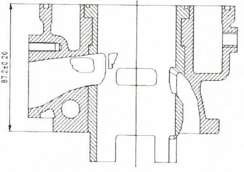
Squish Band Diameter 54.5 +/- 0.050 mm
Cylinder Length 87.2 +/- 0.020 mm
Crankcase Length 139.2 +/- 0.020 mm
Split line length of Crankshaft
70.2 +/- 0.020 mm
Center to Cylinder Surface
Rod Length (Center to Center) 100 mm +/- 0.10 mm
Rod Weight 100 grams +/- 5 grams
Piston Length Skirt to Edge of Crown 58.8 +/- 0.070 mm
Wrist Pinhole Center to Edge of Piston
29.8 +/- 0.070 mm
Crown
Piston Weight 135 grams +/- 5 grams
Exhaust Port Height 34.5 +/- 0.20 mm
Transfer Port Heights 44.4 +/- 0.20 mm
Boost Port 46.25 +/- 0.20 mm
Gasket between Cylinder and Crankcase
0.005 inch Minimum
Thickness
12 3-10-202020 MODIFIED OUTBOARD TECH MANUAL
CYLINDER SECTION CYLINDER BASE
CRANKSHAFT INTERIOR VIEW OF SUMP
Complete Weight = 1975
grams
Tolerance = ± 10 grams
13 3-10-202020 MODIFIED OUTBOARD TECH MANUAL
CYLINDER HEAD AND COMBUSTION CHAMBER
CYLINDER DEVELOPMENT
B- 65.3 mm
C1 = C2 - 26mm
C3 - 29.4 mm
Angular readings by inserting a
0.20 mm gauge
E - 33.5 mm
F - 43 mm
G - 43 mm
± 0.20mm ON ALL CAST MEASUREMENT
14 3-10-202020 MODIFIED OUTBOARD TECH MANUAL
PISTON CONNECTING ROD
Weight = 135 grams (± 5 Weight = 100 grams (± 5
grams tolerance) grams tolerance)
CARBURETOR DIMENSION
A – 33.75 mm
(±
--------
C – 24.0mm
(±0.10mm tolerance)
D – 24.00mm
(±0.10mm tolerance)
E – 27.00mm
(±0.10mm tolerance)
F – 66.25mm
(±0.10mm tolerance)
15 3-10-202020 MODIFIED OUTBOARD TECH MANUAL
DRAWING OF THE SILENCER AND ITS COMPONENTS
Measurements
A – 100 mm
B – 54 mm
C – 3 mm
D – 170 mm
E – 315 mm
F – 170mm
G – 21mm
(±0.50 mm tolerance on all measurements)
H – 135mm
I – 455 mm
J – 520mm
EXHAUST HEADER
16 3-10-202020 MODIFIED OUTBOARD TECH MANUAL
200 CC MODIFIED CLASS
It is the intent of the Modified Outboard Commission that the engine in this class be raced as received from the
manufacturer, with the exception of modifications as specifically allowed in these rules.
1. There shall be a minimum distance of 1.375" between the boat bottom and the propshaft center line (at its aft
end). The measurement of this height shall be “as raced” with the engine turned straight (propshaft in-line
with the fore-aft centerline of the boat). The bottom of the boat (as used in this rule) shall be the lowest
planing surface at the back of the boat. This rule does not apply to boats running in Kilo trials.
2. The only legal engines for these classes are the Johnson and Evinrude model “KT”.
3. The engine shall be operated with its upper and lower motor covers installed as originally supplied by the
manufacturer. However, it is permissible to add a hole for “squirt can” priming.
4. Service parts for this model will be considered as legal replacement parts. This includes steering bracket
bolts, steering bar bolts, gearcase bolts, connecting rod bolts, throttle plate screws, and cylinder head gasket.
Other than listed here, any make nut, bolt, screw, washer, fuel line component, and adjustable high speed
carburetor jet system is permissible. In addition, it is permissible to use after market steering bars, brackets
and tie bar, external carburetor linkage anchors, retainers, carb, bowl baffle, spark advance anchor, throttle
cable anchor bracket and cable retainer, grommets and plugs for lower cowl as long as they are substantially
the same as the OEM parts.
5. Larger or smaller fixed carburetor jets are permitted.
6. Any type or make spark plug is permitted.
7. The mounting of a fuel tank to the engine or steering bar is not permitted.
8. It is legal to have any engine bore configuration up to a .040 oversize.
9. The addition or removal of material to or from the flywheel is not permitted.
10. Broken parts may be repaired by welding or with the use of plastic compounds. However, all contours and
dimensions must remain within the requirements of these specifications.
11. It is permissible to repair stripped threads by tapping oversize, helicoils, or threaded inserts.
12. Thrust brackets of any manufacturer are permitted.
13. Steering bar brackets shall have their retaining bolts safety wired as supplied by the manufacturer. A
powerhead may be fitted with double ended studs and attached to the drive housing and through the steering
bar brackets and secured with washers and lock nuts.
14. The gearcase split line cavities shall be left as supplied by the manufacturer ( i.e. unfilled).
15. It is permitted to remove the transom cleats, which are located in the transom surface of the stern bracket.
16 The engine must meet the requirements of the OMC inspection template part number 568050 for the
gearcase.
17. The addition of extra ports or passages in the powerhead is not permitted.
17 3-10-202020 MODIFIED OUTBOARD TECH MANUAL
18. Modifications of the powerhead (such as porting, balancing, media blasting, etc.) are permitted by REMOVAL
of material only.
19. The exhaust passage in the gearcase must retain its original cast surface finish.
20. Material may not be added to the motor, with the following exceptions:
A. Rule # 13 above.
B. The exhaust megaphone.
C. The specific features controlled by “D” and “D1" of the exhaust housing.
21. There shall not be any modification to the exhaust housing except to features “D” and “D1" of the exhaust
housing.
22. The OEM exhaust megaphone must be used. However, it may be modified within the limits of these
specifications. The exhaust megaphone must also be contained within the exhaust housing.
23. It is permissible to alter the water cooling system on this engine. This includes but is not limited to the
alteration of the water jackets by drilling additional water passages, plugging existing water passages, and by
the addition of extra water tubes and outlet holes.
24. It is permissible to use aftermarket ignition components, pistons, piston rings, and engine seals, as long as
the specifications are met. Any oversize piston that conforms to the E, F, and M dimension is approved so
long as it is .040 oversize or smaller and so long as the piston crown (dome) configuration conforms to the
OEM piston and the maximum bore specification is maintained.
Note: The piston crown and ring configuration on the Sierra/Napa/Dolphin .010, .020 & .030 oversize pistons
as well as the oversize Wiseco piston are specifically approved. Due to some differences between
ring designs on the after-market pistons, it should be clearly understood that the rings are not to be
interchanged between pistons of different manufacturers.
25. The driver shall be responsible for the condition of the engine as raced. Errors on the part of the
manufacturer, mechanic or previous owner will not excuse noncompliance with the rules.
26. Reeds of any manufacture and material are permitted.
27. It is permissible to thermal barrier coat piston crowns and piston skirts provided the overall piston and crown
dimensions are not changed.
28. The outside surface of the gearcase may be either painted or unpainted. If it is painted, the color must be the
same as the original factory motor color. If the gearcase is unpainted, any surface finish is acceptable.
29. Any non-OEM part for the 13.2 cu. in. OMC engine that conforms to the specifications in the Tech Manual for
the 200 cc Modified class is approved.
30. Any OEM part which was originally manufactured for the 13.2 cu. in. OMC engine regardless of the serial #,
casting #, date of manufacture is approved so long as it conforms to the specifications in the Tech Manual for
the 200 cc Modified class.
31. Re-sleeving of the cylinders is permitted.
32. For 200 cc Modified Hydros two measurements for height are reuired. The aft end at the center of the
propeller shaft and the forward end at the spit line of the gearcase. The maximum allowable height difference
between these two measurements is ½”. Note: The 1-3/8” propeller shaft height rule also applies.
33. Any make fuel pump is legal.
18 3-10-202020 MODIFIED OUTBOARD TECH MANUAL
200 CC MODIFIED CLASS SPECIFICATIONS
Engine Model Johnson JKT, Evinrude EKT
Minimum cc’s at TDC to top of spark plug hole 13.5
Number of Cylinders 2
Displacement (cubic inch) 13.2
Standard 2.183 – 2.195
Cylinder Bore Diameter
.040 Oversize Max 2.235 oversize
Crankstroke J 1.752 - 1.768
Rod Length L 2.994 – 3.006
E 3.908 – 3.928
Piston Dimensions F 1.858 – 1.878
M 0.628 – 0.656
Number Per Piston 2
Material OMC Cast Iron
OMC Upper .066 - .070
Sierra/Napa/Dolphin Lower .060 - .064
Thickness
Upper .056 - .060
PISTON RINGS Wiseco
Lower .056 - .060
OMC Upper Pressure Back
Sierra/Napa/Dolphin Lower Rectangular
Design
Upper Pressure Back
Wiseco
Lower Pressure Back
Transfer 3 Holes
No. of Ports Per Cylinder
Exhaust 3 Holes
Transfer A 3.500 Maximum
Port Height Transfer A3 3.500 Maximum
Exhaust C 3.690 Maximum
Cylinder Height K 4.865 – 4.895
Cylinder Width K1 4.495 – 4.545
Crankcase Height K2 1.810 – 1.850
Intake Manifold Height 1.015 – 1.065
Reed Material Any
Flywheel Weight Lbs. (Minimum) 5 Lbs. 4 Oz.
Throat .984 – 1.016
Carburetor
Venturi .859 - .891
U 1.00 minimum
Megaphone Length
U1 1.00 Minimum
Housing Relief Hole .290 - .330 diameter
Gear Ratio 14:19
Q 11.350-11.750 Bearing Specifications:
Q1 8.900 – 9.300
R 2.050 minimum 1 Roller
S .980 minimum 2 Roller
W 4.745 – 4.785 3 Ball
W! 4.240 – 4.440 4 Roller w/retainer
V 17.940 – 18.060 5 Roller
6 Roller
7 Roller/roller thrust
8 Roller/roller thrust
9 Roller/roller thrust
19 3-10-202020 MODIFIED OUTBOARD TECH MANUAL
200 CC MODIFIED
20 3-10-202020 MODIFIED OUTBOARD TECH MANUAL
250 cc & 350 cc MODIFIED CLASSES
1. Main bearing bores in crankcases may be bored and fitted with bushings to provide a good fit on standard
crankshaft main bearings. Alternatively the crankcase may be bored to accept ball bearings, having oversize
outside diameters but which are otherwise standard.
2. Any ignition may be used on any 250 cc or 350 cc Modified class engine.
3. Phelon service flywheels of cast construction (square top) such as Mark 25 Merc and Sweet 16 Champion
shall not be used.
4. In no case shall the small taper bore flywheel (Hot Rod, KG4, etc.) Be machined out to fit on the larger taper
crankshafts (MK20H, etc.).
5. Any approved two-cylinder carburetor may be used on any engine.
6. Float systems may be removed from Carter Model N carburetors and a return line installed.
a) Carter model N carburetors are approved for use on all 250 cc and 350 cc Modified class motors.
b) Material may be added to stiffen the float levers in Carter model N carburetors.
c) All KA model Tillotson carburetors having a 1" venturi and 1-1/8" throat are permitted for use on any
250 cc or 350 cc Modified class engine.
7. The 400 cc Modified engines are also permitted in the 350 cc Modified Runabout and Hydro provided it
meets all 400 cc rules and specifications. Regarding the 25 OMC engine, there will be no specifications on
the exhaust and intake ports (dimension A, A1, C & C1). However, no extra ports or passages may be added
to the cylinder block. Four (4) intake and four (4) exhaust ports must be maintained. This only applies when
running the 25 OMC in the 350 cc Modified classes.
8. Any make deflector piston is permitted in 250 cc or 350 cc Modified class Hot Rod engines provided the
measurements of the pistons comply with the motor specifications. The specified number and width of the
ring grooves and the location of the top groove must be the same as on the factory replacement pistons.
9. Mercury fuel pumps and Tillotson KA carburetors are permitted for use on Hot Rod 250 cc & 350 cc Modified
class engines. When necessary, adapters may be added to the crankcase front to provide the required
intake diameter and stud pattern.
10. Due to the fact that the outer skin of the casting significantly contributes to the strength of the OMC
aluminium flywheels furnished on 250 cc or 350 cc Modified class Hot Rods it shall not be permissible to alter
them from the original supplied configuration.
11. 250 cc & 350 cc Modified class Mercury engines shall have the following specifications.
Motors may be modified by removal or addition of material in any manner except for the following:
a) Engine must remain a deflector cross-flow design
b) No extra ports or passages are permitted in the piston or cylinder block except to allow for piston
porting the crankcase induction cycle.
c) No superchargers or turbochargers are permitted.
d) You must continue to use the Mercury 15 cu. in., 20 cu. in. motor block and crankshaft (stroke may
not be altered). The 22 cu. in. Mercury crankshaft may be used in the Mark 20 Mercury motors.
e) Any Mercury or Quincy with the same bolt pattern (as cast) crankcase is permitted and are
interchangeable.
f) Pistons must be of deflector type. Any number, type or thickness of piston rings may be used.
21 3-10-202020 MODIFIED OUTBOARD TECH MANUAL
g) Metal may be added to or removed from flywheels for balancing purposes. Service engine flywheels
may be machined down to racing size and weight, provided the weight of such flywheel is not reduced
to less than the minimum specified for that class engine on which it was originally used. Flywheel
must not be interchanged between classes unless specifically intended by the original engine
manufacturer.
h) All parts that were permitted for use on the stock racing Mercury MK-20 motors are permitted for use
on Mercury 250 cc class motors with the exception of the block and pistons.
I) There are no specifications on the reed cage. No reed stop heights apply.
j) Any Mercury or Hot Rod lower unit gear housing is approved. However, R/S dimensions must be
maintained.
12. Only the Hot Rod lower unit gear housing may be adapted to 250 cc & 350 cc Modified class Hot Rod power
heads.
13. Material may be added to the exterior of 250 cc, 350 cc, 500 cc and 400 cc Modified class Mercury lower unit
gear housings in order to duplicate the contours of the Mercury 25XS housing.
14. Material may be added to exterior of the Hot Rod cylinder block and crankcase for the purpose of re-
enforcement. All machined surfaces, internal surfaces, contours, and dimensions must remain as close as
possible to original condition. Inspectors may rule out modifications that do not meet the spirit of this rule.
15. It is permissible to thermal barrier coat the piston crowns provided the overall piston and crown dimensions
are not changed.
16. It is permissible to use the 20 cu. in. Mercury engine with 1987 stock outboard powerhead specifications with
expansion chamber exhaust or 20-H conversion exhaust with a quicksilver lower unit in the 250 cc class.
(See 20-H spec. chart)
16. The 25XS Mercury in its stock outboard form and specifications, called out in this Tech Manual and Rule
Book, is legal for the 350 cc Modified Runabout class.
17. 22 cu. in. OMC and Mercury motors in stock configuration are legal in 250 cc Mod classes.
18. Any make fuel pump is legal.
19. For Hot Rod engines, it is permissible to add material to alter the cooling water flow or direction.
20. The OMC 13.2 cu.in. A downhousing without the tuned exhaust pipe is allowed on the 22 cu. in. OMC and
22 cu. In. Mercury motors. The OMC A gearcase is allowed in the 250 cc classes.
21. The Full Circle Hot Rod Field/Moulder replacement crankshaft produced by Nathaniel Field and Thomas
Moulder is legal in the 250 cc/350 cc classes.
22 3-10-202020 MODIFIED OUTBOARD TECH MANUAL
250 cc & 350 cc MODIFIED
23 3-10-202020 MODIFIED OUTBOARD TECH MANUAL
250 cc & 350 cc MODIFIED CLASS SPECIFICATIONS
CLASS 250 cc 250 cc 350 cc 350 cc
ENGINE HOT ROD MERCURY HOT ROD MERCURY
Minimum CC’s to top 11.0 17.0
of plug Hole
EE .125 - .250 .125 - .250
E 1.125 - 1.250 1.125 - 1.250
F 2.00 - 2.125 2.00 - 2.125
G 2.116 - 2.216 2.062 - 2.162 2.450 - 2.550 2.390 - 2.490
J (STROKE) 1.999 - 2.046 2.105 - 2.145 1.999 - 2.046 2.105 - 2.145
K 1.812 - 1.874 1.812 - 1.874
L 3.547 - 3.577 3.547 - 3.577
R/S Minimum 2.063/.750 2.0/.875 2.063/.750 2.0/.875
Piston weight w/rings
pin & fastener 6 oz. 6 oz.
Number & Thickness Two - .062 or Two - .062 or
of Rings Two - .046 Two - .046
Rod Weights w/
Bearings Screws & 5 oz. 5 oz.
Spacers
Rotary Valve Opens 1.844 - 1.968 1.844 - 1.968
from TDC from TDC
Rotary Valve Closes .562 - .812 .562 - .812
from TDC from TDC
Carburetors See Following One See List on One
List Page 17
Number of Intake 3 3
Ports per cylinder
Number of exhaust 3 3
Ports per cylinder
Gear Ratio 14:15 or 14:19 1:1, 16:21,14:15, 14:15 or 14:19 1:1,16:21,14:15, or
or 14:19 14:19
24 3-10-202020 MODIFIED OUTBOARD TECH MANUAL
250 cc -350 cc MODIFIED HOT ROD CARBURETOR CHART
VENTURI THROAT
CARBURETOR +/- .016 unless otherwise +/-.016 unless otherwise
specified specified
Tillotson HL & CR1A 7/8" 1"
Tillotson AJ49 & 51 13/16" 61/64" x 1-3/32"
Tillotson KA 1" 1-1/8"
Tillotson HR 1-9/32" 1-3/8"
Carter Model N 15/16" 1-5/16"
WR6 1-9/32 +/- 1/16" 1-3/8 +/- 1/16"
WRC1 1" +/- 1/16" 1-5/16" +/- 1/16"
Lectron 30, 32, 34 N/A 30 mm, 32 mm, 34 mm
20 cu in Mercury with 1987 Stock Specs
1. No Polishing or balancing is permitted
2 The rewind starter must be in place. It shall be permissible to use a MARK 25 rewind assembly and related
parts. Any type bracket is permissible to attach rewind assembly to powerhead assembly.
3. The MARK 25 and MARK 25 electric crankcase, crankshaft, reed block (with 1" x 5/8" holes) and cylinder
block may be used interchangeably with MARK 20-H parts. No modification of the MARK 25 cylinder block is
permitted. The crankcase and reed block carburetor opening may be machined to duplicate the MARK 20-H
crankcase opening dimension. An adapter may be added to the front of the MARK 25 crankcase to facilitate
the installation of a 20-H carburetor. The distance from the carburetor mounting surface to the inside of the
crankcase shall be no greater than the corresponding distance on the Mark 20-H crankcase.
4. The reed blocks with 5/8" x 1-7/32" openings are not allowed. The only reed blocks allowed have 5/8" x 1"
openings. It is allowable to machine the sand cast C and D and MARK 25 reed blocks with the 1" x 5/8"
openings to receive the 20-H centermain bearing race. The reed block may be drilled and tapped for the reed
bock bolt in another location other than the original location. The crankcase may be drilled for a reed block
bolt through the fuel pump boss.
5. The "stuffed" crankcases are not permissible.
6. All 250 cc Mod, 350 cc Mod, and 25 SS gear cases are legal if they meet specifications.
7. Any KA series carburetor can be used as long as the venturi stays at 1" and the throat diameter at 1-1/8".This
includes the KA3A, KA2A, KA1A, and KA7A, and any needle and seat from the KA7A is legal. Any model N
Carter carburetor is legal with the 15/16" venturi and a 1-5/16" throat.
8. It is permissible to put a new keyway in the flywheel for repair. It must be 180° opposite the existing keyway.
The flywheel must meet specifications.
9. It is permissible to mill or file the exhaust filler block for a good fit to the block. It is permissible to seat the
filler block in a sealing or bedding compound to seal it to the block. The "Fickett" filler block is a legal
replacement part.
10. For purposes of repair of welded blocks and crankcases only the following will be allowed:
a) A metal shim and appropriate gaskets may be added to the crankcase to bring the K dimension of the
repaired crankcase within specification.
b) A metal shim and appropriate gaskets may be added to the repaired block to bring the port dimensions
within specifications. All shims and gaskets must duplicate the dimensions of the block to crankcase
gasket except thickness. The 1/32" gasket must be retained.
11. Any rod of the same manufacturer is permissible that meets the "L" dimension and minimum weight.
12. Curve port covers are not allowed.
13. Lower units are to be painted.
14. Any fuel pump is legal.
15. The Phelon ignition can be replaced with the OMC CD2 system utilizing the OKMC cast steel flywheel PN
584584 / CN 513972 prepared in the same manner as the Sidewinder / Hot Rod OMC flywheel 584222. The
25 3-10-202020 MODIFIED OUTBOARD TECH MANUAL
flywheel must meet existing rule weight. No modification of the crankcase or block is allowed. The flywheel
must be machined by the single source – Ed Runne.
26 3-10-202020 MODIFIED OUTBOARD TECH MANUAL
20 cu in Mercury with 1987 Stock Specs
Displacement 19.8
Number of Cylinders 2
Gear Ratio 15-15,16-21
Minimum Compression Volume in
cc’s top of plug hole 17 cc’s
Carburetors Venturi +/-.016 Throat+/-.016
KA1A,KA2A,KA3A, KA7A 1” 1-1/8
Carter Model N 15/16 1-5/16
A 2.246 - 2.266
A1 1.516 - 1.546
C 2.461 – 2.481
C1 1.735 - 1.765
E-E 1.700 - 1.740
F 2.781 - 2.843
G 2.438 - 2.472
J 2.110 – 2.129
K 1.804 – 1.824
L 3.713 – 3.725
Q 11-1/4
R 2-1/8 +/- 1/32
S 1 +/- 1/32
Number and Size of Openings In 8 Oval Ports
Reed Block 1 x 5/8
Reed Material Steel, Fiberglass
Reed Thickness ( Steel) .012 (Steel only)
Reed Stop Height .125 - .187
Piston Weight w/Rings,
Wrist pins, & fastenings 7.5 oz. Min.
Weight of Conn. Rod W/bearings in
both ends & thrust washers 6.75 oz. Min.
Weight of flywheel 4.5 lbs. Min.
27 3-10-202020 MODIFIED OUTBOARD TECH MANUAL
22 CU. IN. OMC & MERCURY MOTORS IN 250 cc MOD
It is the intention of the MORC to provide the means to run the 22 cu. in. OMC and Mercury motors as stock
production powerheads on a racing lower unit.
1. Full throttle discs (commonly called “butterflies”) are required as a safety measure. Throttle discs of any
manufacturer may be used but must be of sufficient diameter to match that of the carburetor throats in which
they are used.
2. Any needle valve may be used in any carburetor permitted on stock engines provided that no change is made
in the threaded section or the pointed end of the needle valve in order to use it.
3. Solid swivel bushings of any make or manufacturer may be used on the swivel pins of all outboard motors in
the interest of safety. Separate fuel tanks may be installed in the hull or on the outside of the transom or on
the motor or steering bar mounted in a safe manner. Auxiliary fuel lines and connections may be added as
needed. A filter or pressure regulator may be added to the fuel line or tank.
4. Any type or make of spark plugs, piston rings, seals, bearings, gaskets, magneto parts or propellers may be
used provided other parts are not altered to accommodate them.
5. The screw fastening the carburetor butterfly valve to the throttle shaft must be as furnished by the
manufacturer. With that exception, any make or type of nut, bolt, screw, washer, or stud may be used
anywhere. Gaskets of any make or manufacturer including homemade are permitted provided they are
equivalent to the original in shape and thickness and in the case of cylinder base gaskets maintain the
cylinder port dimensions within the limits of the engine specifications.
6. Oversize pistons furnished by the manufacturer may be used in the model for which they apply. The bore of
the engine may be enlarged by the amount that the oversize pistons differ from the standard pistons. It is not
permissible to chromium plate the cylinder walls. Knurling of piston surfaces is not permitted.
7. The inside of the carburetor is considered an internal passage of the powerhead.
8. To repair stripped spark plug holes, Helicoils, oversize holes, or bushings are permissible.
9. As provided in the general motor modification rules, any needle valve may be used; any type brackets for
throttle, spark, steering controls, and tachometer will be permitted.
10. No internal porting, beveling, polishing, balancing, addition or removal or material, or other modifications of
this class engines are allowed.
11. Powerheads must use a stock 250 cc & 350 cc Modified Hot Rod, 250 cc & 350 cc Modified Mercury, 25 SS
Mercury drive housings.
12. Lower units must meet 250 cc & 350 cc Modified dimensions and gear ratios. (See 250 cc & 350 cc Class
Spec Chart).
13. Any fuel pump is legal.
28 3-10-202020 MODIFIED OUTBOARD TECH MANUAL
22 CU. IN. OMC & MERCURY MOTORS IN 250 cc MOD SPEC CHART
22 CU IN OMC 22 CU IN MERCURY
Cubic Inches 22.1 22.0
No. of Cylinders 2 2
Minimum cc’s 19.0 22.0
Carburetors OMC KA or KC16A
Venturi 1.031 – 1.156 KA .984 - 1.016
KC16A 1.109 - 1.141
Throat 1.488 - 1.512 KA 1.109 - 1.141
KC16A 1.234 - 1.266***
A 4.011 – 4.051 3.982 – 4.032
A1 3.449 – 3.489 3.372 – 3.392
C 4.307 – 4.347 4.196 – 4.246
C1 3.634 – 3.674 3.570 – 3.616
EE 3.543 – 3.597 3.509 – 3.559
F 2.162 – 2.198 2.156 – 2.220
G 2.495 – 2.540 2.563 – 2.606
J 2.242 – 2.258 2.119 – 2.131
K 5.940 – 6.010 N/A
L 3.494 – 3.506 3.615 – 3.626
M 6.625 min N/A
N 1.700 min N/A
# of Holes in Reed Block 16 8
Size of Holes in Reed Block .537 – .557 See Drawing for Specs
Reed Stop Height .161 max @ .915 from center of .187 max
reed stop screw
Piston Material Aluminum Aluminum
Piston Weight w/Rings, Pins, & 8.0 oz. Min. 9.1 oz. Min.
Fastenings
Conn. Rod w/bearings in both 6.4 oz. Min 6.5 oz. Min
ends & Thrust Bearings
Flywheel weight 3 lbs. 13 oz. Min (2 magnet) 5 lb. 4 oz. Min
*** KC16A Throat Measurement to be measured at point where butterfly contacts throat wall.
29 3-10-202020 MODIFIED OUTBOARD TECH MANUAL
22 CU. IN. OMC & MERCURY MOTORS IN 250 cc MOD
30 3-10-202020 MODIFIED OUTBOARD TECH MANUAL
SIDEWINDER 15 S and 15H in 250 cc MOD CLASSES
1. Main bearing bores in crankcases may be bored and fitted with bushings to provide a good fit on
standard crankshaft main bearings. Alternatively the crankcase may be bored to accept ball
bearings, having oversize outside diameters but which are otherwise standard.
2. Any ignition may be used on any 250 cc Modified class engine.
3. Phelon service flywheels of cast construction (square top) such as Mark 25 Merc and Sweet 16
Champion shall not be used.
4. In no case shall the small taper bore flywheel (Hot Rod, KG4, etc.) be machined out to fit on the
larger taper crankshafts (MK20H, etc.).
5. Any listed two-cylinder carburetor may be used on any engine.
6. Float systems may be removed from Carter Model N carburetors and a return line installed.
a) Carter model N carburetors are approved for use on all 250 cc Modified class motors.
b) Material may be added to stiffen the float levers in Carter model N carburetors.
c) All KA model Tillotson carburetors having a 1" venturi and 1-1/8" throat are permitted for use
on any 250 cc or 350 cc Modified class engine.
7. Any make deflector piston is permitted in 250 cc Modified class Hot Rod engines provided the
measurements of the pistons comply with the motor specifications.
8. Mercury fuel pumps and Tillotson KA carburetors are permitted for use on Hot Rod 250 cc Modified
class engines. When necessary, adapters may be added to the crankcase front to provide the
required intake diameter and stud pattern.
9. Due to the fact that the outer skin of the casting significantly contributes to the strength of the OMC
aluminium flywheels furnished on 250 cc Modified class Hot Rods it shall not be permissible to alter
them from the original supplied configuration.
10 Only the Hot Rod or Sidewinder lower unit gear housing may be adapted to 250 cc Modified class
Sidewinder power heads.
11. All machined surfaces, internal surfaces, contours, and dimensions must remain as close as
possible to original condition. Inspectors may rule out modifications that do not meet the spirit of
this rule.
12 It is permissible to thermal barrier coat the piston crowns provided the overall piston and crown
dimensions are not changed
13. Any make fuel pump is legal.
14. For Sidewinder engines, it is permissible to add material to alter the cooling water flow or direction.
15. Timing, carburetor jets, metering rods may be adjusted or changed. Adjustable main jets, needle
valves are legal. No other modifications to the carburetor are legal.
16. Cylinder head combustion chamber. The cylinder head combustion chamber is cast, it is
permissible to clearance the corners of the chamber to prevent contact with the piston deflector and
the head.
17. Cylinder head gasket. The cylinder head gasket may be either a machined aluminum plate gasket or
a Hot Rod style head gasket. The gasket has 3 3/16” holes in the top and a 1 1/16” hole in the
bottom. The aluminum gasket may be o-ringed. Both gasket types are legal as long as cc
specifications are met.
18. Permissible Modifications and Restrictions printed in the front of the Technical Manual that are
applicable to Hot Rod motors are also legal for Sidewinder motors.
19. Sidewinder motors must use a closed or quiet exhaust. No open pipes are permitted.
31 3-10-20You can also read