Model-Driven Software Refactoring
←
→
Page content transcription
If your browser does not render page correctly, please read the page content below
Mens et al., Model-Driven Software Refactoring

Model-Driven Software Refactoring

Tom Mens,
University of Mons-Hainaut, Belgium,
tom.mens@umh.ac.be

Gabriele Taentzer, Dirk Müller,
Philipps-Universität Marburg, Germany,
{taentzer,dmueller}@mathematik.uni-marburg.de

Abstract
In this chapter, we explore the emerging research domain of model-
driven software refactoring. Program refactoring is a proven technique
that aims at improving the quality of source code. Applying refactoring
in a model-driven software engineering context raises many new
challenges such as how to define, detect and improve model quality, how
to preserve model behavior, and so on. Based on a concrete case study
with a state-of-the-art model-driven software development tool,
AndroMDA, we will explore some of these challenges in more detail.
We propose to resolve some of the encountered problems by relying on
well-understood techniques of meta-modeling, model transformation and
graph transformation.

1. Introduction
In the current research and practice on software engineering, there are
two very important lines of research for which tool support is becoming
widely available. The first line of research is program refactoring, the
second one is model-driven software engineering. To this date, however,
the links and potential synergies between these two lines of research
have not been sufficiently explored. This will be the main contribution of
this chapter.

                                             1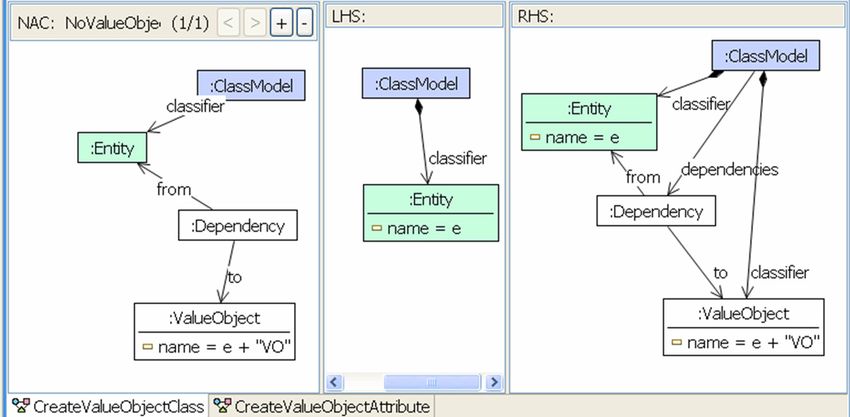
Mens et al., Model-Driven Software Refactoring

Model-driven software engineering.
In the realm of software engineering, we are witnessing an increasing
momentum towards the use of models for developing software systems.
This trend commonly referred to as model-driven software engineering,
emphases on models as the primary artifacts in all phases of software
development, from requirements analysis over system design to
implementation, deployment, verification and validation. This uniform
use of models promises to cope with the intrinsic complexity of
software-intensive systems by raising the level of abstraction, and by
hiding the accidental complexity of the underlying technology as much
as possible (Brooks, 1995). The use of models thus opens up new
possibilities for creating, analyzing, manipulating and formally reasoning
about systems at a high level of abstraction.
To reap all the benefits of model-driven engineering, it is essential to
install a sophisticated mechanism of model transformation, that enables a
wide range of different automated activities such as translation of models
(expressed in different modeling languages), generating code from
models, model refinement, model synthesis or model extraction, model
restructuring etc. To achieve this, languages, formalisms, techniques and
tools that support model transformation are needed. More importantly,
their impact on the quality and semantics of models needs to be better
understood.

Program refactoring.
Refactoring is a well-known technique to improve the quality of
software. Martin Fowler (1999) defines it as “A change made to the
internal structure of software to make it easier to understand and cheaper
to modify without changing its observable behavior”.
The research topic of refactoring has been studied extensively at the level
of programs (i.e., source code). As a result, all major integrated software
development environments provide some kind of automated support for
program refactoring.
As a simple example of a program refactoring, consider the refactoring
Extract Method, one of the more than 60 refactorings proposed by
Fowler. Essentially, it is applied to a method in which part of the method
body needs to be extracted into a new method that will be called by the
original one. The situation before this program refactoring on a piece of

                                             2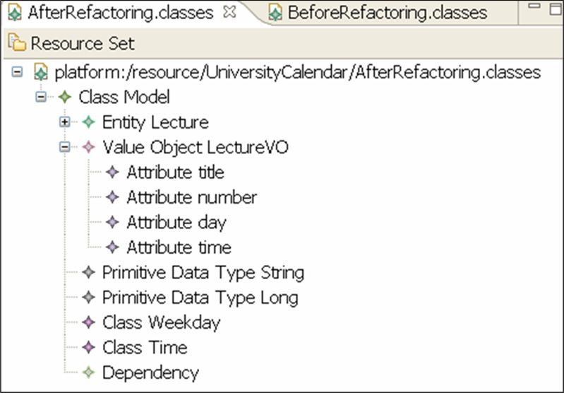
Mens et al., Model-Driven Software Refactoring

Java source code is shown in Figure 1, the situation after is shown in
Figure 2. The code lines that differ between both versions are marked
with an asterisk.
    protected LectureVO[] handleFindLecture
       (java.lang.String title, domain.Weekday day, domain.Time time)
       throws java.lang.Exception
*    { SearchCriteria c = new SearchCriteria();
*      c.setDay(day);
*      c.setTitle(title);
*      c.setTime(time);
       Collection coll =
        getLectureDao().findLecture(LectureDao.TRANSFORM_LECTUREVO,c);
       LectureVO[] lectures = new LectureVO[coll.size()];
       return (LectureVO[])coll.toArray(lectures); }

Figure 1: Java source code example before applying the Extract Method
program refactoring.
    protected LectureVO[] handleFindLecture
       (java.lang.String title, domain.Weekday day, domain.Time time)
       throws java.lang.Exception
*    { SearchCriteria c = this.initialise(title,day,time);
       Collection coll =
        getLectureDao().findLecture(LectureDao.TRANSFORM_LECTUREVO,c);
       LectureVO[] lectures = new LectureVO[coll.size()];
       return (LectureVO[])coll.toArray(lectures); }
* protected SearchCriteria initialise
*      (java.lang.String title, domain.Weekday day, domain.Time time)
*      throws java.lang.Exception
* { SearchCriteria c = new SearchCriteria();
*      c.setDay(day);
*      c.setTitle(title);
*      c.setTime(time);
*      return c; }

Figure 2: Java example after applying the Extract Method refactoring.

For program refactoring, a wide variety of formalisms has been proposed
to gain a deeper understanding, and to allow formal analysis. One of

                                             3
Mens et al., Model-Driven Software Refactoring

these formalisms is graph transformation theory (Mens et al., 2005). We
mention it here explicitly, as we will show later in this chapter how this
formalism can be applied to support model refactoring as well. It is,
however, not our goal to provide a detailed overview of existing work on
program refactoring here. For the interested reader, we refer to a detailed
survey of the state-of-the-art in this domain (Mens and Tourwé, 2004).

Model-driven software refactoring.
A natural next step seems to explore how the idea of refactoring may be
applied in a model-driven software development context. We will refer
to this combination as model-driven software refactoring and we will
explore the ramifications of this synergy in the current chapter.
One of the straightforward ways to address refactoring in a model-driven
context is by raising refactorings to the level of models, thereby
introducing the notion of model refactoring, which is a specific kind of
model transformation that allows us to improve the structure of the
model while preserving its quality characteristics. To the best of our
knowledge, Sunyé et al. (2001) were the first to apply the idea of
refactoring to models expressed in the Unified Modeling Language
(UML).
A simple yet illustrative example of a UML model refactoring is shown
in Figure 3. It depicts a class model in which two classes having
attributes of the same type have been identified. The model refactoring
consists of removing the redundancy by introducing an abstract super
class of both classes, and moving up the attribute to this new super class.

Figure 3: Example of a model refactoring on UML class diagrams.
The above example may look simple, but it should be seen in a more
general context, which makes dealing with model refactorings
considerable less trivial. Consider the scenario depicted in It clearly

                                             4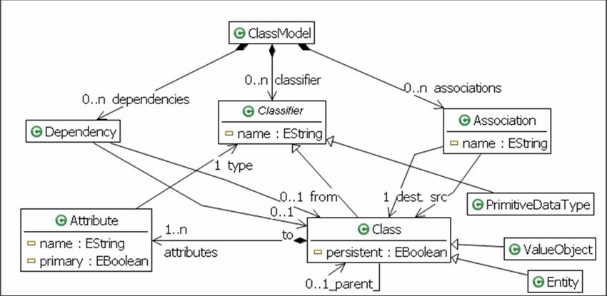
Mens et al., Model-Driven Software Refactoring

illustrates the potentially high impact a simple refactoring may have on
the software system. We assume that a model is built up from many
different views, typically using a variety of different diagrammatic
notations (e.g., class diagrams, state diagrams, use case diagrams,
interaction diagrams, activity diagrams, and many more). We also
assume that the model is used to generate code, while certain fragments
of the code still need to be implemented manually. Whenever we make a
change (in this case, a refactoring) to a single view or diagram in the
model (step 1 in Figure 4), it is likely that we need to synchronize all
related views, in order to avoid them becoming inconsistent (step 2 in
Figure 4) (Grundy et al., 1998). Next, since the model has been changed,
part of the code will need to be regenerated (step 3 in Figure 4). Finally,
the manually written code that depends on this generated code will need
to be adapted as well (step 4 in Figure 4).

Figure 4: A scenario for model-driven software refactoring.

                                             5
Mens et al., Model-Driven Software Refactoring

2. State-of-the-art in Model Refactoring
At the level of models, research on refactoring is still in its infancy. Little
research has been performed on model refactoring, and many open
questions remain that are worthy of further investigation. For example,
the relation between model refactoring and its effect on the model quality
remains a largely unanswered question. From a practical point of view,
only very few tools provide integrated support for model refactoring.
Also, the types of models for which refactoring is supported is very
limited.
In research literature, mainly UML models are considered as suitable
candidates for model refactoring (Sunyé et al., 2001) (Astels, 2002)
(Boger et al., 2002). In particular, refactoring of class models (e.g., UML
class diagrams) has been investigated by various researchers. The
advantage of such models is that they provide a representation that is
relatively close to the way object-oriented programs are structured. As
such, many of the refactorings known from object-oriented programming
(Fowler, 1999) can be ported to UML class diagrams as well. For
example, the refactoring shown in Figure 1 can also be considered as a
class diagram refactoring, since a new method is created that will be
visible in a class diagram. Of course, additional techniques are needed in
order to ensure traceability and consistency between class diagrams and
their corresponding source code when applying class diagram
refactorings (Bouden, 2006).
When it comes to reasoning about the behavior preservation properties of
class diagram refactorings, however, things become more difficult for
various reasons. The main problem is that class diagrams provide an
essentially structural description of the software architecture. Hence,
behavioral information has to be expressed in a different way, either by
resorting to OCL constraints, behavioral models (e.g., state diagrams or
interaction diagrams), or by program code.
With respect to refactoring of behavioral models, not much work is
available. We are only aware of a few approaches that address the
problem of refactoring state diagrams, and try to prove their behavior
preservation properties in a formal way. Van Kempen et al. (2005) use a
formalism based on CSP to describe statechart refactorings, and show
how this formalism can be used to verify that a refactoring effectively
preserves behavior. Pretschner and Prenninger (2006) provide a formal

                                             6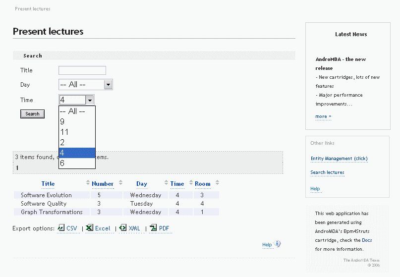
Mens et al., Model-Driven Software Refactoring

approach for refactoring state machines based on logical predicates and
tables. Integrating these ideas into tool support is left for future work.
Apart from some limitations imposed by the formalisms used, a more
general problem is that there is still no generally accepted formal
semantics for (UML) state diagrams. Many different interpretations exist
and, obviously, this has an important effect on how the behavior is
formally defined.
Though research on model refactoring is still in its infancy, a number of
formalisms have already been proposed to understand and explore model
refactoring. Most of these approaches suggest expressing model
refactoring in a declarative way. Van Der Straeten et al. (2004) propose
to use description logics; Van Der Straeten & D’Hondt (2006) suggest
the use of a forward-chaining logic reasoning engine to support
composite model refactorings. Gheyi et al. (2005) specify model
refactorings using Alloy, a formal object-oriented modeling language.
They use its formal verification system to specify and prove the
soundness of the transformations. Biermann et al. (2006) and Mens et al.
(2007) use graph transformation theory as an underlying foundation for
specifying model refactoring, and rely on the formal properties to reason
about and analyze these refactorings.
An important aspect of refactoring in a model-driven software
development context that is typically neglected in research literature is
how it interferes with code generation. Most contemporary tools for
model-driven software development allow generating a substantial part
of the source code automatically from the model, while other parts still
need to be specified manually (see Figure 4). This introduces the need to
synchronize between models and source code when either one of them
changes. How such synchronization can be achieved in presence of an
automated refactoring support is a question that has not been addressed
in detail in research literature. If a model is being refactored, how should
the corresponding source code be modified accordingly? Vice versa, if
source code is being refactored, how will the models be affected? These
are the kind of questions that will be addressed in this chapter. To this
extent, we will report on our experience with AndroMDA, a state-of-the-
art tool for model-driven software development based on UML.

                                             7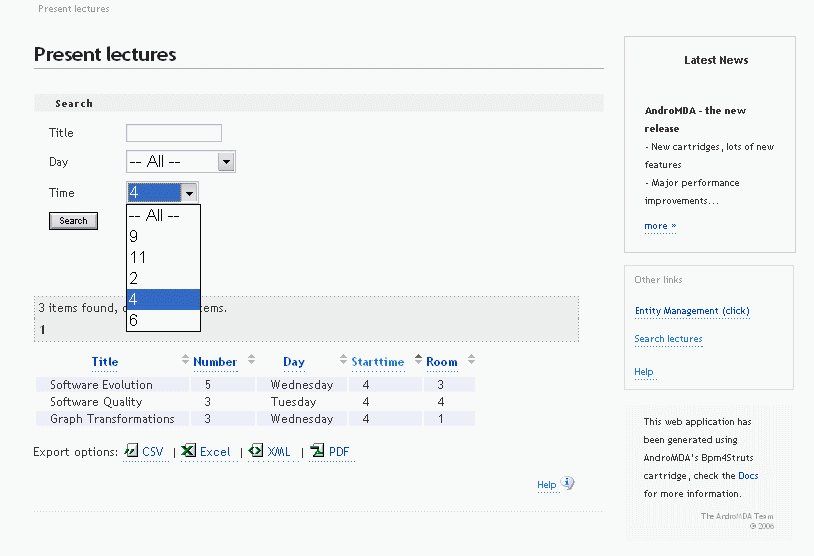
Mens et al., Model-Driven Software Refactoring

3. Motivating example: Model-driven development with AndroMDA
This section presents the model-driven development of a small web
application for a simple university calendar. We will develop this
calendar in two iteration steps using AndroMDA1. First the underlying
data model is designed and a web application with a default web
presentation is generated. Second, application-specific services and the
web presentation are developed with AndroMDA. This means that use
cases are defined and refined by activity diagrams that can use
controllers and services. The development is not hundred percent model-
driven, since service and controller bodies have to be coded by hand.
For both iteration steps, we first present the UML model using the
AndroMDA profile and then discuss a refactoring step useful in that
context.

3.1 Getting started with developing a university calendar using AndroMDA
One of the main tools for model-driven software development is
AndroMDA. Its transformation engine is structured by cartridges. A
number of pre-defined cartridges is already available realizing the
generation of web applications from UML models. We illustrate model-
driven software development based on AndroMDA by the example of a
very simple university calendar.
In principle, the model-driven development process of AndroMDA is
based on use cases. But in this initial example, we start with an even
simpler way of using AndroMDA. We just design the underlying data
model and AndroMDA generates a complete web application with a
default web presentation from that.
A web application generated by AndroMDA has a three-tier architecture
consisting of a service layer building up on a data base, controllers using
the services defined, and a web presentation. The underlying data model,
services and controllers are defined by an UML class diagram.
Additionally, visual object classes are modeled, which are used for
presenting data to the user, decoupled from the internal data model.

1
    http://galaxy.andromda.org

                                             8
Mens et al., Model-Driven Software Refactoring

Figure 5: Data model for a simple university calendar
An example of an AndroMDA class diagram is shown in Figure 5. It
depicts a simple data model for a university calendar. We can observe
that the basic entities are Rooms that can be occupied for giving a
Lecture or a Seminar. Based on this class diagram, AndroMDA can
generate a default web interface for managing lectures, seminars and
rooms. Users can add and delete instances, change attribute values and
perform searches. The webpage for managing lectures is shown in Figure
6.
The UML profiles used in connection with AndroMDA can be
considered as a domain-specific language, dedicated to the generation of
web applications. This is achieved by giving a specific semantics to
UML models by relying on that dedicated UML profiles. They extend
the semantics of the UML by introducing specific stereotypes, to which
additional constraints and tagged values are attached. For example, the
stereotype «Entity» attached to a class is used to represent a data entity
to be stored in a database. If, additionally, the «Manageable» stereotype
is used, it causes AndroMDA to generate a default web presentation for
managing the corresponding entities. The use of such manageable
entities has been illustrated in Figure 5.

                                             9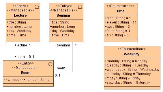
Mens et al., Model-Driven Software Refactoring

Figure 6: Webpage for managing lectures

3.2 First refactoring of the university calendar
Due to their compactness, large parts of AndroMDA UML models are
used for generating user interfaces. Thus, model refactorings in this
context are likely to cause changes in user interfaces as well. Following
Fowler (1999) in a strict sense, refactorings should not change the user
interface of software, since they are supposed to “preserve the observable
behavior”. This strict interpretation of refactoring, however, makes little
sense if applied in a model-driven software development context, due to
the side-effects that model refactorings may cause on the generated code,
especially user interfaces. Thus, Fowler’s definition of refactoring should
be interpreted in a more liberal way, in the sense that it should not
change the functionality offered by software. Modifications to the
usability of the software or to other non-functional properties (such as
interoperability, portability, reusability, adaptability and the like) should
be allowed, if the goal of these modifications is to improve the software
quality.
In the remainder of this section we will show a concrete refactoring on
our university calendar case study to clarify what refactoring can mean in
the context of model-driven development.

                                             10
Mens et al., Model-Driven Software Refactoring
Since «Entity» classes Lecture and Seminar contain several attributes
in common (see Figure 5), it would make sense to refactor this data
model by adding a new abstract superclass, called Course, and pulling
up all common attributes to this new class. The result of this refactoring
is shown in Figure 7.
Figure 7: Data model for a simple university calendar after having applied the
Pull Up Attribute refactoring
11Mens et al., Model-Driven Software Refactoring
Figure 8: Webpage for managing courses
Note that tagged value @andromda.hibernate.inheritance has to be
set to interface for restricting the management facilities for courses to
searching functionalities only.
When regenerating a web application from the refactored data model in
Figure 7, most of the web interface remains unaltered. But a new
webpage will appear for managing courses, as shown in Figure 8.
Because of the tagged value attached to Course, this webpage only offers
search functionality, but does not allow the addition or deletion of course
instances.
In the example explained in section 3.1, all application code is generated
from the model. Thus, refactoring the model alone appears to be
sufficient to refactor the whole software application. However, it should
be noted that, due to the refactoring applied to the model, the behavior
has been changed slightly, since AndroMDA has generated a new kind of
webpage.
12Mens et al., Model-Driven Software Refactoring
3.3 Developing application-specific use cases with AndroMDA
In this section, we will consider additional stereotypes and tagged values
in the AndroMDA UML profile, but only as far as we need them to
develop our example. For a complete overview of all available
stereotypes and how to use them we refer to the AndroMDA website.
«Service» is a class stereotype used to specify application-specific
services. These services typically use one or more entities that store the
data used by the services. For the model-driven development of a web
presentation, we extend the model by use cases that are refined by
activity diagrams. This model part describes the web presentation and its
usage of controllers based on services. The development is not hundred
percent model-driven, since service and controller bodies have to be
coded by hand.
To illustrate the development of specific web applications we reconsider
the university calendar and develop a specific use case diagram for
lectures (see Figure 9). Use case Search lectures has two stereotypes
being «FrontEndUseCase», which determines the use case to be visible
to the user in form of a webpage, and «FrontEndApplication», which
defines this use case to be the starting one.
Figure 9: Example of a use case model in AndroMDA
Use case Search lectures is refined by an activity diagram that
supports a search activity and the presentation of filtered lectures (see
Figure 10). Activity Search lectures is an internal activity that calls
the controller method showLectures(). Activity Present lectures
has stereotype «FrontEndView» implying that this activity models a
webpage. Both activities are connected by two transitions arranged in a
13Mens et al., Model-Driven Software Refactoring
cyclic way. After calling method showLectures() the result is
transferred to the webpage by signal show, which has the resulting value
object array as parameter. Signal search and its parameters are used to
model the web form for filtering the lectures.
Figure 10: Example of an activity diagram specifying the Search lectures use
case
The class model in Figure 5 is again used as data model. To show
lectures, a special value object class for lectures is used, which is
specified by stereotype «ValueObject» (see Figure 11). This makes
sense in terms of encapsulation (think of security, extensibility, etc.) and
corresponds to the layered model-view-controller approach. Necessary
information of the business layer is packaged into so-called "value
objects", which are used for the transfer to the presentation layer. Passing
real entity objects to the client may pose a security risk. Do you want the
client application to have access to the salary information inside the
Lecturer entity?
An attribute room of type String was added to LectureVO in order to
allow a connection to the unique number of the Room class. Since value
objects are used at the presentation layer, the types used are primitive
ones; entity types are not used in that layer. A dependency relation
between an entity and a value object is used to generate translation
methods from the entity to its corresponding value object. Moreover,
search criteria can be defined by a class of stereotype «Criteria».
14Mens et al., Model-Driven Software Refactoring
Figure 11: Value Object and Criteria classes
Method showLectures() that is called from activity Search lectures
in Figure 10, is defined in LectureController, a class that relies on
class LectureService. This class is stereotyped as «Service» and relies
on entities Lecture and Room (see Figure 12). However, the bodies of
service and controller methods cannot be modeled, but have to be coded
directly by hand. For example, the implementation of service method
findLecture()is shown in Figure 1. Because of special naming
conventions of AndroMDA it has to be named handleFindLecture().
The web application generated by AndroMDA from the complete model
given in the previous figures (together with manually written code parts)
produces the webpage shown in Figure 13. Please note that the names
used as page title, in the search form and for the buttons are generated
from the model.
15Mens et al., Model-Driven Software Refactoring
Figure 12: Service and controller classes
Figure 13: Webpage for searching lectures
16Mens et al., Model-Driven Software Refactoring
3.4 Further refactoring of the university calendar
As a second model refactoring2, we will discuss the renaming of attribute
time to starttime based on the model given in Section 3.3. We will
argue that this refactoring affects the usability of the generated software.
The refactoring is primarily performed on entity class Lecture, but since
there is a value object class LectureVO for that entity, the corresponding
value class attribute time has to be renamed into starttime, too (see
Figure 14). The same is true in SearchCriteria. Thus, the standard
refactoring method Rename Attribute becomes domain-specific and affects
several classes in this domain-specific context.
Figure 14: Value Object and Entity classes after renaming
Since the value object attribute is not used directly in other parts of the
model, the model does not have to be updated any further. But the hand-
written code (given in Figure 1) is affected, since accessor method
setTime() is no longer available after regenerating the code. Thus, it has
to be renamed as well, by calling method setStarttime() instead. After
2
This model refactoring is actually domain-specific, as will be discussed later in this
chapter.
17Mens et al., Model-Driven Software Refactoring
having performed this refactoring, the webpage for searching lectures has
been changed slightly. As a result, the usability is affected, though not
dramatically, since the column named “Time” of the presented table
presented has changed into “Starttime” (see Figure 15).
Figure 15: Webpage for searching lectures after renaming
Based on the analysis of both model refactorings carried out in this
section, we can derive the following important preliminary conclusions:
• Generic model refactorings need to be adapted and refined in order to
work properly in a domain-specific modeling language.
• Model refactorings may also affect, and require changes to the hand-
written source code.
• Model refactorings may change external qualities as perceived by the
user, such as usability aspects.
4. Challenges in model-driven software refactoring.
In this section, we will discuss some important challenges in model
refactoring that have to do with the relation between model refactoring
and model quality. It is not our ambition to solve all these challenges in
18Mens et al., Model-Driven Software Refactoring
the current chapter. In Sections 5 and 6 we will therefore only focus on
those challenges that we consider being most urgent and most important
and we will exemplify our proposed solution using the case study
introduced in the previous section.
Model quality.
A first challenge is to provide a precise definition of model quality. A
model can have many different non-functional properties or quality
characteristics that may be desirable (some examples are: usability,
readability, performance and adaptability). It remains an open challenge
to identify which qualities are necessary and sufficient for which type of
stakeholder, as well as how to specify these qualities formally, and how
to relate them to one another.
Since the main goal of refactoring is to improve certain aspects of the
software quality, we need means to assess this quality at the model level
in an objective way. On the one hand, this will allow software modelers
to identify which parts of the model contain symptoms of poor quality,
and are hence potential candidates for model refactoring. On the other
hand, quality assessment techniques can be used to verify to which extent
model refactorings actually improve the model quality.
One of the ways to assess model quality is by resorting to what we will
call model smells. These are the model-level equivalent of bad smells, a
term originally coined by Kent Beck in (Fowler, 1999) to refer to
structures in the code that suggest opportunities for refactoring. Typical
model smells have to do with redundancies, ambiguities, inconsistencies,
incompleteness, non-adherence to design conventions or standards, abuse
of the modeling notation, and so on. A challenge here is to come up with
a comprehensive and commonly accepted list of model smells, as well as
tool support to detect such smells in an automated way. What is also
needed is a good understanding of the relation between model smells and
model refactoring, in order to be able to suggest, for any given model
smell, appropriate model refactorings that can remove this smell.
A second way to assess and control model quality is by resorting to
model metrics. In analogy with software metrics (Fenton and Pfleeger,
1997) they are used to measure and quantify desirable aspects of models.
It remains an open question, however, how to define model metrics in
such a way that they correlate well with external model quality
19Mens et al., Model-Driven Software Refactoring
characteristics. Another important issue is to explore the relation between
model metrics and model refactoring, and in particular to assess to which
extent model refactorings affect metric values. These issues have been
addressed by (Demeyer et al., 2000) (Du Bois, 2006) (Tahvildari &
Kontogiannis, 2004) though mainly at code level.
A final way to improve model quality is by introducing design patterns,
which are proven solutions to recurring problems (Gamma et al., 1994).
At code level, Kerievsky (2004) explored the relation between
refactorings and design patterns. It remains to be seen how similar results
may be achieved at the level of models.
Kamthan (2004) provided a quality framework for UML models. It
systematically studies the quality goals, how to assess them, as well as
techniques for improving the quality, similar to the ones discussed above.
Model synchronization.
With respect to model refactoring, one of the key questions is how it
actually differs from program refactoring. Can the same ideas,
techniques and even tools used for program refactoring be ported to the
level of models? If not, what is it precisely that makes them different?
One answer to this question is that models are typically built up from
different views, using different types of diagrams, that all need to be kept
consistent. This in contrast to programs, that are often (though not
always) expressed within a single programming language.3
Perhaps a more important difference is that models are abstract artifacts
whose main purpose is to facilitate software development by generating a
large portion of the source code that would otherwise need to be written
manually. However, 100% full code generation is unfeasible in practice
for most application domains. The additional challenge therefore consists
in the need to synchronize and maintain consistency between models and
their corresponding program code, especially when part of this program
code has been specified or modified manually. In the context of model
3
Of course, programs also need to be synchronised with related software artefacts such
as databases, user interfaces, test suites and so on. Each of these kinds of artefacts may
have been expressed using a different language.
20Mens et al., Model-Driven Software Refactoring
transformation, this implies that automated model refactorings (or other
transformations) may need to be supplemented with code-level
transformations in order to ensure overall consistency. Vice versa,
program refactorings may need to be supplemented with model-level
transformations to ensure their consistency.
Though no general solutions exist yet, the problem of model
synchronization and model consistency maintenance is well known in
literature. For example, (Van Gorp et al., 2003) discuss the problem of
keeping the UML models consistent with its corresponding program
code. (Correa & Werner, 2004) explain how OCL constraints need to be
kept in sync when the class diagrams are refactored and vice versa.
Egyed (2006) proposes an incremental approach to model consistency
checking that scales up to large industrial models. Liu et al. (2002) and
Van Der Straeten & D’Hondt (2006) rely on a rule-based approach for
detecting and resolving UML model inconsistencies, respectively. Van
Der Straeten et al. (2003) bear on the formalism of description logics to
achieve the same goal. Mens et al. (2006) propose to resolve
inconsistencies in an incremental fashion by relying on the formalism of
graph transformation. Grundy et al. (1998) report on how tool support
can be provided for managing inconsistencies in a software system
composed of multiple views. Goedicke et al. (1999) address the same
problem by relying on the formalism of distributed graph transformation.
Behavior preservation.
Another important challenge of model refactoring has to do with
behavior preservation. By definition, a model refactoring is supposed to
preserve the observable behavior of the model it is transforming. In order
to achieve this, we need a precise definition of “behavior” in general, and
for models in particular. In addition, we need formalisms that allow us to
specify behavioral invariants, i.e., properties that need to be preserved by
the refactoring. The formalism should then verify which of these
invariants are preserved by the model refactoring. Although formal
research on behavior preservation is still in its infancy, in Section 2 we
already pointed to a few approaches that carried out initial research in
this direction. Another approach that is worthwhile mentioning is the
work by Gheyi et al. (2005). They suggest specifying model refactorings
in Alloy, an object-oriented modeling language used for formal
21Mens et al., Model-Driven Software Refactoring
specification. It can be used to prove semantics-preserving properties of
model refactorings.
A more pragmatic way to ensure that the behavior remains preserved by
a refactoring is by resorting to testing techniques. Many researchers have
looked at how to combine the ideas of testing with model-driven
engineering (Brottier et al., 2006) (Mottu et al., 2006). Test-driven
development is suggested by the agile methods community as good
practice for writing high-quality software. In combination with
refactoring, it implies that before and after each refactoring step, tests are
executed to ensure that the behavior remains unaltered.
Domain-specific modeling.
A final challenge is the need to define model refactorings in domain-
specific extensions of the UML (such as AndroMDA), or even in
dedicated domain-specific modeling languages. These refactorings
should be expressible in a generic yet customizable way. Indeed, given
the large number of very diverse domain-specific languages, it is not
feasible, nor desirable, to develop dedicated tools for all of them from
scratch.
Zhang et al. (2004) therefore proposed a generic model transformation
engine and used it to specify refactorings for domain-specific models.
Their tool is implemented in the Generic Modeling Environment (GME),
a UML-based meta-modeling environment. A model refactoring browser
has been implemented as a GME plug-in. Their tool enables the
automation and user-defined customization of model refactorings using
ECL (Embedded Constraint Language), an extension of the declarative
OCL language with imperative constructs to support model
transformation. As an example of the expressiveness of their approach,
they illustrated how it can be applied to class diagrams, state diagrams
and Petri nets. The solution that we will explore later in this chapter is
related, in the sense that we will propose a generic approach for UML-
based model refactoring based on graph transformation concepts.
In general, the main challenge remains to determine, for a given domain-
specific modeling language, which transformations can be considered as
meaningful refactorings. On the one hand, they will need to preserve
some notion of “behavior” and, on the other hand, they need to improve
some quality aspect. These notions of behavior and quality can differ
22Mens et al., Model-Driven Software Refactoring
widely depending on the domain under study. For domains that do not
refer to software (e.g., business domains, technical domains, etc.) it is
much harder to come to a meaningful definition of behavior, implying
that the notion of refactoring would become much harder to define in that
context.
Analyzing model refactorings.
Even more advanced support for model refactorings can be envisaged if
we have a precise means to analyze and understand the relationships
between refactorings. This will enable us to build up complex
refactorings from simpler ones; to detect whether refactorings are
mutually exclusive, in the sense that they are not jointly applicable and to
analyze causal dependencies between refactorings. These techniques
have been explored in detail by Mens et al. (2007), and promise to offer
more guidance to the developer on what is the most appropriate
refactoring to apply in which context. A short introduction to this line of
research will be given in Section 6.
5. Motivating example revisited
In Section 3 two concrete model refactorings have been applied to
AndroMDA models: pulling up an attribute into a new superclass and
renaming an entity. In this section, we explore some more refactorings
for AndroMDA models.4 We start by considering a set of “standard”
model refactorings widely used to restructure class diagrams. As it will
turn out, most of these refactorings have side-effects due to constraints
imposed by AndroMDA’s code generator. Therefore, these model
refactorings need to be customized to take into account more domain-
specific information. Next to these “standard” refactorings, we will also
discuss entirely new “domain-specific” refactorings for AndroMDA
models.
In the following, we will take a slightly broader view, and we discuss
three categories of model transformations as follows:
(1) model refactorings that do not affect the user interface at all;
4
It is not our goal to be complete here.
23Mens et al., Model-Driven Software Refactoring
(2) model refactorings that do affect the user interface with respect to the
usability, but that do not affect what the user can do with the application;
and
(3) model transformations that also affect the actual
behavior/functionality of the application.
The latter category does not contain refactorings in the strict sense of the
word, but it is nevertheless useful and necessary to deal with them. For
example, it could be the case that what is perceived as a normal
refactoring will actually extend the behavior as a side effect of the code
generation process.
Pull up Attribute.
When pulling up an attribute to a super class, as explained in Section 3.2,
the code generator will automatically generate a new webpage
corresponding to this super class, with search functionality for each
manageable entity. Thus, this model transformation belongs to category
(3).
Rename.
The refactoring example in Section 3.4 is concerned with renaming an
attribute of an entity class. This refactoring affects the user interface, if
the entity is manageable. In this case, one of the columns in the table of
the webpage has been renamed. Furthermore, in case that the entity class
comes along with a value object class that is derived from the entity
class, a renaming of an entity attribute has to be accompanied by a
renaming of the corresponding attribute in its value object class. If, in
addition, this value object attribute is used in some activity diagram, the
name has to be adapted there as well. Furthermore, this value object
attribute can occur in hand-written code, which implies that renaming
has to be performed also in that part of the code.
A similar situation would arise if we renamed the entity class itself, as it
would be reflected by a change in the title of the corresponding webpage
for manageable entities. In case that the renamed entity class comes
along with a value object class whose name is derived from the entity
class name (e.g., in Figure 14, “LectureVO” is derived from “Lecture”
by suffixing “VO”), renaming has to be accompanied by a renaming of its
corresponding value object class. Furthermore, the renaming has to be
24Mens et al., Model-Driven Software Refactoring
propagated as discussed for attributes. In all cases presented, although
the user interface changes slightly, the functionality of the application is
not affected. Hence, these refactorings belong to category (2).
Similar to entities, use cases can be renamed as well. This might have an
effect on activity diagrams, since AndroMDA supports the connection of
several activity diagrams via use case names. For example, an end
activity of one activity diagram may be named as a use case, which
means that the control flow would continue at the start activity of the
corresponding activity diagram. In the generated web applications, use
cases are listed on the right-hand side of each webpage. Again, a
renamed use case would change the usability of the web application, but
not its functionality, so the refactoring belongs to category (2).
In summary, we see that renaming in AndroMDA may have a high
impact. Due to the fact that the code generator automatically produces
new types of elements based on the names of existing elements, a
seemingly simple change (in casu renaming) will propagate to many
different places. A tool that would implement this model refactoring
would therefore need to take these issues into account to ensure that the
renaming does not lead to an inconsistent model or code. Furthermore,
because the changes affect hand-written code, the refactoring may
require a certain amount of user interaction.
Create Value Object.
A domain-specific refactoring for AndroMDA models is the creation of
value objects for entities. An example is visually represented in Figure
16. Given a class with stereotype «Entity» (for example, class
Lecture), a new class with stereotype «Value Object» is created and
the entity class becomes dependent on this new class. The value object
class is named after its entity class followed by suffix “VO” (for example,
value object class LectureVO). The entity attributes are copied to the
value object class, keeping names and types, by default. If internal
information should be hidden from the client, the corresponding attribute
would not be copied. This refactoring belongs to category (1) and does
not affect any other part of the model, since the value object class is only
created without being used yet.
25Mens et al., Model-Driven Software Refactoring
Figure 16: Example of the domain-specific model refactoring CreateValueOb-
ject.
Merge Services.
Another domain-specific model refactoring is Merge Services. It takes
two «Service» classes and merges them as well as all their incoming
and outgoing dependencies. Consider the following example where both
a LectureService and RoomService exist (see Figure 17). If we do not
consider remote services and have only one controller class, it does not
make sense to have two service classes. Therefore, both should be
merged into LectureService. After refactoring, the controller class will
have only one outgoing dependency. As a result, the hand-written code
for the controller method will be affected. Nevertheless, this
restructuring will not modify the external behavior, so users of the
generated web application will not notice any change. Hence, this
refactoring falls into category (1).
26Mens et al., Model-Driven Software Refactoring
Figure 17: Service classes LectureService and RoomService with
dependencies
Split Activity.
The front-end of a web application is modeled by use cases and activity
diagrams. A refactoring like the splitting of activities into two
consecutive ones, linked by a transition, can directly affect the web
presentation. If the original activity was a «FrontEndView», the
corresponding webpage is split into two pages. If an internal activity was
split, this refactoring has to be accompanied by a splitting of the
corresponding controller method called. In the first case, the refactoring
belongs to category (2), in the second case it belongs to category (1).
Extract Method.
Extract Method is a refactoring from the standard catalogue established
by Fowler. In the context of model-driven development, and AndroMDA
in particular, it can have new effects. Consider the scenario in Figure 19.
First, we perform the extract method refactoring to the hand-written
code, as illustrated in Figure 2 where a method, called initialise(), is
extracted from a given service method handleFindLecture. To reflect
this change at model level, we modify the class diagram by adding the
extracted method to the class LectureService as well (see Figure 18).
27Mens et al., Model-Driven Software Refactoring
Consequently, the code generator will generate extra code for this
method, which requires the manually written code to be adapted to make
it consistent again. In particular, method initialise() needs to be
renamed into handleInitialise(), because this is the convention used
by the code generator: all service methods need to be prefixed with
"handle" at source code level. We can use this knowledge to constrain
the Extract Method refactoring to make it domain-specific: When
extracting a method, the name that the user needs to provide for the
extracted method needs to follow the naming conventions imposed by
the code generator. Not doing so will cause the precondition of the
refactoring to fail.
Figure 18: Changes to the class diagram as a result of applying the Extract
Method program refactoring (see Figure 2).
The above scenario is generalized and visualized in Figure 19. It shows
how a refactoring at source code level (step 1) may require
synchronization of the corresponding model (step 2) which, after
regenerating the code (step 3) involves another modification to the hand-
written part of the code (step 4). The last step is not needed, if the user
obeys the naming convention for the new method as discussed above.
28Mens et al., Model-Driven Software Refactoring
Figure 19: Another scenario of model-driven software refactoring, initiated by
a refactoring of the hand-written source code.
6. Specifying and analyzing model refactorings
In Section 5, the important challenge of domain-independent support for
model refactoring was discussed. A possible formalism that can be used
to specify and also analyze refactorings is the theory of graph
transformation (Ehrig et al. 2006). Compared to other approaches it has
a number of advantages: it allows one to specify program refactorings
and model refactorings for various languages in a uniform and generic
way, by representing the software artifact under consideration as a graph,
and by specifying the refactorings as graph transformation rules. In
addition, one can benefit from the formal properties of graph
transformation theory to reason about refactoring in a formal way. For
example, properties such as termination, composition, parallel
dependencies, and sequential dependencies can be analyzed.
Since the Eclipse Modeling Framework (EMF) has become a key
reference for model specification in the world of model-driven
development, we rely our approach to model refactoring on EMF model
transformation. This approach is presented in Section 6.1. To perform a
formal analysis of EMF transformations we translate them to graph
29Mens et al., Model-Driven Software Refactoring
transformations, which is possible under certain circumstances. In
Section 6.2, a conflict and dependency analysis of model refactorings is
presented, assuming that the model refactorings are defined by graph
transformation rules.
6.1 Technical solution
From a technical point of view, we will discuss how to implement and
execute model refactorings. In particular, we will consider how to realize
model refactoring within the Eclipse Modeling Framework (EMF). As a
prerequisite, a specification of the underlying modeling language is
needed, which will be given by a meta-model. Figure 20 shows an EMF
model that represents a simplified extract of the AndroMDA meta-
model. Figure 21 shows an instance of this EMF model for the entity
class Lecture of the simple university calendar.
Figure 20: Extract of AndroMDA meta-model as EMF model.
30Mens et al., Model-Driven Software Refactoring
Figure 21: Entity class Lecture with attributes in abstract syntax as EMF
model instance.
Biermann et al. (2006) explain in detail how EMF model refactoring can
be expressed by EMF model transformation. This kind of model
transformation is specified by rules and is performed in-place, i.e., the
current model is directly changed and not copied. Each transformation
rule consists of a left-hand side (LHS), indicating the preconditions of
the transformation, a right-hand side (RHS), formulating the post
conditions of the transformations, and optional negative application
conditions (NAC), defining forbidden structures that prevent application
of the transformation rule. Objects that are checked as precondition
preserved during a transformation are indicated by colors. Object nodes
of the same color present one and the same object in different parts of a
rule. While attributes in the LHS may have constant values or rule
variables only, they are allowed to carry Java expressions in the RHS,
too. The same variable at different places in the rules means the same
value at all places. In the following, we use this approach to EMF model
transformation for specifying UML model refactorings.
In Figure 22 and Figure 23, two model transformation rules are shown,
which both are needed to perform refactoring Create Value Object
explained in Figure 16 of Section 5. Rule CreateValueObjectClass is
applied once, creating a new value object class and a dependency of the
entity class on this new class. A class model with an entity class is
needed to create a value object class and a dependency in between. The
name of this new value object class is constructed by taking the entity
31Mens et al., Model-Driven Software Refactoring
class name e and adding suffix "VO". This rule is applied only if a value
object class of this name has not already been created.
Figure 22: EMF model transformation rule CreateValueObjectClass for
refactoring method Create Value Object.
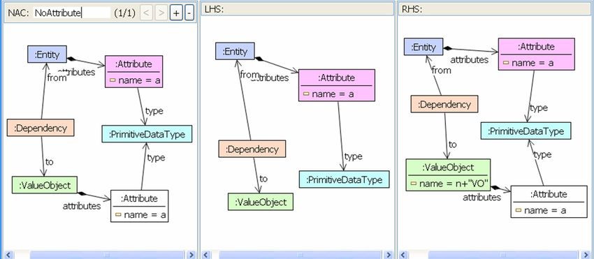
Thereafter, rule CreateValueObjectAttribute is applied for each of the
attributes of the entity class that should occur also in the value object
class. Each time it is applied, it copies an attribute that has not yet been
copied into the value object.
Figure 23: EMF model transformation rule CreateValueObjectAttribute for
refactoring method Create Value Object.
Applying rule CreateValueObjectClass once and rule CreateValueOb-
jectAttribute as often as entity class Lecture has attributes (i.e., four
32Mens et al., Model-Driven Software Refactoring
times in this case) to the EMF model instance in Figure 21, we obtain the
EMF model instance in Figure 24.
Figure 24: Entity class Lecture with value object class LectureVO in
abstract syntax as EMF model instance.
To open up the possibility for analyzing EMF model refactorings, we
translate them to graph transformations. In this way, the formal analysis
for graph transformation becomes available for EMF model refactoring.
Although EMF models show a graph-like structure and can be
transformed similarly to graphs, there is an important difference between
both. In contrast to graphs, EMF models have a distinguished tree
structure that is defined by the containment relation between their
classes. Each class can be contained in at most one other class. Since an
EMF model may have non-containment references in addition, the
following question arises: What if a class, which is transitively contained
in a root class, has non-containment references to other classes not
transitively contained in some root class? In this case we consider the
EMF model to be inconsistent.
A transformation can invalidate an EMF model, if its rule deletes one or
more objects. To ensure consistent transformations only, rules that delete
objects or containment links or redirect them, have to be equipped with
additional NACs.
33Mens et al., Model-Driven Software Refactoring
6.2 Formal solution
As an illustration of how refactoring dependency analysis may increase
the understanding of refactoring, consider the following scenario.
Assume that a software developer wants to know which refactoring rules
need to be applied in order to restructure a software system. Typically,
many different refactoring rules may be applicable, and it is not easy to
find out what would be the most optimal way to apply these rules. Joint
application of some refactoring rules may not be possible due to parallel
dependencies between them, and some refactoring rules may sequentially
depend on other ones. Graph transformation theory allows us to compute
such dependencies by relying on the idea of critical pair analysis. The
general-purpose graph transformation tool AGG5 provides an algorithm
implementing this analysis.
Figure 25: Sequential dependencies computed by AGG for a representative set
of refactorings implemented as graph transformations.
Figure 25 gives an example of all sequential dependencies that have
been computed between a representative, yet simplified, subset of
refactorings expressed as graph transformation rules. For example, we
see that there is a sequential dependency between the CreateSuperclass
refactoring and the PullUpVariable refactoring. CreateSuperclass inserts
a new intermediate superclass (identified by node number 2) in between
a class (node 1) and its old superclass (node 3). PullUpVariable moves a
5
http://tfs.cs.tu-berlin.de/agg
34Mens et al., Model-Driven Software Refactoring
variable contained in a class up to its superclass. The dependency
between both transformation rules, as computed by AGG, is visualized in
Figure 26. The effect of applying CreateSuperclass before
PullUpVariable will be that the variable will be pulled up to the newly
introduced intermediate superclass instead of the old one. As such, there
is a sequential dependency between both refactoring rules. It is even the
case, in this example, that the application of both refactorings in a
different order will produce a different result.
Figure 26: Example of a sequential dependency between the CreateSuperclass
and the PullUpVariable refactoring.
For a more detailed discussion of how critical pair analysis can be
used to reason about refactoring dependencies, we refer to (Mens et al.,
2007) that provides a detailed account on these issues.
6.3 Related Work
Various authors have proposed to use some kind of rule-based approach
to specify model refactorings, so it appears to be a natural choice:
Grunske et al. (2005) show an example in Fujaba6 of how model
refactoring may be achieved using graph transformation based on story-
driven modeling. Bottoni et al. (2005) use distributed graph
transformation concepts to specify coherent refactorings of several
software artifacts, especially UML models and Java programs. Both
kinds of artifacts are represented by their abstract syntax structures.
6
http://www.fujaba.de
35Mens et al., Model-Driven Software Refactoring
Synchronized rules are defined to specify not only refactoring on models
and programs separately, but to update also the correlation between
different model parts and program. Synchronized rules are applied in
parallel to keep coherence between model and program. Considering the
special case where exactly two parts (one model diagram and the
program or two model diagrams) are related, the triple graph grammar
(TGG) approach by Schürr et al. (Schürr 1994, Königs & Schürr 2006)
could also be used. Originally formulated for graphs, TGGs are also
defined and performed on the basis of MOF models by the modeling
environment MOFLON7.
(Porres, 2003) uses the transformation language SMW to specify model
refactorings. This script language is also rule-based and resembles the
Object Constraint Language (OCL). SMW is oriented at OCL for
querying patterns, but also provides basic operations to realize
transformations. A prototypical refactoring tool for UML models has
been implemented based on SMW.
Van Der Straeten and D’Hondt (2006) suggest using a rule-based
approach to apply model refactorings, based on an underlying
inconsistency detection and resolution mechanism implemented in the
description logics engine RACER8.
We decided to specify model refactorings based on EMF model
transformation, since EMF is developing to a standard format for models
and to be compatible with upcoming UML CASE tools based on EMF.
Moreover, our approach opens up the possibility for analyzing model
refactorings, since EMF model transformations can be translated to
algebraic graph transformations.
7. Summary
Software complexity is constantly increasing, and can only be tamed by
raising the level of abstraction from code to models. With the model-
driven software engineering paradigm, automated code generation
techniques can be used to hide the accidental complexity of the
7
http://www.moflon.org
8
http://www.racer-systems.com
36You can also read