INSTRUCTION MANUAL UNIVERSAL FIELDBUS-GATEWAY UNIGATE CL - ETHERNET/IP 2PORT - DEUTSCHMANN AUTOMATION GMBH & CO. KG WWW.DEUTSCHMANN.COM | ...
←
→
Page content transcription
If your browser does not render page correctly, please read the page content below
Instruction Manual
Universal Fieldbus-Gateway
UNIGATE® CL - EtherNet/IP 2Port
Deutschmann Automation GmbH & Co. KG
www.deutschmann.com | wiki.deutschmann.de
Manual Art.-No.: V3898E
Deutschmann Automation GmbH & Co. KG

1   Information on CE marking of the module . . . . . . . . . . . . . . . 9
    1.1    EU Directive EMC . . . . .              .   .   .   .   .   .   .   .   .   .   .       .       .       .       .   .   .   .   .   .   .       .       .       .       .   9
    1.2    Scope of application . . . .            .   .   .   .   .   .   .   .   .   .   .       .       .       .       .   .   .   .   .   .   .       .       .       .       .   9
    1.3    Note installation guidelines            .   .   .   .   .   .   .   .   .   .   .       .       .       .       .   .   .   .   .   .   .       .       .       .       .   9
    1.4    Installation of the unit . . .          .   .   .   .   .   .   .   .   .   .   .       .       .       .       .   .   .   .   .   .   .       .       .       .       .   9
    1.5    Working on switch cabinets              .   .   .   .   .   .   .   .   .   .   .       .       .       .       .   .   .   .   .   .   .       .       .       .       .   9
2   Information for the machine manufacturers                                              . . . . . . . . . . . . . 10
    2.1    Introduction . . . . . . . . . . . . . . . . . . . . . . . . . . . . . . . . 10
    2.2    EU Machinery Directive . . . . . . . . . . . . . . . . . . . . . . . . . . 10
3   Introduction . . . . . . . . . . . . . . . . . . . . . . . . . . . . . . . .11
    3.1    UNIGATE® CL software flow-chart . . . . . . . . . . . . . . . . . . . . 12
    3.2    UNIGATE® application diagram . . . . . . . . . . . . . . . . . . . . . . 13
4   Operation modes of the Gateway . . . . . . . . . . . . . . . . . . . 14
    4.1    Configuration mode (config mode) . . . . . . . . . . . . . . . . . . . . 14
    4.2    Test mode . . . . . . . . . . . . . . . . . . . . . . . . . . . . . . . . . 14
    4.3    Data exchange mode . . . . . . . . . . . . . . . . . . . . . . . . . . . 14
5   RS-interface . . . . . . . . . . . . . . . . . . . . . . . . . . . . . . . 15
    5.1    RS-interfaces at the UNIGATE® CL . . . . . . . . . . . . . . . . . . . . 15
    5.2    Buffer sizes at the UNIGATE® CL . . . . . . . . . . . . . . . . . . . . . 15
    5.3    Framing Check . . . . . . . . . . . . . . . . . . . . . . . . . . . . . . 15
6   SSI-interface . . . . . . . . . . . . . . . . . . . . . . . . . . . . . . . 16
    6.1    Initiation of the SSI-interface . . . . . . . . . . . . . . . . . . . . . . . 16
    6.2    Parameter . . . . . . . . . . . . . . . . . . . . . . . . . . . . . . . . . 16
       6.2.1   Resolution . . . . . . . . . . . . . . . . . . . . .                            .       .       .       .   .   .   .   .   .   .   .   .       .       .       .   16
       6.2.2   SSI Encoder Type . . . . . . . . . . . . . . . .                                .       .       .       .   .   .   .   .   .   .   .   .       .       .       .   16
       6.2.3   Parameter sample frequency (Clock stretch) . . .                                .       .       .       .   .   .   .   .   .   .   .   .       .       .       .   16
       6.2.4   Parameter Encoder monitoring (Check Encoder) .                                  .       .       .       .   .   .   .   .   .   .   .   .       .       .       .   17
    6.3    Hardware-wiring . . . . . . . . . . . . . . . . . . . . . . . . . . . . . . 17
7   The Debug-interface . . . . . . . . . . . . . . . . . . . . . . . . . . 18
    7.1    Overview of the Debug-interface . . . . . . . . .                                               .       .       .   .   .   .   .   .   .       .       .       .       18
    7.2    Starting in the Debug-mode . . . . . . . . . . . .                                              .       .       .   .   .   .   .   .   .       .       .       .       18
    7.3    Communication parameter for the Debug-interface                                                 .       .       .   .   .   .   .   .   .       .       .       .       18
    7.4    Possibilities with the Debug-interface . . . . . . .                                            .       .       .   .   .   .   .   .   .       .       .       .       18
    7.5    Commands of the Debug-interface . . . . . . . .                                                 .       .       .   .   .   .   .   .   .       .       .       .       18
8   Mode of operation of the system                            . . . . . . . . . . . . . . . . . . . 19
    8.1    General explanation .       .   .   .   .   .   .   .   .   .   .   .   .   .   .       .       .       .       .   .   .   .   .   .   .       .       .       .       19
    8.2    Interfaces . . . . . .      .   .   .   .   .   .   .   .   .   .   .   .   .   .       .       .       .       .   .   .   .   .   .   .       .       .       .       19
    8.3    Data exchange . . .         .   .   .   .   .   .   .   .   .   .   .   .   .   .       .       .       .       .   .   .   .   .   .   .       .       .       .       19
    8.4    Possible data lengths       .   .   .   .   .   .   .   .   .   .   .   .   .   .       .       .       .       .   .   .   .   .   .   .       .       .       .       19
    8.5    Startup phase . . . .       .   .   .   .   .   .   .   .   .   .   .   .   .   .       .       .       .       .   .   .   .   .   .   .       .       .       .       19
9   Generating a Script . . . . . . . . . . . . . . . . . . . . . . . . . . . 20
    9.1    What is a Script? . . . . . . . . . . .                         .   .   .   .   .       .       .       .       .   .   .   .   .   .   .       .       .       .       20
    9.2    Memory efficiency of the programs . .                           .   .   .   .   .       .       .       .       .   .   .   .   .   .   .       .       .       .       20
    9.3    What can you do with a Script device?                           .   .   .   .   .       .       .       .       .   .   .   .   .   .   .       .       .       .       20
    9.4    Independence of buses . . . . . . . .                           .   .   .   .   .       .       .       .       .   .   .   .   .   .   .       .       .       .       20

 12.1.21         Instruction manual UNIGATE® CL - EtherNet/IP 2Port V. 1.9                                                                                                             4
Deutschmann Automation GmbH & Co. KG
9.5 Further settings at the Gateway . . . . . . . . . . . . . . . . . . . . . . 20
9.6 The use of the Protocol Developer . . . . . . . . . . . . . . . . . . . . 21
10 Implemented protocols in UNIGATE® CL with Universal Script . . . 22
10.1 Protocol: Transparent . . . . . . . . . . . . . . . . . . . . . . . . . . . 22
10.1.1 Data structure . . . . . . . . . . . . . . . . . . . . . . . . . . . . . . . . . . 22
10.2 Protocol: Universal 232 . . . . . . . . . . . . . . . . . . . . . . . . . . 22
10.2.1 Data structure . . . . . . . . . . . . . . . . . . . . . . . . . . . . . . . . . . 22
10.2.2 Fieldbus parameters . . . . . . . . . . . . . . . . . . . . . . . . . . . . . . . 22
10.2.3 RS232 parameter table . . . . . . . . . . . . . . . . . . . . . . . . . . . . . 23
10.2.3.1 Start character (232 Start character) . . . . . . . . . . . . . . . . . . . . . . . . . 23
10.2.3.2 Length 232 (232 Length) . . . . . . . . . . . . . . . . . . . . . . . . . . . . . . . 23
10.2.3.3 Timeout . . . . . . . . . . . . . . . . . . . . . . . . . . . . . . . . . . . . . . . . 23
10.2.3.4 End character (232 End character) . . . . . . . . . . . . . . . . . . . . . . . . . . 23
10.2.4 Communication sequence . . . . . . . . . . . . . . . . . . . . . . . . . . . . 23
10.3 Protocol: 3964(R) . . . . . . . . . . . . . . . . . . . . . . . . . . . . . 24
10.3.1 Data structure 3964R . . . . . . . . . . . . . . . . . . . . . . . . . . . . . . 24
10.3.2 Protocol definitions . . . . . . . . . . . . . . . . . . . . . . . . . . . . . . . . 24
10.3.3 Data communication . . . . . . . . . . . . . . . . . . . . . . . . . . . . . . . 24
10.3.3.1 Initiation of data communication by the low-priority user . . . . . . . . . . . . . . . 24
10.3.3.2 Conflicts . . . . . . . . . . . . . . . . . . . . . . . . . . . . . . . . . . . . . . . . 24
10.3.3.3 Timeout times . . . . . . . . . . . . . . . . . . . . . . . . . . . . . . . . . . . . . 24
10.3.3.4 Retries . . . . . . . . . . . . . . . . . . . . . . . . . . . . . . . . . . . . . . . . . 25
10.3.3.5 Initiation of data communication by the high-priority user . . . . . . . . . . . . . . . 25
10.3.4 Protocol type 3964 . . . . . . . . . . . . . . . . . . . . . . . . . . . . . . . . 25
10.4 Protocol: MODBUS-RTU . . . . . . . . . . . . . . . . . . . . . . . . . 25
10.4.1 Notes . . . . . . . . . . . . . . . . . . . . . . . . . . . . . . . . . . . . . . . 25
10.4.2 UNIGATE® as MODBUS-Master . . . . . . . . . . . . . . . . . . . . . . . . 25
10.4.2.1 Preparation . . . . . . . . . . . . . . . . . . . . . . . . . . . . . . . . . . . . . . 25
10.4.2.2 Data structure . . . . . . . . . . . . . . . . . . . . . . . . . . . . . . . . . . . . . 26
10.4.2.3 Communication sequence . . . . . . . . . . . . . . . . . . . . . . . . . . . . . . 26
10.4.3 UNIGATE® as MODBUS-Slave . . . . . . . . . . . . . . . . . . . . . . . . . 26
10.4.3.1 Preparation . . . . . . . . . . . . . . . . . . . . . . . . . . . . . . . . . . . . . . 26
10.4.3.2 Data structure . . . . . . . . . . . . . . . . . . . . . . . . . . . . . . . . . . . . . 26
10.4.3.3 Communication sequence . . . . . . . . . . . . . . . . . . . . . . . . . . . . . . . 26
10.4.4 UNIGATE® as Modbus-ASCII Master . . . . . . . . . . . . . . . . . . . . . . 27
10.5 Protocol „Universal Modbus RTU Slave“ . . . . . . . . . . . . . . . . . 27
10.5.1 Data structure on the fieldbus side e.g.: PROFIBUS . . . . . . . . . . . . . . 27
10.5.1.1 Example: FC1 + FC2 . . . . . . . . . . . . . . . . . . . . . . . . . . . . . . . . . 27
10.5.1.2 Example: FC3 (Read Holding Register) + FC4 (Read Input Register) . . . . . . . . 28
10.5.1.3 Example: Write Single Coil FC5 . . . . . . . . . . . . . . . . . . . . . . . . . . . . 29
10.5.1.4 Example: Write Single Register FC6 . . . . . . . . . . . . . . . . . . . . . . . . . 30
10.5.1.5 Example: Force multiple coils FC 15 . . . . . . . . . . . . . . . . . . . . . . . . . 31
10.5.1.6 Example: Preset multiple register FC16 . . . . . . . . . . . . . . . . . . . . . . . . 32
10.6 Protocol „Universal Modbus RTU Master“ . . . . . . . . . . . . . . . . 33
10.6.1 Data structure Fieldbus side (e.g. PROFIBUS): . . . . . . . . . . . . . . . . . 33
10.6.2 Data structure Application side: . . . . . . . . . . . . . . . . . . . . . . . . . 33
10.6.3 Configuration: via Wingate since wcf Datei Version 396 . . . . . . . . . . . . . 34
5 Instruction manual UNIGATE® CL - EtherNet/IP 2Port V.1.9 12.1.21Deutschmann Automation GmbH & Co. KG
10.6.3.1 Example: Read coil status FC1 . . . . . . . . . . . . . . . . . . . . . . . . . . . . 35
10.6.3.2 Example: Read input status FC2 . . . . . . . . . . . . . . . . . . . . . . . . . . . 36
10.6.3.3 Example: Read multiple register FC3 . . . . . . . . . . . . . . . . . . . . . . . . . 37
10.6.3.4 Example: Read input registers FC4. . . . . . . . . . . . . . . . . . . . . . . . . . 38
10.6.3.5 Example: Force single coil FC5 . . . . . . . . . . . . . . . . . . . . . . . . . . . . 38
10.6.3.6 Example: Preset single register FC6 . . . . . . . . . . . . . . . . . . . . . . . . . 39
10.6.3.7 Example: Force multiple coils FC15 . . . . . . . . . . . . . . . . . . . . . . . . . 39
10.6.3.8 Example: Preset multiple register FC16 . . . . . . . . . . . . . . . . . . . . . . . 40
10.7 Protocol „Universal Modbus ASCII Master/Slave“ . . . . . . . . . . . . 41
10.8 Protocol SSI . . . . . . . . . . . . . . . . . . . . . . . . . . . . . . . . 41
10.9 The trigger byte . . . . . . . . . . . . . . . . . . . . . . . . . . . . . . 41
10.10 The length byte . . . . . . . . . . . . . . . . . . . . . . . . . . . . . . 41
11 FTP-Server . . . . . . . . . . . . . . . . . . . . . . . . . . . . . . . . 42
11.1 Script-update via FTP . . . . . . . . . . . . . . . . . . . . . . . . . . . 42
11.2 System configuration update via FTP . . . . . . . . . . . . . . . . . . . 42
12 WEB-Server . . . . . . . . . . . . . . . . . . . . . . . . . . . . . . . 43
12.1 Server Side Includes (SSI) . . . . . . . . . . . . . . . . . . . . . . . . 43
12.2 HTML-Formulare . . . . . . . . . . . . . . . . . . . . . . . . . . . . . 44
12.3 Examples . . . . . . . . . . . . . . . . . . . . . . . . . . . . . . . . . 44
13 File System . . . . . . . . . . . . . . . . . . . . . . . . . . . . . . . 45
14 Hardware ports, switches and LEDs . . . . . . . . . . . . . . . . . . 46
14.1 Device labeling . . . . . . . . . . . . . . . . . . . . . . . . . . . . . . 46
14.2 Connectors . . . . . . . . . . . . . . . . . . . . . . . . . . . . . . . . 46
14.2.1 Connector to the external device (RS-interface) . . . . . . . . . . . . . . . . 46
14.2.2 Connector supply voltage and DEBUG-interface . . . . . . . . . . . . . . . . 47
14.2.3 EtherNet/IP-connector . . . . . . . . . . . . . . . . . . . . . . . . . . . . . 47
14.2.4 Power supply . . . . . . . . . . . . . . . . . . . . . . . . . . . . . . . . . . 47
14.3 LEDs . . . . . . . . . . . . . . . . . . . . . . . . . . . . . . . . . . . 48
14.3.1 LED "(EtherNet/IP) Power" . . . . . . . . . . . . . . . . . . . . . . . . . . . 48
14.3.2 LED "Link/Act. P1" . . . . . . . . . . . . . . . . . . . . . . . . . . . . . . . 48
14.3.3 LED "Link/Act. P2" . . . . . . . . . . . . . . . . . . . . . . . . . . . . . . . 48
14.3.4 LED "Net State" . . . . . . . . . . . . . . . . . . . . . . . . . . . . . . . . . 48
14.3.5 LED "Mod State" . . . . . . . . . . . . . . . . . . . . . . . . . . . . . . . . 48
14.3.6 LED "Power" . . . . . . . . . . . . . . . . . . . . . . . . . . . . . . . . . . 48
14.3.7 LED "State" . . . . . . . . . . . . . . . . . . . . . . . . . . . . . . . . . . . 48
14.3.8 LEDs (Error No. / Select ID) . . . . . . . . . . . . . . . . . . . . . . . . . . 49
14.4 Switches . . . . . . . . . . . . . . . . . . . . . . . . . . . . . . . . . . 49
14.4.1 Termination Rx 422 + Tx 422 (serial interface) . . . . . . . . . . . . . . . . . 49
14.4.2 Rotary coding switches S4 + S5 (serial interface) . . . . . . . . . . . . . . . 49
14.5 The Debug cable for UNIGATE® CL . . . . . . . . . . . . . . . . . . . 49
15 Error handling . . . . . . . . . . . . . . . . . . . . . . . . . . . . . . 50
15.1 Error handling at UNIGATE® CL . . . . . . . . . . . . . . . . . . . . . 50
16 Installation guidelines . . . . . . . . . . . . . . . . . . . . . . . . . 52
16.1 Installation of the module . . . . . . . . . . . . . . . . . . . . . . . . . 52
16.1.1 Mounting . . . . . . . . . . . . . . . . . . . . . . . . . . . . . . . . . . . . 52
16.1.2 Removal . . . . . . . . . . . . . . . . . . . . . . . . . . . . . . . . . . . . 52
12.1.21 Instruction manual UNIGATE® CL - EtherNet/IP 2Port V. 1.9 6Deutschmann Automation GmbH & Co. KG
16.2 Wiring . . . . . . . . . . . . . . . . . . . . . . . . . . . . . . . . . . . 52
16.2.1 Connection systems . . . . . . . . . . . . . . . . . . . . . . . . . . . . . . . 52
16.2.1.1 Power supply . . . . . . . . . . . . . . . . . . . . . . . . . . . . . . . . . . . . . 52
16.2.1.2 Equipotential bonding connection . . . . . . . . . . . . . . . . . . . . . . . . . . . 52
16.2.2 EtherNet/IP communication interface . . . . . . . . . . . . . . . . . . . . . . 53
16.2.3 Line routing, shield and measures to combat interference voltage . . . . . . . 53
16.2.4 General information on line routing . . . . . . . . . . . . . . . . . . . . . . . 53
16.2.4.1 Shielding of lines . . . . . . . . . . . . . . . . . . . . . . . . . . . . . . . . . . . 53
17 Technical data . . . . . . . . . . . . . . . . . . . . . . . . . . . . . . 55
17.1 Device data . . . . . . . . . . . . . . . . . . . . . . . . . . . . . . . . 55
17.1.1 Interface data . . . . . . . . . . . . . . . . . . . . . . . . . . . . . . . . . . 56
18 Commissioning guide . . . . . . . . . . . . . . . . . . . . . . . . . . 57
18.1 Note . . . . . . . . . . . . . . . . . . . . . . . . . . . . . . . . . . . . 57
18.2 Components . . . . . . . . . . . . . . . . . . . . . . . . . . . . . . . 57
18.3 Installation . . . . . . . . . . . . . . . . . . . . . . . . . . . . . . . . . 57
18.4 Dimensional drawing UNIGATE® CL - Ethernet/IP . . . . . . . . . . . . 57
18.5 Commissioning . . . . . . . . . . . . . . . . . . . . . . . . . . . . . . 57
18.6 EtherNet/IP connection . . . . . . . . . . . . . . . . . . . . . . . . . . 58
18.7 Connection to the process device . . . . . . . . . . . . . . . . . . . . . 58
18.8 Shield connection . . . . . . . . . . . . . . . . . . . . . . . . . . . . . 58
18.9 Connecting the supply voltage . . . . . . . . . . . . . . . . . . . . . . 58
18.10 Project planning . . . . . . . . . . . . . . . . . . . . . . . . . . . . . . 58
19 Servicing . . . . . . . . . . . . . . . . . . . . . . . . . . . . . . . . . 59
19.1 Returning a device . . . . . . . . . . . . . . . . . . . . . . . . . . . . 59
19.2 Downloading PC software . . . . . . . . . . . . . . . . . . . . . . . . 59
20 Annex . . . . . . . . . . . . . . . . . . . . . . . . . . . . . . . . . . . 60
20.1 Explanations of the abbreviations . . . . . . . . . . . . . . . . . . . . . 60
20.2 Hexadecimal table . . . . . . . . . . . . . . . . . . . . . . . . . . . . 61
7 Instruction manual UNIGATE® CL - EtherNet/IP 2Port V.1.9 12.1.21Deutschmann Automation GmbH & Co. KG Disclaimer of liability We have checked the contents of the document for conformity with the hardware and software described. Nevertheless, we are unable to preclude the possibility of deviations so that we are unable to assume warranty for full compliance. The information given in the publication is, however, reviewed regularly. Necessary amendments are incorporated in the following editions. We would be pleased to receive any improvement proposals which you may have. Copyright Copyright (C) Deutschmann Automation GmbH & Co. KG 1997 – 2021. All rights reserved. This document may not be passed on nor duplicated, nor may its contents be used or disclosed unless expressly permitted. Violations of this clause will necessarily lead to compensation in damages. All rights reserved, in particular rights of granting of patents or registration of utility-model patents. 12.1.21 Instruction manual UNIGATE® CL - EtherNet/IP 2Port V. 1.9 8
Information on CE marking of the module Deutschmann Automation GmbH & Co. KG
1 Information on CE marking of the module
1.1 EU Directive EMC
The following applies to the module described in this User Manual:
Products which bear the CE mark comply with the requirements of EU Directive „Electromagnetic
Compatibility“ and the harmonized European Standards (EN) listed therein.
The EU Declarations of Conformity are available at the following location for perusal by the
responsible authorities in accordance with the EU Directive, Article 10:
Deutschmann Automation GmbH & Co. KG, Carl-Zeiss-Straße 8, 65520 Bad Camberg, Ger-
many.
1.2 Scope of application
The modules are designed for use in the industrial sector and comply with the following
requirements.
Scope of application Requirement applicable to
Emitted interference Interference immunity
Industry EN 55011, cl. A (2007) EN 61000-6-2 (2005)
1.3 Note installation guidelines
The module complies with the requirements if you
1. comply with the installation guidelines described in the User Manual when installing and oper-
ating the module.
2. also follow the rules below on installation of the equipment and on working on switch cabinets.
1.4 Installation of the unit
Modules must be installed in electrical equipment rooms/areas or in enclosed housings (e.g.
switch boxes made of metal or plastic). Moreover, you must earth the unit and the switch box
(metal box) or at least the top-hat rail (plastic box) onto which the module has been snapped.
1.5 Working on switch cabinets
In order to protect the modules against static electrical discharge, the personnel must discharge
themselves electrostatically before opening switch cabinets or switch boxes.
9 Instruction manual UNIGATE® CL - EtherNet/IP 2Port V. 1.9 12.1.21Deutschmann Automation GmbH & Co. KG Information for the machine manufacturers 2 Information for the machine manufacturers 2.1 Introduction The UNIGATE® module does not constitute a machine as defined by the EU "Machinery“ Directive. Consequently, the module does not have a Declaration of Conformity in relation to the EU Machinery Directive. 2.2 EU Machinery Directive The EU Machinery Directive stipulates the requirements applicable to a machine. The term "machine" is taken to mean a totality of connected parts or fixtures (see also EN 292-1, Para- graph 3.1) The module is a part of the electrical equipment of the machine and must thus be included by the machine manufacturer in the Declaration of Conformity process. 12.1.21 Instruction manual UNIGATE® CL - EtherNet/IP 2Port V. 1.9 10
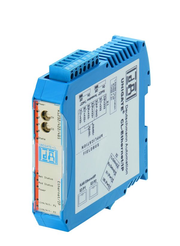
Introduction                                              Deutschmann Automation GmbH & Co. KG

3      Introduction
The UNIGATE® CL-EtherNet/IP 2Port module serves to adapt a serial interface to EtherNet/IP
networks. The device features 2 EtherNet/IP-Ports - one port can e.g. be used as an outgoing
EtherNet/IP-Port. The terminal unit’s protocol is converted in the UNIGATE® via a Script.

The module CL-EtherNet/IP essentially consists of the following hardware components:

• Electrically isolated EtherNet/IP-interface
• Processor "Fido 1100"
• RAM and FLASH
• Optionally electrically isolated on the RS-side
• Serial interface (RS232, RS485 and RS422) to the device connected externally

11                Instruction manual UNIGATE® CL - EtherNet/IP 2Port V. 1.9            12.1.21
Deutschmann Automation GmbH & Co. KG                                               Introduction

3.1    UNIGATE® CL software flow-chart

 12.1.21               Instruction manual UNIGATE® CL - EtherNet/IP 2Port V. 1.9            12
Introduction                                              Deutschmann Automation GmbH & Co. KG

3.2      UNIGATE® application diagram
The following graph shows a typical connection scheme.

13                Instruction manual UNIGATE® CL - EtherNet/IP 2Port V. 1.9            12.1.21
Deutschmann Automation GmbH & Co. KG Operation modes of the Gateway
4 Operation modes of the Gateway
4.1 Configuration mode (config mode)
The configuration mode serves to configure the Gateway. The following adjustments are possible
in this mode.
• Loading a Script (e. g. by means of the software WINGATE with "Write Script" under "File")
• Updating the firmware (e. g by means of the software "FDT")
• Configuration of the Gateway (by means of the software WINGATE)
The Gateway will be starting in this mode in case both switches S4 as well as S5 are set on posi-
tion "F" when switching on the Gateway. Right after switching on the Gateway in the configura-
tion mode it will be sending its starting message, that looks analog with the following message:
"RS-EI-CL(232/422/485) V4.0[36](c)dA Switch=0xFF Script(C:8345/16320,V:7693/8192)
="Universalscript Deutschmann" Author="G/S" Version="V 0.2y" Date=09.01.2012
SN=47110010 IP=10.10.10.10 MAC=00-14-11-15-19-8A“.
In the configuration mode the Gateway always operates with the settings 9600 Bauds, no Parity,
8 Databits and 1 Stopbit, the RS-State LED will always be flashing red, the "Error No/Select ID"
LEDs are of no account for the user. All software revisions contain the configuration mode.
4.2 Test mode
Setting of the test mode
The test mode is set by bringing the switches S4 and S5 in position "E". All other switches will not
be taken into consideration for the setting of the test mode. Now the Gateway has to be restarted
with these settings (by a short disconnection from the power supply).
In the test mode the Gateway always operates with the settings 9600 baud, no parity, 8 databits
and 1 stopbit.
The test mode may be helpful to integrate the Gateway in the relevant environment, for instance
to test the parameters of the RS-interfaces.
Mode of operation of the test mode
After the restart in the test mode the Gateway will be sending the values 0-15 in hexadecimal
representation ("0".."F") in ASCII-coding on the serial side every second. Simultaneously the
same values are issued binary on the fieldbus-interface.
In this mode the State-LED on the RS-side will be flashing red, the "Error No/Select ID" LEDs will
be displaying the value in a binary way, that is issued that moment. Additionally each character
that is received at one of the interfaces will also be output at the same interface as a local echo.
On the fieldbus-side only the first byte will be used for the local echo, that means on receiving as
well as on transmitting only the first byte of the bus data is looked at, the other bus data do not
change compared to the last data.
4.3 Data exchange mode
The Gateway has to be in the data exchange mode, so that a data exchange between the
RS-side of the Gateway and the fieldbus is possible. As long as the Gateway is not in the config-
uration mode or the test mode, the data exchange mode is active. In the data exchange mode
the Gateway will execute the downloaded Script with the parameters, that have been preset
through WINGATE.
12.1.21 Instruction manual UNIGATE® CL - EtherNet/IP 2Port V. 1.9 14RS-interface Deutschmann Automation GmbH & Co. KG 5 RS-interface 5.1 RS-interfaces at the UNIGATE® CL The UNIGATE® CL - Ethernet/IP has the interfaces RS232, RS422 and RS485 available. The hardware always features a DEBUG-interface, see chapter 7. 5.2 Buffer sizes at the UNIGATE® CL UNIGATE® CL features at the serial side a buffer with the size of 1024 bytes for input data and output data each. The FIFO of the application interface (RS-interface) can be changed in any Gateway form Script revision 26 on, that is capable for Script. For it please check in the Protocol Developer under "Device Control" - "Hardware". 5.3 Framing Check The length of the stop bit received by the Gateway is checked through the function "Framing Check". Here the stop bit generated by the Gateway is always long enough, so that connected participants can evaluate the stop bit. Please be aware that the function "Framing Check" becomes effective only in case of 8 data bit and the setting "No parity". An error is detected and indicated by the Error LEDs in case the stop bit does not show the length 1 bit during the activated check. The possible setting for this parameter can be controlled by the Script (see online help from Pro- tocol Developer). The presetting for the "Stop Bit Framing Check" is "enabled". 15 Instruction manual UNIGATE® CL - EtherNet/IP 2Port V. 1.9 12.1.21
Deutschmann Automation GmbH & Co. KG SSI-interface 6 SSI-interface The UNIGATE® also supports the connection of applications or products, that communicate via SSI. 6.1 Initiation of the SSI-interface The configuration of the SSI-interface is executed in the config mode with the WINGATE soft- ware, Protocol SSI. The encoder type and the sampling frequency are defined via the parameter "Resolution" (1 bit..15 bit, 24 bit...25 bit), "SSI Encoder Type" (Binary or Gray code) and "Clock stretch". 6.2 Parameter 6.2.1 Resolution The range extends from 1 bit to 25 bits. This enables single-turn SSI encoders and multi-turn SSI encoders to be configured. 6.2.2 SSI Encoder Type This can be selected between binary and gray code. 6.2.3 Parameter sample frequency (Clock stretch) You can change the sampling frequency. For this purpose a "Stretch value" is passed that inserts a waiting period after each clock edge. If a 0 is passed, there is no waiting time. Thus the following SSI sample frequencies may vary slightly: Waiting time = 0 → SSI-Clock ~ 333kHz (No Stretch) Waiting time = 1 → SSI-Clock ~ 185kHz Waiting time = 2 → SSI-Clock ~ 150kHz Waiting time = 3 → SSI-Clock ~ 125kHz Waiting time = 4 → SSI-Clock ~ 110kHz Waiting time = 5 → SSI-Clock ~ 100kHz Waiting time = 6 → SSI-Clock ~ 88kHz Waiting time = 7 → SSI-Clock ~ 80kHz Waiting time = 8 → SSI-Clock ~ 72kHz Waiting time = 9 → SSI-Clock ~ 67kHz Waiting time = A → SSI-Clock ~ 62kHz Waiting time = B → SSI-Clock ~ 58kHz Waiting time = C → SSI-Clock ~ 54kHz Waiting time = D → SSI-Clock ~ 50kHz Waiting time = E → SSI-Clock ~ 48kHz Waiting time = F → SSI-Clock ~ 45kHz The bit time from which these frequencies were derived, calculate as follows: t = 3μs + (2* (+ 0.6µs (n* 0.6µs))), where n corresponds to the "Stretch value" (1.. F). Without clock extension (n = 0) remains at 3μs → 333kHz! The max. Bit length of 32 bits and the slowest clock this results in a total readout time of 32 * = 22μs ~ 700μs. 12.1.21 Instruction manual UNIGATE® CL - EtherNet/IP 2Port V. 1.9 16
SSI-interface Deutschmann Automation GmbH & Co. KG 6.2.4 Parameter Encoder monitoring (Check Encoder) An encoder monitoring can be activated via the parameter "Check encoder", as long as the used SSI-encoder supports this function. After the last read encoder bit it is verified if the data line is still at Low for at least one bit. If the UNIGATE® does NOT detect this bit on Low, error 12 is issued. For example it can detect a cable break or a not connected encoder. However, it can also be a misconfigured bit length, or a too slow read out clock. 6.3 Hardware-wiring The clock wires of the SSI-interface are placed onto the Tx-wires of the RS422-interface and the data wires onto the Rx-wires at the UNIGATE® CL. X1 (3pin + 4pin screw-plug-connector): Pin no. Name Function at SSI 1 Rx 232 n. c. 2 Tx 232 n. c. 3 AP-GND n. c. 4 Rx 422+ SSI DAT+ 5 Rx 422- SSI DAT- 6 Tx 422+ SSI CLK+ 7 Tx 422- SSI CLK- 17 Instruction manual UNIGATE® CL - EtherNet/IP 2Port V. 1.9 12.1.21
Deutschmann Automation GmbH & Co. KG                                             The Debug-interface

7     The Debug-interface
7.1     Overview of the Debug-interface
The UNIGATE® IC features a Debug-interface, that allows a step-by-step processing of a Script.
Normally this interface is only required for the development of a Script.

7.2     Starting in the Debug-mode
When applying power to the UNIGATE® (power up) the firmware will output the binary character
0 (0x00) after a self-test was carried out on this interface. If the UNIGATE® receives an
acknowledgement via this interface within 500 ms, it is in the Debug-mode. The
acknowledgement is the ASCII-character O (0x4F).
With the start in the Debug-mode the further execution of Script commands will be put to a stop.

7.3     Communication parameter for the Debug-interface
The Debug-interface is always operating with 9600 baud, no parity, 8 data bit, 1 stop bit. It is not
possible to change this parameter in the Protocol Developer. Please consider the fact that these
settings have to be in accordance with those of the PC-COM-interface and that the flow control
(protocol) has to be set on „none“ there.

7.4     Possibilities with the Debug-interface
Usually the Protocol Developer is connected to the Debug-interface. With it a step-by-step pro-
cessing of a Script, monitoring jumps and decisions and looking at memory areas is possible.
Moreover breakpoints can be set. It basically possesses all characteristics a software-develop-
ment tool is typically supposed to have. However, it is also possible to carry out a Scrip-update
via this interface.
From Script version [27] on you can also output data with the Script command
"SerialOutputToDebugInterface". Please also pay attention to the remark in the manual
’Protocol Developer’.

7.5     Commands of the Debug-interface
The commands for the use of the Debug-interface are described in the instruction manual Proto-
col Developer.

 12.1.21                Instruction manual UNIGATE® CL - EtherNet/IP 2Port V. 1.9                 18
Mode of operation of the system                              Deutschmann Automation GmbH & Co. KG

8      Mode of operation of the system
8.1      General explanation
Communication can be split into seven layers, Layer 1 to Layer 7, in accordance with the
ISO/OSI model.
The Deutschmann Automation Gateways convert Layers 1 and 2 of the customized bus system
(RS485 / RS232 / RS422) to the corresponding Fieldbus system. Layers 3 and 4 are being cov-
ered by the UDP/IP-protocol, TCP/IP-protocol. The Layers 5 and 6 are EtherNet/IP. Layer 7 is
converted in accordance with chapter 8.3.

8.2      Interfaces
The Gateway features the RS232-, RS422- and RS485-interfaces.

8.3      Data exchange
All data is transferred by the Gateway in dependence of the downloaded Script.

8.4      Possible data lengths
The table below shows the maximum transferable data:
Input data                   max. 1060 bytes         Variable: maximum value in this case
Output data                  max. 1060 bytes         Variable: maximum value in this case

8.5      Startup phase
The Master sets up a TCP/IP- or a UDP/IP-connection to the Gateway during the startup phase.
Only after a correct termination of the startup phase the data exchange with external devices will
take place.

19                   Instruction manual UNIGATE® CL - EtherNet/IP 2Port V. 1.9              12.1.21
Deutschmann Automation GmbH & Co. KG                                                Generating a Script

9     Generating a Script
9.1     What is a Script?
A Script is a sequence of commands, that are executed in that exact order. Because of the fact
that also mechanisms are given that control the program flow in the Script it is also possible to
assemble more complex processes from these simple commands.

The Script is memory-oriented. It means that all variables always refer to one memory area.
While developing a Script you do not have to take care of the memory management though. The
Protocol Developer takes on this responsibility for you.

9.2     Memory efficiency of the programs
A Script command can carry out e. g. a complex checksum like a CRC-16 calculation via data.
For the coding of this command only 9 byte are required as memory space (for the command
itself). This is only possible when these complex commands are contained in a library.
A further advantage of this library is, that the underlying functions have been in practical use for a
couple of years and therefore can be described as ’void of errors’. As these commands are also
present in the native code for the controller, at this point also the runtime performance of the
Script is favorable.

9.3     What can you do with a Script device?
Our Script devices are in the position to process a lot of commands. In this case a command is
always a small firmly outlined task. All commands can be put into classes or groups. A group of
commands deals with the communication in general. This group’s commands enable the Gate-
way to send and receive data on the serial side as well as on the bus-side.

9.4     Independence of buses
Basically the Scripts do not depend on the bus, they are supposed to operate on. It means that a
Script which was developed on a PROFIBUS Gateway can also be operated on an Interbus with-
out changes, since the functioning of these buses is very similar. In order to also process this
Script on an Ethernet Gateway, perhaps further adjustments have to be made in the Script, so
that the Script can be executed reasonably.
There are no fixed rules how which Scripts have to operate properly. When writing a Script you
should take into account on which target hardware the Script is to be executed, so the necessary
settings for the respective buses can be made.

9.5     Further settings at the Gateway
Most devices require no further adjustments, except for those made in the Script itself. However,
there are also exceptions to it. These settings are made by means of the software WINGATE. If
you know our UNIGATE®-series, you are already familiar with the proceeding with it. An example
is the adjustment of the IP-address and the net-mask of an Ethernet-Gateway. These values
have to be known as fixed values and are not available for the runtime. Another reason for the
configuration of the values in WINGATE is the following: After an update of the Script these val-
ues
remain untouched, i. e. the settings that were made once are still available after a change of
the Script.
Only this way it is also possible that the same Script operates on different Ethernet-Gateways,
that feature different IP-addresses.

 12.1.21                 Instruction manual UNIGATE® CL - EtherNet/IP 2Port V. 1.9                  20
Generating a Script                                           Deutschmann Automation GmbH & Co. KG

9.6      The use of the Protocol Developer
The software tool Protocol Developer can be downloaded from our website
http://www.deutschmann.de
It is a tool for an easy generation of a Script for our Script Gateways. Its operation is exactly
aimed at this use. After starting the program the Script that was loaded the last time is loaded
again, provided that it is not the first start.

Typical for Windows Script commands can be added by means of the mouse or the keyboard. As
far as defined and required for the corresponding command, the dialog to the corresponding
command is displayed, and after entering the values the right text is automatically added to the
Script. The insertion of new commands by the Protocol Developer is carried out in a way that
existing commands will not be overwritten. Generally a new command is inserted in front of the
one where the cursor is positioned. Of course the commands can also be written by means of the
keyboard or already written commands can also be modified.

21                    Instruction manual UNIGATE® CL - EtherNet/IP 2Port V. 1.9            12.1.21
Deutschmann Automation GmbH & Co. KG      Implemented protocols in UNIGATE® CL with Universal Script

10 Implemented protocols in UNIGATE® CL with Universal
   Script
UNIGATE® CL is supplied with the Script “Universal Script Deutschmann“. The configuration of
the protocols is carried out by means of the software WINGATE. See "Instructions UNIGATE® CL
- Configuration with WINGATE". The PDF can also be found on our website under Support/Sup-
port/Downloads/Manuals.

                 Attention: If a Reset Device is carried out it is possible (depending on the
                 firmware version of the UNIGATE) that the "Universal Script" will get lost
                 and must be played in again.
                 If you no longer have the compiled script, a corresponding request must
                 be sent to Deutschmann Support.
                 https://www.deutschmann.de/en/support/enquiry/

10.1 Protocol: Transparent
The data is transferred bidirectional from the UNIGATE®.

10.1.1 Data structure

10.2 Protocol: Universal 232

                 The protocol designation "Universal 232" and the relation to the
                 "RS232-interface" in the description have eveloped over the years. The
                 protocol also works with RS422 and RS485 though!

10.2.1 Data structure

10.2.2 Fieldbus parameters
Trigger byte: See "The trigger byte", Chapter 10.9‚ on page 41
Length byte: See "The length byte", Chapter 10.10‚ on page 41

 12.1.21               Instruction manual UNIGATE® CL - EtherNet/IP 2Port V. 1.9                  22
Implemented protocols in UNIGATE® CL with Universal Script Deutschmann Automation GmbH & Co. KG
10.2.3 RS232 parameter table
10.2.3.1 Start character (232 Start character)
If this character is defined, the gateway evaluates only the data at the RS232 interface following
this start character. Each transmission from the gateway via the RS232 interface is initiated with
the start character in this case.
10.2.3.2 Length 232 (232 Length)
If this byte is activated, the gateway, at the receive end, awaits as many bytes of useful data as
specified in this byte by the RS232 transmitter. At the transmission end, the gateway then sets
this byte to the number of useful data items transmitted by it. If byte "Length232" is not defined,
the gateway, on reception at the RS232 interface, waits for the end criterion if this is defined. If no
end criterion is defined either, as many characters as can be transferred in the fieldbus transmit
buffer are read in via the RS232 interface.
As a special case for this parameter also a length byte with additional Timeout monitoring can be
set in WINGATE. In that case the received characters will be discarded at a Timeout.
Attention:
If "Timeout“ is selected as end character, then this byte has no significance.
10.2.3.3 Timeout
If the end character is set to "FF", the value that was set in the RX_Timeout parameter is acti-
vated and the time entered there is waited for with serial reception, or triggered for new charac-
ters. If the set time is exceeded without an event, the end criterion is reached and the characters
are copied onto the bus.
10.2.3.4 End character (232 End character)
If this character is defined, the gateway receives data from the RS232 interface up to this charac-
ter. The "Timeout" criterion can be defined as a special case. In this case, the gateway continues
to receive characters until a defined pause occurs. In the special case "Timeout" the "Length
232-byte" has no significance. At the transmit end, the gateway inserts the end character, if
defined, as the last character of a transmission.
10.2.4 Communication sequence
The useful data (data area) arriving via the fieldbus is copied in accordance with chapter 10.2.1
transparently into the RS232 data field and transferred via the RS interface, whereby the protocol
is supplemented in accordance with the configuration (start character, end character...). NO
acknowledgement is issued !
If the "Trigger byte“ (see chapter 10.9) is active, data is sent only on a change of this byte. If the
"Length byte" (see chapter 10.10) is active, only as many of the following bytes as specified there
are transferred.
23 Instruction manual UNIGATE® CL - EtherNet/IP 2Port V. 1.9 12.1.21Deutschmann Automation GmbH & Co. KG Implemented protocols in UNIGATE® CL with Universal Script Receive data at the RS interface is evaluated in accordance with the configured protocol, and the data field (data area (see chapter 10.2.1)) is sent to the fieldbus Master. If more characters have been received than the fieldbus block length, the trailing bytes are truncated and an Rx Overrun is indicated. If less have been received, padding with 0 occurs. If the "Length byte" is active, the number of received useful data items is entered there. If the, "Trigger byte" is active, this is incre- mented by one after each complete reception operation at the RS interface. 10.3 Protocol: 3964(R) The 3964 protocol is used to transfer data between two serial devices. One partner must be a high-priority partner and the other must be a low-priority partner in order to resolve initialisation conflicts. 10.3.1 Data structure 3964R 10.3.2 Protocol definitions The telegram format is as follows: STX Data DLE ETX BCC • The received net data is forwarded (transparently) in both directions unchanged. Attention: The DLE-doubling is excluded from it; that means one DLE (10H) on the bus-side is sent on the RS-side twice. A double DLE on the RS-side is only sent once to the bus-master. • Data blocking is not scheduled. • The net data length is restricted to 236 bytes per telegram. • Communication always runs between high-priority and low-priority communication partners. 10.3.3 Data communication 10.3.3.1 Initiation of data communication by the low-priority user If the low-priority user also receives an STX in response to a transmitted STX, it interrupts its transmit request, reverts to Receive mode and acknowledges the received STX with DLE. A DLE in the data string is duplicated and included in the checksum. The BCC is computed from XORing all characters. 10.3.3.2 Conflicts 10.3.3.3 Timeout times The timeout times are preset by the definition of the 3964R protocol and cannot be overwritten !!! tq = acknowledgement timeout time (2 s). The acknowledgement timeout time is started after transmission of control character STX. If no positive acknowledgement arrives within the acknowledgement timeout time, the job is repeated (max. 2 x). If it has not been possible to complete the job positively after two repetitions, the high-priority device nevertheless attempts to establish contact with the low-priority partner by transmitting STX (cycle corresponds to tq). tz = character timeout time ( 200 ms) 12.1.21 Instruction manual UNIGATE® CL - EtherNet/IP 2Port V. 1.9 24
Implemented protocols in UNIGATE® CL with Universal Script Deutschmann Automation GmbH & Co. KG
If the 3964 R driver receives data, it monitors arrival of the individual characters within period tz.
If no character is received within the timeout time, the protocol terminates transfer. No
acknowledgement is sent to the coupling partner.
10.3.3.4 Retries
In the event of negative acknowledgement or timeout, a telegram transmitted by the high-priority
user is repeated twice. After this, the gateway signals communication as disturbed but still
attempts to re-establish the connection.
10.3.3.5 Initiation of data communication by the high-priority user
In the case of a negative acknowledgement or timeout, a telegram transmitted by the external
device is repeated twice before a fault is signalled.
10.3.4 Protocol type 3964
The difference to protocol type 3964R is:
1. tq = acknowledge monitoring time
2. The checksum byte BCC is missing.
10.4 Protocol: MODBUS-RTU
10.4.1 Notes
For reasons of simplicity, "MODBUS-RTU“ is referred to as "MODBUS“ in the text below.
The terms "input“ and "output“ are always viewed from the gateway’s point of view,
i.e. fieldbus input data is the data sent by the fieldbus Master to the gateway.
10.4.2 UNIGATE® as MODBUS-Master
10.4.2.1 Preparation
Before data exchange is commenced, the parameters "Baud rate", "Parity", "Start bits", "Stop
bits" and "Data bits" and, if applicable, the "Trigger byte" and the "Length byte" must be set.
In addition, a "Response time" which corresponds to the maximum time up to which the Modbus
Slave responds after a request must be set. UNIGATE multiplies the value entered in WINGATE
by 10 ms.
The user can choose whether the fieldbus requests are forwarded to the Modbus in an
event-driven way (On Event) or on request (On Trigger).
The mode "Modbus request on demand" necessitates the first byte in the fieldbus containing a
trigger byte (see chapter 10.9). This byte is not transferred to the Modbus and serves only to start
a Modbus transmission. For this purpose, the gateway constantly monitors this trigger byte and
sends data to the Modbus only when this byte has changed. In the reverse direction (to the field-
bus), the gateway transfers the number of received Modbus data records in this byte, i.e. this
byte is incremented by the gateway after each data record.
If the "Length byte“ is activated (see chapter 10.10), the gateway transfers only the number of
bytes specified there. The number of received Modbus data items is saved in the direction of the
fieldbus Master. The length always refers to bytes "Address" to "Dat n" (inclusive in each case),
always without CRC checksum.
25 Instruction manual UNIGATE® CL - EtherNet/IP 2Port V. 1.9 12.1.21Deutschmann Automation GmbH & Co. KG Implemented protocols in UNIGATE® CL with Universal Script 10.4.2.2 Data structure 10.4.2.3 Communication sequence The gateway always acts as the Slave with respect to the fieldbus and always acts as the Master at the Modbus end. Thus, data exchange must always be started by the fieldbus Master. The gateway fetches this data which must be structured in accordance with chapter "Data structure“, from the fieldbus Master, determines the valid length of the Modbus data if the length byte is not activated, adds the CRC checksum and sends this data record as a request on the Modbus. The response of the selected Slave is then sent to the fieldbus Master by the gateway - without CRC checksum. If no response occurs within the stipulated "Response time", the gateway sig- nals a "TIMEOUT ERROR". 10.4.3 UNIGATE® as MODBUS-Slave 10.4.3.1 Preparation Before data exchange is commenced, the parameters "Trigger byte" and "Length byte", "Baud rate", "Parity", "Start bits", "Stop bits" and "Data bits" must be set. At the rotary switch on the RS-side the MODBUS-ID has to be set, under which the gateway is addressed in the Modbus. 10.4.3.2 Data structure 10.4.3.3 Communication sequence The gateway always acts as the Slave with respect to the fieldbus and also acts as Slave at the Modbus end. A data exchange is always initiated by the MODBUS-Master via the RS-interface. If the Modbus-address (1st Byte) which is sent out by the Modbus-Master is identical with the address set on the gateway, the gateway sends the received data (without Modbus-address and CRC-check sum) to the fieldbus-master (look picture above). With it the gateway optionally com- pletes as an introduction a Trigger byte and a Length byte. The fieldbus-master detects when it has to analyse a record via the Trigger byte which is incre- mented by the gateway at every inquiry. The number of the following Modbus-data is to be found in the length byte. Now the fieldbus-master has to analyse the Modbus-inquiry and it has to send back the answer in the same format (optionally with the leading Trigger byte and Length byte) via the fieldbus to the gateway. 12.1.21 Instruction manual UNIGATE® CL - EtherNet/IP 2Port V. 1.9 26
Implemented protocols in UNIGATE® CL with Universal Script Deutschmann Automation GmbH & Co. KG
The gateway then takes this answer and completes the Modbus-address and the CRC and
sends the data to the Modbus-Master via the RS-interface. With it the data exchange is com-
pleted and the gateway waits for a new inquiry from the Modbus-Master.
10.4.4 UNIGATE® as Modbus-ASCII Master
On request!
-> For the description see chapter 10.4.2 "UNIGATE® as MODBUS-Master"
10.5 Protocol „Universal Modbus RTU Slave“
The UNIGATE® is a Modbus slave on the application side. The slave ID is set with the rotary
coding switches S4 + S5 (S4 = High, S5 = Low).
10.5.1 Data structure on the fieldbus side e.g.: PROFIBUS
Applies to In and Out
1. Byte: trigger byte, optional (see chapter 10.9, The trigger byte)
2. Byte: fieldbus length byte, optional (see chapter 10.10, The length byte)
3. Byte: process data
4. Byte: process data
.…
Data structure
10.5.1.1 Example: FC1 + FC2
A Modbus Master (external device) sends a request with function code 1 or 2.
Note:
Modbus Master Request Address (High + Low)
Address request 01 .. 08 will always be on address 01.
Address request 09 .. 16 will always be on address 09.
Address request 17 .. 24 will always be on 17.
…
Configuration:
Fieldbus sends to UNIGATE®
08 01 02 03 04 05 06 07 08 09 0A 0B 0C 0D 0E 0F 10 11 12 13 14 15 16 17 18 19 1A...
27 Instruction manual UNIGATE® CL - EtherNet/IP 2Port V. 1.9 12.1.21Deutschmann Automation GmbH & Co. KG Implemented protocols in UNIGATE® CL with Universal Script Note: The 1. byte (0x08) is the fieldbus length byte. This means only the following 8 Bytes are stored in the UNIGATE®. Connected Modbus Master sends request to the RS232/484 side of the UNIGATE®: Start-Address 0001, Length 56 (38h), FC1 (-Read Coil Status) [01] [01] [00] [00] [00] [38] [3d] [d8] UNIGATE® sends response via RS232/485: [01] [01] [07] [01] [02] [03] [04] [05] [06] [07] [6b] [c5] Display of the data in the Modbus Master (FC1): Example: StartAddress 0008, Length 80, FC2 (Read Input Status) [01] [02] [00] [07] [00] [50] [c9] [f7] UNIGATE® sends response via RS232/485: [01] [02] [0a] [02] [03] [04] [05] [06] [07] [08] [00] [00] [00] [8f] [7a] 10.5.1.2 Example: FC3 (Read Holding Register) + FC4 (Read Input Register) Fieldbus sends to the UNIGATE® 00 30 02 03 04 05 06 07 08 09 0A 0B 0C 0D 0E 0F 10 11 12 13 14 15 16 17 18 19 1A 20 20 20... (The configuration is "Data exchange = On Trigger", with an additonal 1. control byte in the field- bus data.) „Fieldbus length byte = active“, in this example 30h (48d), the UNIGATE® copies the following 48 Byte from the fieldbus into the internal storage. Connected Modbus Master sends request to the RS232/484 side of the UNIGATE® [01] [03] [00] [00] [00] [14] [45] [c5] UNIGATE® sends response via RS232/485: [01] [03] [28] [02] [03] [04] [05] [06] [07] [08] [09] [0a] [0b] [0c] [0d] [0e] [0f] [10] [11] [12] [13] [14]... ... [15] [16] [17] [18] [19] [1a] 12.1.21 Instruction manual UNIGATE® CL - EtherNet/IP 2Port V. 1.9 28
Implemented protocols in UNIGATE® CL with Universal Script Deutschmann Automation GmbH & Co. KG Display of the process data in the Modbus Master: 10.5.1.3 Example: Write Single Coil FC5 The Fieldbus Master sent the following data to the UNIGATE® once: 07 01 02 03 04 05 06 07 08 09 0A 0B 0C 0D 0E 0F 10 11 12 13 14 15 16 17 18 19 1A 20 20 20... 1. Byte = Fieldbus length byte The following 7 byte are stored in the UNIGATE®, the rest is not overwritten. With FC1 and the coil length = 80 (10 Bytes) a Modbus Master reads out the following data: The fieldbus output data is only updated if it’s triggered via a write command from the RS side. For example via FC 5 : Address 0002 stays unchanged on 0, however, the fieldbus output data is updated. After a reset they are NULL (1st row) at first and are then updated (2nd row): 29 Instruction manual UNIGATE® CL - EtherNet/IP 2Port V. 1.9 12.1.21
Deutschmann Automation GmbH & Co. KG Implemented protocols in UNIGATE® CL with Universal Script 00 00 00 00 00 00 00 00 00 00 00 00 00 00 00 00 00 00 00 00 00 00 00 00 00 00 00 00 00 00 ... 1F 01 02 03 04 05 06 07 00 00 00 00 00 00 00 00 00 00 00 00 00 00 00 00 00 00 00 00 00 00... The 1. byte is the fieldbus length byte. It contains the number of usable characters, followed by the payload. The user data (internal buffer) is no bigger than1024 byte. In the following example the Bit (Coil) in Address 0002 is set to High (1): The fieldbus data is updated: 1F 03 02 03 04 05 06 07 00 00 00 00 00 The internal buffer reserves this value, which means it can be read back by the Master via FC1 Read Coil status: 10.5.1.4 Example: Write Single Register FC6 Modbus Master sends the value 1234H in Address 0008: Der Modbus Master sends the request to the UNIGATE®: [01] [06] [00] [07] [12] [34] [35] [7c] The UNIGATE® sends a response: [01] [06] [00] [07] [12] [34] [35] [7c] 12.1.21 Instruction manual UNIGATE® CL - EtherNet/IP 2Port V. 1.9 30
Implemented protocols in UNIGATE® CL with Universal Script Deutschmann Automation GmbH & Co. KG
The 1st row shows the fieldbus data BEFORE the write command:
1F 03 02 03 04 05 06 07 00 00 00 00 00 00 00 00 00 00 00 00 00 00 00 00 00 00 00 00 00 00... .
1F 03 02 03 04 05 06 07 00 00 00 00 00 00 00 12 34 00 00 00 00 00 00 00 00 00 00 00 00 00...
The 2nd row shows the fieldbus data AFTER the write command.
You can see that the value 00 07 is send as Address in the Modbus request. (As mentioned in
the chapter Universal Modbus Master some Master pull System one as offset.)
This leads to the Byte-Offset for the fieldbus output data => 14. You start counting with the first
process data value with Index NULL.
1F 03 02 ….
| +---- 1. process value
+-------- fieldbus length byte
10.5.1.5 Example: Force multiple coils FC 15
Note: The address can only be passed in multiples of 8 incl. Null.
Also 0, 8, 16, … (Here you also have to keep in mind the offset of 1)
Example: Start address = 0001.
Adr 0002 ... 004 was changed from Low to High
The 1st row shows the fieldbus BEFORE the request:
1F 00 FF 03 04 05 06 07 FF 00 00 00 00 00 00 00 00 00 00 00 00 00 00 00 00 00 00 00 00 00...
1F 0E FF 03 04 05 06 07 FF 12 05 12 06 00 00 00 00 00 00 00 00 00 00 00 00 00 00 00 00 00...
2nd row AFTER the request.
Therefor the 1. process data value changed from 00h to 0Eh.
31 Instruction manual UNIGATE® CL - EtherNet/IP 2Port V. 1.9 12.1.21Deutschmann Automation GmbH & Co. KG Implemented protocols in UNIGATE® CL with Universal Script 10.5.1.6 Example: Preset multiple register FC16 Only the content of the register address 0005 and 0006 was changed. The 1st row shows the fieldbus BEFORE the request: 1F 0E FF 03 04 05 06 07 FF 00 00 00 00 00 00 00 00 00 00 00 00 00 00 00 00 00 00 00 00 00... 1F 0E FF 03 04 05 06 07 FF 12 05 12 06 00 00 00 00 00 00 00 00 00 00 00 00 00 00 00 00 00... The 2nd row shows the fieldbus data content AFTER the update. 12.1.21 Instruction manual UNIGATE® CL - EtherNet/IP 2Port V. 1.9 32
Implemented protocols in UNIGATE® CL with Universal Script Deutschmann Automation GmbH & Co. KG
10.6 Protocol „Universal Modbus RTU Master“
The UNIGATE® is Modbus-Master on the Application side.
10.6.1 Data structure Fieldbus side (e.g. PROFIBUS):
Applies to In and Out
1. Byte: Trigger-Byte, optional (see chapter 10.9, The trigger byte)
2. Byte: Fieldbus length byte, optional (see chapter 10.10, The length byte)
3. Process data
Data structure
10.6.2 Data structure Application side:
According to Modbus RTU Master definition.
Supported functions:
Read coil status FC1 (No. of Points = Bit)
Read input status FC2 (No. of Points = Bit)
Read multiple register FC3 (No. of Points = Word)
Read input registers FC4 (No. of Points = Word)
Force single coil FC5 (No. of Points – not used = fix 1 Bit)
Preset single register FC6 (No. of Points – not used = fix 1 Word)
Force multiple coils FC15 (No. of Points = Bit)
Preset multiple register FC16 (No. of Points = Word)
Note:
status and coil = 1 Bit, register = 16 Bit.
FC 1 + 2 as well as FC 3 + 4 are principally the same, the only difference is the definition of the
start address.
At FC1 it starts at Null, at FC2 at 10 000.
At FC3 it starts at 40 000, at FC4 at 30 000
33 Instruction manual UNIGATE® CL - EtherNet/IP 2Port V. 1.9 12.1.21Deutschmann Automation GmbH & Co. KG Implemented protocols in UNIGATE® CL with Universal Script
10.6.3 Configuration: via Wingate since wcf Datei Version 396
Parameter Name value range Explanation
Modbus Timeout (10ms) 1 ... 255 (10ms ... 2550ms) Max. Waiting time for the "Response" before
an error 9 is generated by timeout. If "RX Poll
Retry" > 0 an error is only generated after
retries.
RX Poll Retry Retry of the last, invalid replied
"Request"
RX Poll Delay (10ms) Pause before the next “Request”
Configurations parameter for a Modbus Request:
Req. 1 Slave ID: Slave ID of the Modbus slave participant
Req. 1 Modbus Function: see “supported functions”
Req. 1 StartAdr (hex): Start address (High / Low) of the Modbus register from which should be
read/written
Req. 1 No. of Points (dec): Number of the to read/to write register/coils
Req. 1 Fieldbus Map Adr(Byte): Position of the to be copied process value from/to the fieldbus
range, depending on the write/read-command. If the value is NULL the process data is automati-
cally lined up behind the other.
Up to 24 requests can be configured.
Additional configuration possibilities in the setting „Req. … Modbus Function“:
jump to Req. 1: jump to 1. request entry
disable this Req.: skip this request and perform the next request entry.
„(10ms)“ : adjustable in 10ms steps
„(hex)“: Enter in hexadecimal style.
„(dec)“: Enter in decimal style.
„(Byte)“: Counting in bytes, starting at the position Null. Attention: For read commands, e.g. FC3, after the trigger- and
lenghtbyte the first process value is the postion nulll, which is copied to the fieldbus to the PLC.
For write commands, e.g. FC16, the position Null is the trigger byte.
12.1.21 Instruction manual UNIGATE® CL - EtherNet/IP 2Port V. 1.9 34Implemented protocols in UNIGATE® CL with Universal Script Deutschmann Automation GmbH & Co. KG 10.6.3.1 Example: Read coil status FC1 Configuration Data content Modbus Slave UNIGATE® reads Address 5 + 6 and copies it into the 6. byte of the output buffer. Fieldbus output data (UNIGATE® -> SPS) 66 07 00 00 00 00 00 00 01 00 00 00 00 00 00 00 00 00 00 00 0 1. Byte = Trigger byte (value = 0x66 ) 2. Byte = Fieldbus length byte (value = 0x07) 3. Byte = Fieldbus Map Adr 0 (value = 0x00) 4. Byte = Fieldbus Map Adr 1 (value = 0x00) 5. Byte = Fieldbus Map Adr 2 (value = 0x00 ) 6. Byte = Fieldbus Map Adr 3 (value = 0x00) 7. Byte = Fieldbus Map Adr 4 (value = 0x00) 8. Byte = Fieldbus Map Adr 5 (value = 0x00) 9. Byte = Fieldbus Map Adr 6 (value = 0x01) see configuration 10. Byte = Fieldbus Map Adr 7 (value = 0x00) 11. Byte … In the following example the value in address 6 in the Modbus Master is changed from 0 to 1. 35 Instruction manual UNIGATE® CL - EtherNet/IP 2Port V. 1.9 12.1.21
Deutschmann Automation GmbH & Co. KG Implemented protocols in UNIGATE® CL with Universal Script AD 07 00 00 00 00 00 00 01 00 00 00 00 00 00 00 AE 07 00 00 00 00 00 00 03 00 00 00 00 00 00 00 The modification can be seen here: 9. Byte = Fieldbus Map Adr 6 (Wert = 0x01) => 0x03 A modification of address 7 in the Modbus slave has no consequences to the fieldbus output side because "No. Of Points = 2" is set in the configuration. The value stays unchanged on 0x03: 1F 07 00 00 00 00 00 00 03 00 00 00 0 10.6.3.2 Example: Read input status FC2 The following example shows the content of address 10007 ... 10009 is mapped/copied into the 8. fieldbus output byte. 76 09 00 00 00 00 00 00 00 00 01 00 00 00 00 12.1.21 Instruction manual UNIGATE® CL - EtherNet/IP 2Port V. 1.9 36
Implemented protocols in UNIGATE® CL with Universal Script Deutschmann Automation GmbH & Co. KG
Here the content of the address 10009 is changed from 0 -> 1
In the following example only the "No. Of Points" is switched to 10.
Which means that now 10 Bits => 2 Byte are read out. This is also the reason why the fieldbus
length byte (2. fieldbus byte) at 0x0A increases by 1 Byte.
10.6.3.3 Example: Read multiple register FC3
RX Poll Delay = 0 is automatically set to 1 by the firmware.
Modbus-Request:
Byte 1 Byte 2 Byte 3 Byte 4 Byte 5 Byte 6 Byte 7 Byte 8
Slave ID Modbus StartAdr StartAdr No. of No. of CRC High CRC Low
Function High Low Points Points
High Low
1 3 0x00 0x01 0 2 x y
The CRC value is automatically calculated by the UNIGATE®
The UNIGATE® sends out the request (RX Poll Retry = 0) one time via the RS interface, and waits a maxi-
mum of 250 ms (Modbus Timeout = 25) on the response.
Fieldbus Map Adr = 0 -> not activ
37 Instruction manual UNIGATE® CL - EtherNet/IP 2Port V. 1.9 12.1.21Deutschmann Automation GmbH & Co. KG Implemented protocols in UNIGATE® CL with Universal Script
Thereby the addressed slave holds the following data in its registers.:
register
address value(hex)
40000 0x0000
40001 0x0202
40002 0x0303
40003 0x0000
40004 0x0000
register = 1 Word = 2 Byte
In the documentation of some applications, an Offset + 1 at the address is assu-
med. The notation for address "40000" stands for "holding register". But in acuta-
lity address 0x0000 is meant by it. This is not uniform in the Modbus-Slave
documentations. (E.g. the PC simulation tool "ModSim32" has this offset).
If a valid response is received, the four byte (No. Of Points = 2) process value (Modbus-Data) will
be copied to the fieldbus from "Fieldbus Map Adr(Byte)" = 0 on.
Fieldbus data from UNIGATE® -> SPS:
51 13 02 02 03 03 30 04 01 00 01 00 00 00 02 57 00 01 03 00 00 00 00 00 00 00 ...
Byte 0 = Trigger-Byte „0x51“
Byte 1 = Fieldbus length byte „0x13“
Byte 2 = Process value (High) from StartAdr „0x02“
Byte 3 = Process value (Low) from StartAdr „0x02“
Byte 4 = Process value (High) from StartAdr + 1 „0x03“
Byte 5 = Prozess value (Low) from StartAdr + 1 „0x03“
10.6.3.4 Example: Read input registers FC4
(see chapter 10.6.3.3, Example: Read multiple register FC3)
10.6.3.5 Example: Force single coil FC5
At FC5 a bit is set in the Modbus slave, if the mapped fieldbus byte is bigger (>) than NULL.
Configuration Modbus Slave(impact)SPS sends
Fieldbus data (reason)
Note: No. of Points is not required
Another example for when a second request is configured:
12.1.21 Instruction manual UNIGATE® CL - EtherNet/IP 2Port V. 1.9 38You can also read