SOLAR SIX PACK INSTALLATION MANUAL
←
→
Page content transcription
If your browser does not render page correctly, please read the page content below
SOLAR SIX PACK™
INSTALLATION MANUAL

          BUTLER SUN SOLUTIONS, INC.
 525 Stevens Avenue West, Solana Beach, CA 92075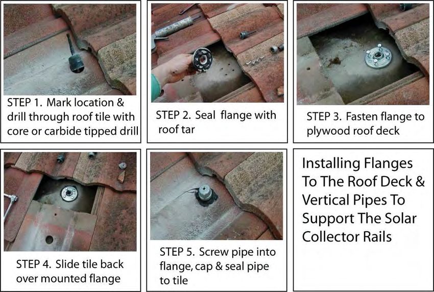
Revision 7                             Solar Six PackTM              Butler Sun Solutions Inc.
August 2012                                                        www.butlersunsolutions.com

                                   REVISION HISTORY
        The latest version of this manual is available for download from our website at:
                                 www.butlersunsolutions.com

       Date         Revision                Features Added In This Edition
January 1, 2003      Initial
                    Release
June 30, 2003          1
October 15, 2003       2
February 11, 2004      3     Anti-scald protection system
July 1, 2005           4     PV power option/revised flush & fill procedures
August 31, 2007        5     Modular solar collectors:
                                Parallel/Series fluid connections
                                Collector mounting rails
                             Control system functions, identification & schematics:
                             Overflow reservoir level minder option: Temperature gauge
                             installation:
                             Evacuated tube mounting requirements:
                             Pump blow up repair diagrams:
                             Anti-scald valve blow up repair diagram:
May 1, 2009            6     Integrated Pump Station; Anti-Scald Heat Trap
August 2012             7       Solar Six Pack™ Simplified Installation

All Rights Reserved                           ii
            Installation Manual: Solar Butler 1.2 Solar-Assisted Hot Water System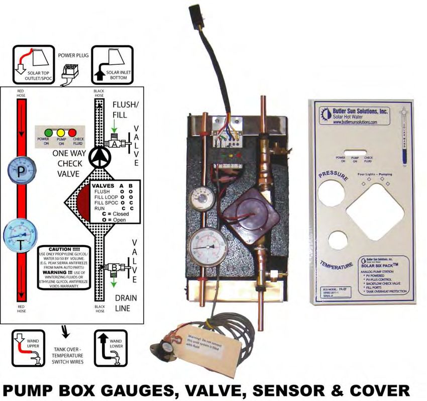
Revision 7                                                   Solar Six PackTM                            Butler Sun Solutions Inc.
August 2012                                                                                            www.butlersunsolutions.com

                                                     TABLE OF CONTENTS
Introduction ..................................................................................................................................... 1
     Solar Rating and Certification Corporation (SRCC) Information ............................... 1
     Tools and Skills Needed .............................................................................................. 2
                 Skills needed by Installer or Do-It-Yourself Handyman ............................ 2
                 Safety Equipment ........................................................................................ 2
                 Supplies You May Need To Provide .......................................................... 3
                 Generic Tools .............................................................................................. 3
                 Special Tools ............................................................................................... 2
     Do’s and Don’ts (What Your Mother Never Told You About Solar Hot Water
            Installation!!) ................................................................................................... 3
     Hazards of All Types ................................................................................................... 4
                 Drinking Water Contamination Hazard ...................................................... 4
                 Hot Water Scalding Hazard ........................................................................ 4
                 Ladder Hazard ............................................................................................. 5
                 Falling Hazard ............................................................................................. 5
                 Electrical Shock and Fire Hazards .............................................................. 5
                 Electrocution Hazards ................................................................................. 5
STEP 1.           Planning The Installation ............................................................................................. 6
   1.1            Installation Overview....................................................................................... 6
   1.2            Planning the Installation .................................................................................. 8
                     1.2.1 Determine True South ..................................................................... 8
                     1.2.2 Choose Collector Tilt Angle ........................................................... 9
      1.3         Collector Location and Orientation ................................................................. 9
      1.4         Collector Selection......................................................................................... 10
      1.5         Routing the Umbilical.................................................................................... 11
STEP 2.           Installing the Solar Collectors        (Can 1) .............................................................. 12
   2.1            Collector Orientation Flow Path Do’s &Don’ts ............................................ 12
   2.2            Serpentine Flow Solar Collectors .................................................................. 13
   2.3            Parallel Flow Solar Collectors ....................................................................... 14
   2.4            Evacuated Tube Collectors ............................................................................ 14
   2.5            Mounting Thermal Collectors........................................................................ 15
STEP 3.           Self-Pressurizing Over-temperature Capsule (SPOC™) (Can 2) .............................. 19
   3.1            Self-Pressurizing Over-temperature Capsule (SPOC™) Description ........... 19
   3.2            Installing the SPOC™ ................................................................................... 22
                     3.2.1 Physical Installation of the SPOC™ ............................................. 22
                     3.2.2 Pressure Testing the System ......................................................... 23
                     3.2.3 Connecting the SPOC™ to the Solar Collector ............................ 24
                     3.2.4 Electrical Connections .................................................................. 24
                     3.2.5 Charging the Solar Hot Water System .......................................... 25
STEP 4.           Umbilical Installation (Can 4) ................................................................................... 26
   4.1            Umbilical Description .................................................................................... 26
   4.2            Installing Umbilical ....................................................................................... 29

All Rights Reserved                           iii
            Installation Manual: Solar Butler 1.2 Solar-Assisted Hot Water System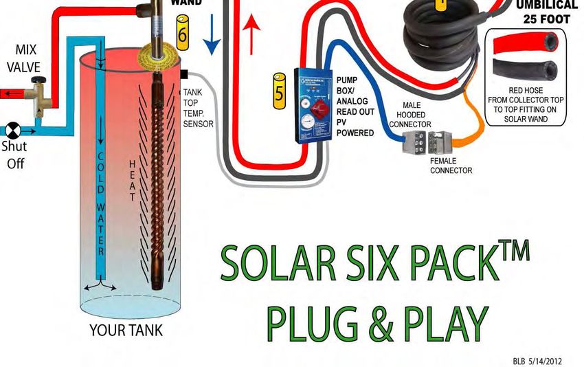
Revision 7                                           Solar Six PackTM                        Butler Sun Solutions Inc.
August 2012                                                                                www.butlersunsolutions.com

                   4.2.1     Physical Installation of Umbilical ................................................. 29
STEP 5.        PV Panel Installation (Can 3) .................................................................................... 31
   5.1         Electrical Connections ................................................................................... 31
                  5.1.1 Connectors on the Roof ................................................................ 31
                  5.1.2 Connector on Controller/Pump Box ............................................. 31
     5.2       Mounting of Photovoltaic Panel .................................................................... 32
STEP 6.        UV Protection of Umbilical on Roof ......................................................................... 33
STEP 7.        “Solar Wand™” Installation (Can 6) ......................................................................... 34
   7.1         Description of Solar Wand™ Heat Exchanger .............................................. 34
   7.2         Installation of the Solar Wand™ Heat Exchanger......................................... 35
                  7.2.1 Disconnect & Depressurize Tank ................................................. 35
                  7.2.2 Inspect Sacrificial Anode .............................................................. 36
                  7.2.3 Prepare Tank for Wand Installation .............................................. 36
                  7.2.4 Checking the Depth Under the Port .............................................. 37
                  7.2.5 Wand Installation .......................................................................... 37
                  7.2.6 Mixing Valve Installation ............................................................. 38
STEP 8.        Pump Box Installation (Can 5) .................................................................................. 40
   8.1         Description of Pump Box .............................................................................. 40
   8.2         Pump Box Installation ................................................................................... 41
   8.3         Pump Box Connections ................................................................................. 41
   8.4         Pump Servicing .............................................................................................. 42
   8.5         Electronic Controls (Delta-T) ........................................................................ 43
STEP 9.        Pump Box-To-Umbilical Connection (Cans 4 and 5) ............................................... 45
   9.1         Route Umbilical ............................................................................................. 45
   9.2         Connect Hoses ............................................................................................... 45
   9.3         Don’t Plug In Power ...................................................................................... 45
STEP 10. Pump Box-To-Tank Connections (Cans 5 and 6)...................................................... 46
   10.1 Connect Hoses ............................................................................................... 46
   10.2 Mount Tank Top Temperature Sensor/Thermostatic Switch ........................ 46
STEP 11.       Flushing & Filling the System ................................................................................... 48
   11.1        Flushing the System with Water .................................................................... 48
   11.2        Antifreeze Preparation ................................................................................... 50
   11.3        Antifreeze Filling Using Gravity ................................................................... 51
   11.4        Antifreeze Filling With a High Pressure Pump ............................................. 52
   11.5        Removing Trapped Air From a Filled System .............................................. 54
   11.6        Antifreeze Maintenance ................................................................................. 54
STEP 12.       Clean Up & System Check Out ................................................................................. 55
   12.1        Install System Labels ..................................................................................... 55
   12.2        Site Clean Up Activities ................................................................................ 56
   12.3        Final System Check List ................................................................................ 56
   12.4        Follow-Up ...................................................................................................... 56
Solar Hot Water System Specifications ........................................................................................ 58

All Rights Reserved                           iv
            Installation Manual: Solar Butler 1.2 Solar-Assisted Hot Water System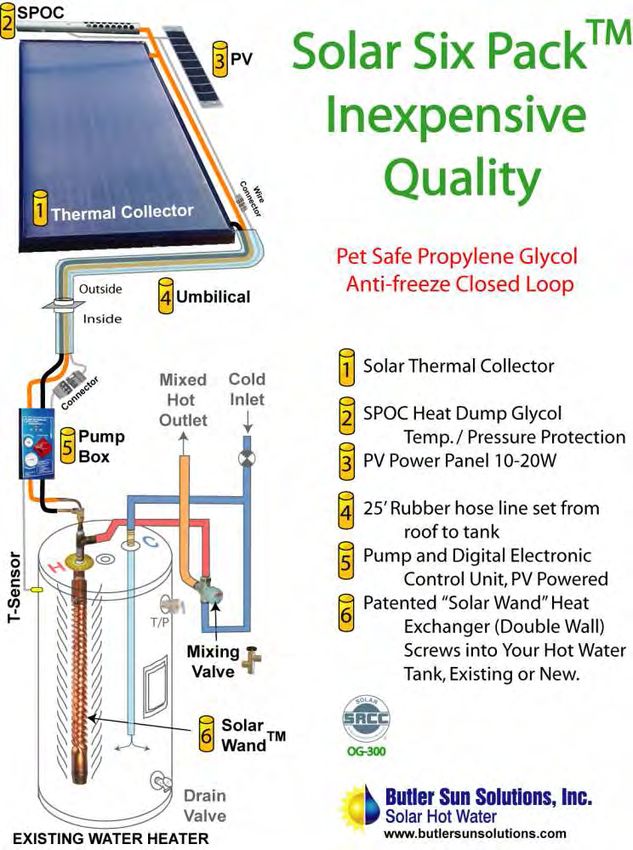
Revision 7                                                Solar Six PackTM                           Butler Sun Solutions Inc.
August 2012                                                                                        www.butlersunsolutions.com

      Overall System........................................................................................................... 58
                System Description ................................................................................... 58
                Component Specifications (by Can Number): .......................................... 58
      Estimated System Performance ................................................................................. 60
      Capacities / Data ........................................................................................................ 60
                Solar Wand™ Specifications .................................................................... 60
                SPOC™ Specifications ............................................................................. 61
System Warranty........................................................................................................................... 63
    SCOPE OF COVERAGE .......................................................................................... 63
    WHAT BUTLER SUN SOLUTIONS WILL DO ..................................................... 63
    WARRANTY PERFORMANCE (Where and How to File Claims) ........................ 63
    LIMITATION OF LENGTH ..................................................................................... 64
    WHAT IS NOT COVERED ...................................................................................... 64
    OTHER RIGHTS AND REMEDIES ........................................................................ 64

                                                      LIST OF FIGURES

Figure 1   Special Tools to Speed Wand and Rubber Hose Installation ....................................... 3
Figure 1.1 Good Installation Planning Results in A Clean, Professional Installation ................... 6
Figure 1.2 BSSI Solar Six Pack™ Solar Hot Water System ......................................................... 7
Figure 1.3 Solar Wand Heat Exchanger, US Patent #6,837,303 B2 .............................................. 8
Figure 1.4 Solar Orientation Factor for San Diego, CA .............................................................. 10
Figure 1.5 Effect of HX Surface Area on Collector Performance ............................................... 11
Figure 2.1 STEP 2 -Collector Mounting ...................................................................................... 12
Figure 2.2 Collector Orientations for Steam Escape ................................................................... 13
Figure 2.3 ACR (Solar Roofs.com) Solar Collector Arrangements and Example of a
              Vertical Column Installation ................................................................................. 14
Figure 2.4 Parallel Flow Collector Connections .......................................................................... 14
Figure 2.5 Properly Mounted Evacuated Tube System ............................................................... 15
Figure 2.6 Roof Mounting Using Flange and Pipe Method......................................................... 17
Figure 2.7 Roof Mounting Figures from HUD Report ................................................................ 17
Figure 2.8 Flange/Pipe Anchor Methods ..................................................................................... 18
Figure 2.9 Shingle Roof Attachment ........................................................................................... 18
Figure 2.10 Rail Mounted Collectors on a Tilted Rack ............................................................... 18
Figure 3.1 STEP 3 SPOC™ Installation ..................................................................................... 19
Figure 3.2 Glycol Temperature/Pressure of SPOC™ & Steam Back Closed Systems. ............. 20
Figure 3.3 SPOC™ Components ................................................................................................. 21
Figure 3.4 How The SPOC™ Works .......................................................................................... 21
Figure 3.5 SPOC™ Replaces Five Parts in Other Solar Hot Water Systems .............................. 22
Figure 3.6 Positions of Components on Roof .............................................................................. 23
Figure 3.7 SPOC™ Mounting Brackets and Clamps .................................................................. 23
Figure 3.8 Pressurizing Pump for System Leak Checking .......................................................... 24
Figure 3.9 Mounting S.P.O.C. unit on Solar Collector ................................................................ 24
Figure 4.1 STEP 4 Overview of Umbilical Under & Over Roof................................................ 26

All Rights Reserved                           v
            Installation Manual: Solar Butler 1.2 Solar-Assisted Hot Water System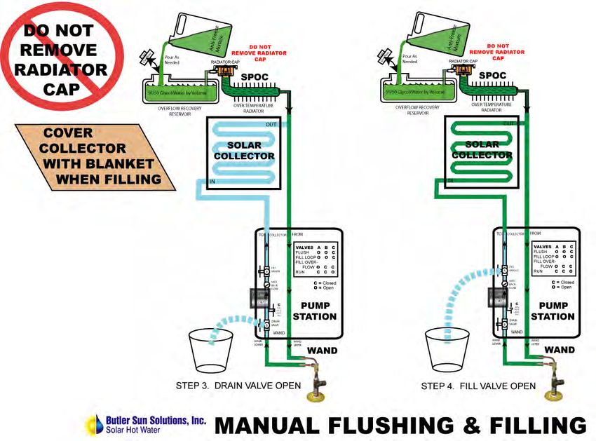
Revision 7 Solar Six PackTM Butler Sun Solutions Inc.
August 2012 www.butlersunsolutions.com
Figure 4.2 Overview of Hose and Electrical Connections ........................................................... 27
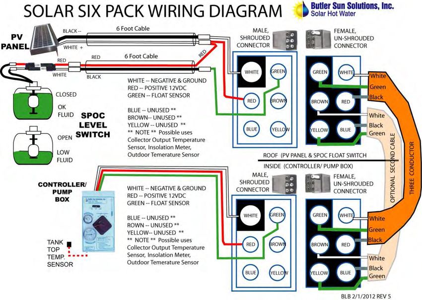
Figure 4.3 System Wiring Diagram ............................................................................................. 28
Figure 4.4 Radiator Hose Clamp Connections (Leak Resistant) ................................................. 29
Figure 4.5 Roof Jack Penetration UV Aluminum or ABS-Split Pipe.......................................... 30
Figure 5.1 STEP 5 PV Panel Mounting & Connector Plugs ...................................................... 31
Figure 5.2 PV Panel for Mounting on Thermal Collector ........................................................... 32
Figure 6.1 STEP 6 UV Umbilical Protection Using Aluminum Cladding ................................. 33
Figure 7.1 STEP 7 Installing the Solar Wand™ Heat Exchanger .............................................. 34
Figure 7.2 Wand-Years of Experience......................................................................................... 35
Figure 7.3 Sacrificial Anode Inspection ...................................................................................... 36
Figure 7.4 Clearing Blocked Tank Port with 15/16” Drill Bit ..................................................... 36
Figure 7.5 Plumbing for Sacrificial Anode on the Hot Water Outlet Nipple .............................. 37
Figure 7.6 Wand Top Leak Check ............................................................................................... 38
Figure 7.7 Proper Mixing Valve Placement ................................................................................ 39
Figure 8.1 STEP 8 Pump Box Placement & Mounting .............................................................. 40
Figure 8.2 Pump Box and Components ....................................................................................... 41
Figure 8.3 Instrument Readings and Meaning ............................................................................. 42
Figure 8.4 Pinch off Clamps ........................................................................................................ 42
Figure 8.5 Ivan Labs EL-SID™ Pump Repair ............................................................................. 43
Figure 8.6 AC vs. PV Powered Pump System ............................................................................. 44
Figure 9.1 STEP 9 Umbilical to Pump Box Connection ............................................................ 45
Figure 10.1 STEP 10 Pump Box to Tank Connections .............................................................. 46
Figure 10.2 Thermostatic Snap Switch Mounting Options ......................................................... 47
Figure 10.3 Tank Top Temperature Sensor ................................................................................. 47
Figure 11.1 STEP 11 Flush & Fill Procedure ............................................................................. 48
Figure 11.2 Flushing Kit for Solar Six Pack ................................................................................. 48
Figure 11.3 Water Fill/Flush Process........................................................................................... 49
Figure 11.4 Peak Sierra™ Antifreeze ........................................................................................... 50
Figure 11.5 Siphoning Fresh Antifreeze Into the System ............................................................ 52
Figure 11.6 Antifreeze Filling Using a Pump System ................................................................. 53
Figure 12.1 STEP 12 Clean Up & Final System Check Out ...................................................... 55
Figure 12.2 Pump Box Instrument Interpretation ........................................................................ 57
LIST OF TABLES
Table 1 SRCC OG-300 System Descriptions ........................................................................... 1
Table 1.1 Approximate Latitudes of Selected U.S. Cities ........................................................... 9
Table 2.1 Roof Mounting Options for Solar Collectors ............................................................ 16
Table 12.1 System Information Labels ........................................................................................ 55
All Rights Reserved vi
Installation Manual: Solar Butler 1.2 Solar-Assisted Hot Water System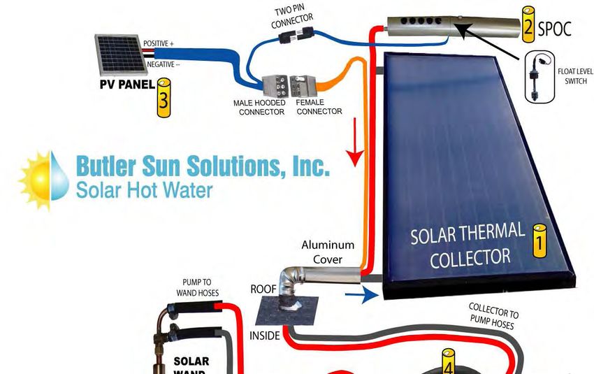
Revision 7                               Solar Six PackTM               Butler Sun Solutions Inc.
August 2012                                                           www.butlersunsolutions.com

                                          ACRONYMS

ABS        Acrylonitrile Butadiene Styrene – a tough, light, and water-resistant plastic, black in
           color, used for drain line pipes. (NOTE: ABS/PVC co-extruded pipe is sold in most
           parts of USA except on the East coast, where they use PVC drain pipe)
BSSI       Butler Sun Solutions, Inc.
PVC        Poly Vinyl Chloride – a plastic used to make drain and sprinkler pipes, white in color
ASTM       American Society for Testing Materials
AWG        American Wire Gauge, a size scale for electrical wires
AWWA American Water Works Association
DIP        Down Inlet Pipe on water heater
GFCI       Ground Fault Circuit Interrupter – a device that detects and opens a circuit if
           electrical current is detected in the ground leg, indicating a ground fault or short-
           circuit
gpm        Gallons per Minute
GPS        Global Positioning System receiver, which can act as both compass and latitude
           measuring device.
Insolation Power coming from the sun per unit of surface area, approximately 1,000 Watts/m2 at
           solar noon. May also be annual daily average which for San Diego is 6.5
           kWh/m2/day.
LCA        Linear Current Amplifier – electronic controller that improves performance of PV-
           powered pumps
NPT        United States National Pipe Thread Standard
pH         Log Scale of H+ ion activity; 1 to 6 is Acidic, 7 is neutral, 8 to 14 is Basic
psi        Pounds per Square Inch – a measure of pressure
psig       Pounds per Square Inch Gauge -- pressure measured above atmospheric pressure
PV         Photovoltaic panel – a flat panel containing solar cells that convert sunlight directly to
           electric power
SPOC™ Self Pressurizing Over-Temperature Capsule – a patented component of the BSSI
           solar hot water system that provides overtemperature protection, as well as pressure
           regulation, air bubble removal, and fluid inventory management for the solar loop.
SOF        Solar Orientation Factor – a measure of relative solar system performance as a
           function of Tilt angle and East-West orientation
SRCC       Solar Rating and Certification Corporation
Stagnation The condition where solar energy is being absorbed by the solar collectors and there
           is no fluid flow to remove the heat.

All Rights Reserved                          vii
            Installation Manual: Solar Butler 1.2 Solar-Assisted Hot Water System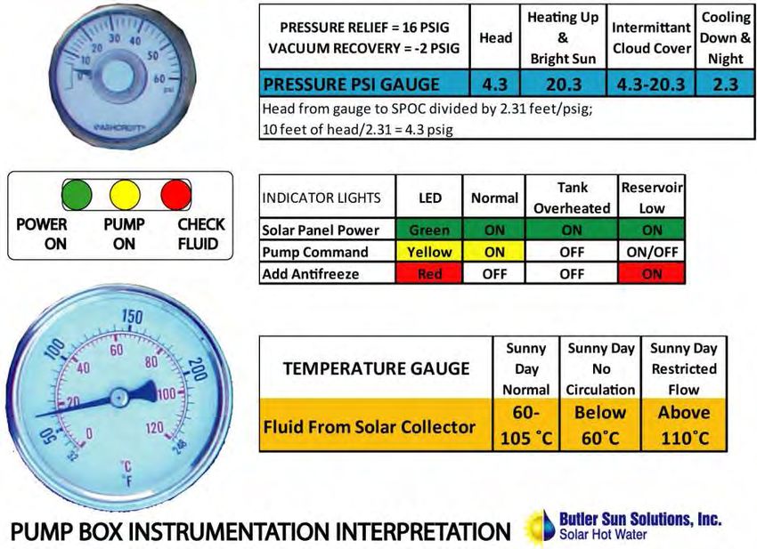
Revision 7                             Solar Six PackTM              Butler Sun Solutions Inc.
August 2012                                                        www.butlersunsolutions.com

Introduction
Solar Rating and Certification Corporation (SRCC) Information
The solar energy system described by this manual, when properly installed
and maintained, meets the minimum standards established by the SRCC. This
certification does not imply endorsement or warranty of this product by
SRCC.
Butler Sun Solutions, Inc. (BSSI) solar hot water systems are SRCC OG-300 certified systems.
SRCC certification indicates the systems meet set standards for quality and operational
effectiveness. SRCC certification is often required for rebate programs, including the Federal
30% tax credit. The following table (Table 1) lists systems that have been certified by the SRCC
as of the time that this manual was prepared. In the System Model Number “PV1” indicates a
Photovoltaic-powered pump is used to circulate the Propylene Glycol antifreeze fluid in the solar
collector loop. “S1” indicates a 115 VAC Delta-T controller is used to power the pump.
Systems have been certified with a variety of popular flat plate and evacuated tube solar
collectors, and as both single tank and dual tank systems in a range of sizes. For a list of the
currently certified BSSI systems and for actual system performance ratings in your region, go to
www.solar-rating.org the SRCC web site.
                       Table 1     SRCC OG-300 System Descriptions

System Model       SRCC                 Collector      Solar     Aux      Solar     Aux
Number             Certification        Area (ft2)     Tank      Tank     Tank      Tank
                   Number                              Vol.      Vol.     Heat      Heat
                                                       (gal)     (gal)
BSS-PV1-40Ea       300-2005-005A           24.6         40                Elec.
BSS-PV1-40Eb       300-2005-005B           20.1         40                Elec.
BSS-PV1-50Ea       300-2005-005C           32.9         50                Elec.
BSS-PV1-80Ea       300-2005-005E           40.9         80                Elec.
BSS-PV1-40Ec       300-2005-005I           40.1         40                Elec.
BSS-PV1-50Ec       300-2005-005H           40.1         50                Elec.
BSS-PV1-80Ec       300-2005-005G           40.1         80                Elec.
BSS-PV1-40Ga       300-2005-006A           24.6         40                Gas
BSS-PV1-40Gb       300-2005-006B           20.1         40                Gas
BSS-PV1-50Ga       300-2005-006C           32.9         50                Gas
BSS-PV1-80Ga       300-2005-006E           40.9         80                Gas
BSS-PV1-40Gc       300-2005-006I           40.1         40                Gas
BSS-PV1-50Gc       300-2005-006H           40.1         50                Gas
BSS-PV1-80Gc       300-2005-006G           40.1         80                Gas
BSS-S1-80E2a       300-2005-007A           40.1         80        50      Sun       Elec.
BSS-S1-80E2b       300-2005-007B           40.9         80        50      Sun       Elec.
BSS-PV1-80E2a      300-2005-008A           40.1         80        50      Sun       Elec.
BSS-PV1-80E2b      300-2005-008B           40.9         80        50      Sun       Elec.

All Rights Reserved                                                               Page 1 of 65
            Installation Manual: Solar Butler 1.2 Solar-Assisted Hot Water System
Revision 7                              Solar Six PackTM                Butler Sun Solutions Inc.
August 2012                                                           www.butlersunsolutions.com

BSS-S1-80G2a        300-2005-009A           40.1          80         50       Sun      Gas
BSS-S1-80G2b        300-2005-009B           40.9          80         50       Sun      Gas
BSS-PV1-80G2a       300-2005-010A           40.1          80         50       Sun      Gas
BSS-PV1-80G2b       300-2005-010B           40.9          80         50       Sun      Gas

Tools and Skills Needed
Following are suggested lists of skills, tools and equipment you may need to successfully
complete the installation of your solar hot water system. Some installations will be easy and all
of the suggested tools may not be required. We have tried to be as comprehensive as possible
with the tool list; however, we do not guarantee that you will not need other tools or supplies,
based on your specific installation situation. Roof installations can be dangerous since there are
hazards such as ladders and slippery, sloped surfaces. If after reading this manual there is any
doubt in your mind about self-installation, hire a professional. Be sure that your licensed
professional has the appropriate liability and Workers’ Compensation Insurance for your state.
We will list qualified professionals on our website as they become known to us. If we don’t list
someone in your area, go to the Solar Energy Industries Association website (www.seia.org) and
look for a SEIA member company in your area. SEIA members subscribe to a strict code of
ethics based on customer satisfaction. The American Solar Energy Society has a new website,
www.findsolar.com, which lists qualified solar hot water installers by postal zip code. Murphy’s
Law may come into play, but Do-It-Yourselfers are very resourceful and will be able to complete
a professional installation and be happy with their new solar hot water system. A growing
gallery of solar systems installed all over the USA is included on our website,
www.butlersunsolutions.com.
Skills needed by Installer or Do-It-Yourself Handyman
   •   Basic carpentry, to route umbilical and cover cladding
   •   Basic roofing skills to secure the collector to the roof without creating water leaks.
   •   Basic plumbing using wrenches and pipe connections
   •   Basic soft solder pipe sweating, if solar collector array is connected by sweat solder
       connections.
   •   Basic electrical to check outlet prior to plugging controller into outlet or connecting
       12VDC for the PV powered system.
Safety Equipment
   •   Rubber soled, lace-up shoes with good traction (no flip-flops or sandals on roofs)
   •   Leather gloves to protect your hands
   •   Safety glasses or a face shield to protect your eyes and face
   •   Electrical outlet polarity and fault detector
   •   Stud, wire and pipe finder
   •   Collector cover such as a tarpaulin, heavy blanket or craft paper
   •   Fire Extinguisher
   •   100-foot, grounded, GFCI extension cord, or cordless tools for drilling, cutting and
       soldering
   •   Extension ladder

All Rights Reserved                                                               Page 2 of 65
            Installation Manual: Solar Butler 1.2 Solar-Assisted Hot Water System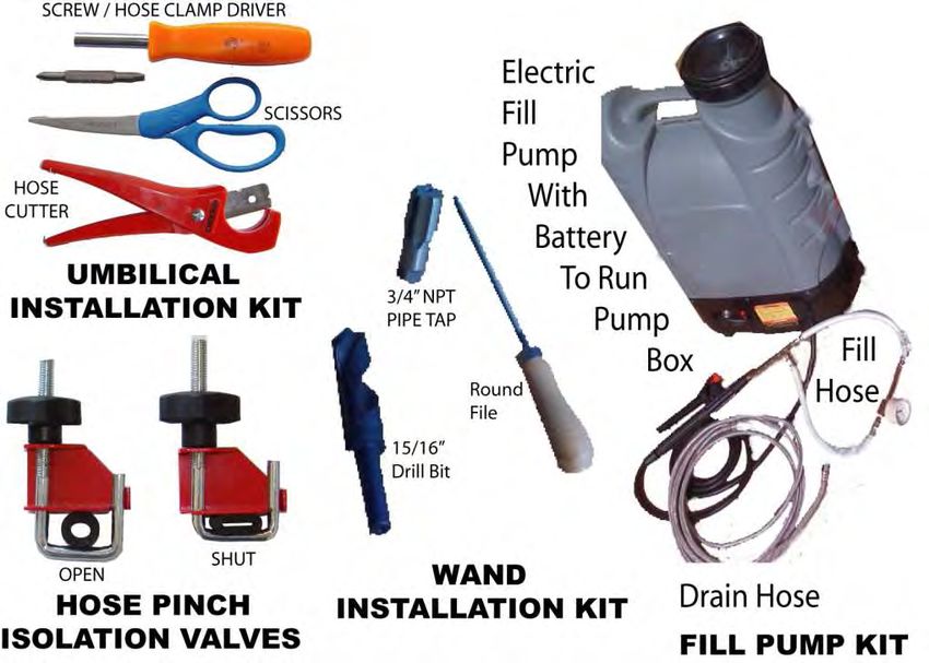
Revision 7                              Solar Six PackTM             Butler Sun Solutions Inc.
August 2012                                                        www.butlersunsolutions.com

   •   100 feet of ⅜-inch rope for pitched roofs.
Supplies You May Need To Provide
   •   Some municipalities require a solar site shadowing survey, which requires a Solar
       Pathfinder or equivalent. Many regional rebate administering offices that require this
       will lend you a Solar Pathfinder.
   •   One gallon of propylene glycol antifreeze (e.g., Peak Sierra®, carried by NAPA Auto
       Parts stores). Antifreeze is normally not shipped with BSSI systems, so you must
       obtain it locally.
   •   New flexible hot water tank inlet and or outlet lines of appropriate length
   •   Teflon® pipe tape for threaded fittings
   •   Plastic or metal down spouts, including elbows and angles, to hide the umbilical in
       outside wall installations
   •   Black electrical tape
   •   Assorted nails and screws
   •   Roof patching mesh
   •   Standard roof jack flashing for 2” roof penetration
   •   Collector supporting and elevating hardware if needed
   •   ¼-20 hollow wall anchors to hold collector down on roof (Stainless Steel or corrosion
       resistant fasteners)
   •   Flange and pipe mounting hardware
   •   Caulking
           o Henry’s Roofing Tar in caulking tubes for roof penetration and fastener seals
           o GE Clear Silicone II or equivalent for caulking split pipe and fittings.

Generic Tools                                          •   A 15/16-inch drill bit if your hot
                                                           water fitting has an obstruction
                                                           below it.
   •   Compass or GPS receiver to act as a
       compass and to obtain the site                  •   3/4-inch NPT pipe tap
       Latitude                                        •   Adjustable wrenches, 8” and 14”.
   •   Level or level/inclinometer                     •   Wood hole saw, 2” diameter and
       combination to measure the collector                2.5” diameter
       tilt angle.                                     •   Rubber hose cutters
   •   Thin stick or measuring tape                    •   Indelible magic marker
   •   Milwaukee M-SpectorTM or                        •   Wood and metal files
       equivalent video probe system to                •   Skil® Saw
       inspect the sacrificial anode and look          •   Sawzall® Saber Saw
       into walls for wires and pipes.                 •   Electric drill ½-inch chuck capacity
   •   Pipe wrenches, 12”, 14”, 16”.                   •   Twist drill bits up to ½-inch.
                                                       •   Masonry/Tile drill bits
                                                           o 1 inch hammer drill quality
                                                               masonry bit or a 1 ⅛-inch
                                                               Tungsten Carbide Core Drill

All Rights Reserved                                                               Page 3 of 65
            Installation Manual: Solar Butler 1.2 Solar-Assisted Hot Water System
Revision 7 Solar Six PackTM Butler Sun Solutions Inc.
August 2012 www.butlersunsolutions.com
(Remington Edge Grit) if you are • Pencils and paper
removing roof tiles for flange • Putty knife
mounting • Wire cutter and stripper
o ¾-inch Hammer drill quality • Volt-Ohm meter
masonry bit if you are leaving • Calculator
roof tiles in place and using • Dremel® tool with abrasive bits
hollow wall anchors
• 12VDC, 2A power supply to power
• Hammer PV-powered circulation pump if sun
• Tin Snips is not shining during installation
• Measuring tape, 20 to 50-foot length (PV-powered systems only)
• Plastic bottle, empty, 1 gallon, for
• Pliers, including Channel Locks® mixing antifreeze (Note: dispose of
and Vise Grips® properly after use)
• Screw drivers, straight blade and • Rags for clean up
Phillips • Broom and dust pan
• Caulking gun • Portable shop vacuum cleaner
• Matte knife and blades
Special Tools
The following special tools have been found to make the installation job go faster and easier.
Some are supplied with our system kits (e.g., the fill/flush tubes), and others are useful for
professionals doing many installations. Figure 2 shows some of these tools.
1. Battery Operated Filling Pump System with battery output to run pump to check system
circulation, and ¼-inch OD plastic fill tube to go from flush valve to filling pump
2. Hose to connect to a clean source of water for flushing out the system (NOTE: NOT THE
HOT WATER TANK DRAIN); female hose fitting on one end, ¼ inch compression on
the other (provided with system kits)
3. ¼-inch OD plastic drain tube about six feet long to go from fill/drain valve to bucket
(provided with system kits)
4. Combination screwdriver for tightening hose clamps
5. Digital volt meter, preferably with a thermocouple to measure temperature.
6. Rat tail file.
7. Pinch-off valves for rubber hose (used to seal hose ends for maintenance activities)
8. Rubber hose cutters or scissors.
All Rights Reserved Page 2 of 65
Installation Manual: Solar Butler 1.2 Solar-Assisted Hot Water SystemRevision 7 Solar Six PackTM Butler Sun Solutions Inc.
August 2012 www.butlersunsolutions.com
Figure 1 Special Tools to Speed Wand and Rubber Hose Installation
Do’s and Don’ts (What Your Mother Never Told You About
Solar Hot Water Installation!!)
1. Don’t open the SPOC™ and play with the radiator cap; it is inspected and installed at the
factory. To check the fluid level or fill the reservoir, open the cap with the float switch.
Or, pump fluid into the system from the pump station using a manual or powered pump.
2. Don’t connect flushing hose to the hot water tank drain valve. This can puts debris,
which will plug the Wand, into the closed solar loop. Use only a clean water source.
3. Do remember, if you did not wire out the top element push button reset on an electric tank,
to tell the customer that the high limit switch may trip during sunny weather especially if
they are away from home for several days. The limit must be manually reset or they may
have no hot water after a string of cloudy days.
4. Do remember to set the tank top safety snap switch, thermostat to 185ºF or higher. Lower
temperature push button resets must be replaced with higher temperature ones or wired out
based on local codes, with homeowner’s consent.
5. Do leave the upper thermostat setting alone; the customer will complain if you have several
cloudy days and his hot water is not hot enough.
6. Do remember to set the gas hot water tank temperature at 120ºF, just above warm.
7. Do check system operation by reading the temperature gauge at mid-day (e.g., between 10
AM and 2 PM) when the sun is out. The power and pump LED’s should be on and the
temperature should be above 120ºF.
8. Don’t forget to tell the customer that their new anti-scald valve may lower the temperature
of hot water at the faucets.
All Rights Reserved Page 3 of 65
Installation Manual: Solar Butler 1.2 Solar-Assisted Hot Water SystemRevision 7 Solar Six PackTM Butler Sun Solutions Inc.
August 2012 www.butlersunsolutions.com
9. Don’t panic when you turn on the gas burner in a newly filled old tank or a new tank full of
cold water and you hear dripping on the burner assembly that sizzles and makes you think
the tank is leaking. It is just condensation of water out of the gas combustion products and
will stop when the tank gets hot.
10. Don’t allow the customer to turn up the tank temperature setting. This may cause the tank
to overheat and shut down the solar system. The anti-scald mixing valve should keep the
tap temperature constant no matter how hot the tank gets.
11. Do tell the customers that, if they want hotter water, they should set the mixing valve
temperature higher.
12. Do tell the customer that because the SPOC™ Overflow is full, some fluid may spill on the
roof during the first few weeks of operation.
13. Do tell the customer that, if the pump shuts off under full sunlight, he may hear a bumping
noise on the roof. This is normal. If the customer hears this bumping noise his water tank
back-up temperature may be set too high.
14. Do remember to tell your gas hot water heater customers that tank overheating can melt the
fusible link in their gas burner regulating valve. If this happens the valve will need to be
replaced or the fusible link function restored with a similar fusible link or limit switch. It
has only happened to us on one out of 600 systems, but be warned.
Hazards of All Types
As a do-it-yourselfer, you must be comfortable assuming and mitigating the risks identified
below. If you don’t feel qualified to assume these risks, we recommend that you hire a licensed
contractor who is experienced with roof mounted solar installations.
Drinking Water Contamination Hazard
The system is designed to prevent cross-contamination of the heat exchanger fluid with potable
water. The Solar Wand™ is a double-walled heat exchanger.
CAUTION: If water or heat exchanger fluid begins leaking from the top of
the heat exchanger Wand, it means corrosion has breached a heat exchanger
wall. Even though one wall is still intact, the heat exchanger should be
removed immediately and replaced with a new one as soon as possible.
Hot Water Scalding Hazard
Hot water can scald you. Hot water can also be under pressure and squirt out. Wear leather
gloves to protect your hands and safety glasses or a face shield to protect your face when
opening the Hot Water Tank Drain Valve and removing tank inlet or outlet fittings.
CAUTION: BEFORE LOOSENING ANY PIPE CONNECTIONS NEAR
THE HOT WATER TANK ALWAYS TURN OFF THE POWER AND/OR
GAS TO THE HOT WATER TANK TO ALLOW THE WATER TO COOL
DOWN AND TO RELIEVE THE TANK’S INTERNAL PRESSURE.
ADDITIONALLY BE SURE TO ALWAYS ATTACH A HOSE TO THE
DRAIN VALVE BEFORE OPENING IT.
All Rights Reserved Page 4 of 65
Installation Manual: Solar Butler 1.2 Solar-Assisted Hot Water SystemRevision 7 Solar Six PackTM Butler Sun Solutions Inc.
August 2012 www.butlersunsolutions.com
Ladder Hazard
Working on ladders is dangerous. Be sure that the ladder is properly placed and seated on the
ground. Do not lean back while moving collectors from the ground to roof. Do not over-reach
when running the fluid lines and umbilical. It is safest to have someone hold the ladder.
Falling Hazard
Working on roofs is extremely dangerous, and sure footing is required. Be sure to wear rubber-
soled shoes that cover your entire foot and are laced snugly. (Do not wear sandals or flip flops
on roofs.) Falling to the ground can be deadly. Be sure to stay a safe distance from the roof
edge. Do not use collectors as a support, even if they are attached to the roof – solar collectors
are not designed to be handrails. Plan the installation to place the collector on the roof safely
away from the roof edges. Safety ropes and harnesses are required for steep roofs and can
add safety on low pitch roofs. A solar installer fell off a roof in
2009 and died. This is the most deadly hazard; harnesses and ropes save lives.
Electrical Shock and Fire Hazards
Do not drill into the roof or walls until you have looked or verified using a stud, wire & pipe
finder that no pipes or electric lines are in your drill path. If you have any doubts about what is
inside the wall or roof, drill a small pilot hole and look or probe to be sure that it is safe to drill.
Drilling into electric lines, water pipes or gas pipes can be both dangerous and costly to repair.
Electrocution Hazards
Beware of electric shock hazards. Do not stand in water and touch electrical components. Test
the 3-pronged polarized, electrical outlet you intend to use for the controller. Using an electrical
outlet polarity and fault detector, check to be sure that the hot, neutral and ground are properly
wired. A ground fault circuit interrupter (GFCI) outlet is recommended to reduce the possibility
of electrical shock. Plug-in ground fault interrupters do not require an electrician and provide the
same electrical shock protection.
All Rights Reserved Page 5 of 65
Installation Manual: Solar Butler 1.2 Solar-Assisted Hot Water SystemRevision 7 Solar Six PackTM Butler Sun Solutions Inc.
August 2012 www.butlersunsolutions.com
STEP 1. Planning The Installation
Figure 1.1 Good Installation Planning Results in A Clean, Professional Installation
1.1 Installation Overview
The following sections outline a recommended procedure for system installation – those skilled
in solar installation may have better or faster ways of achieving the same professional
installation. But the described procedures have been found to be an effective way of installing
the solar system without being exposed to excessive risks. Safety tips are included, but if there is
any question of risk, hire a certified contractor with roof expertise. Always use caution when
working around ladders, on roofs and near hot pressurized water. A professional installation will
serve you well for years to come.
Figure 1.2 provides an overview of the system and its major components for reference purposes.
The system has been engineered for easy installation. The patented Solar Wand™ is a double-
walled heat exchanger that is the heart of the system. Figure 1.3 provides a cut away view of the
Wand. The Solar Wand™ screws into a standard hot water tank, converting it into an efficient,
low-cost solar storage tank. The Wand connects to a pump station which contains system
charging valves, back flow prevention valve, electronic controls and temperature and pressure
gauges. The solar pump and control system are powered by a photovoltaic panel on the roof.
All Rights Reserved Page 6 of 65
Installation Manual: Solar Butler 1.2 Solar-Assisted Hot Water SystemRevision 7 Solar Six PackTM Butler Sun Solutions Inc.
August 2012 www.butlersunsolutions.com
Both flat plate and evacuated tubes work well with our system. The collectors are generally
installed on a rooftop or other exposed location. A flexible umbilical containing rubber hoses and
electrical cables connects the collectors to the pump box. After installation, aluminum cladding
is used to cover and protect exposed portions of the umbilical.
Figure 1.2 BSSI Solar Six Pack™ Solar Hot Water System
All Rights Reserved Page 7 of 65
Installation Manual: Solar Butler 1.2 Solar-Assisted Hot Water SystemRevision 7 Solar Six PackTM Butler Sun Solutions Inc.
August 2012 www.butlersunsolutions.com
Figure 1.3 Solar Wand Heat Exchanger, US Patent #6,837,303 B2
The function and operation of each component identified in Figure 1.2 is described in the
sections detailing the installation of each “Can” of the Solar Six Pack. So, for example, the
installations instructions for the SPOC™ (Can 2) show how the Self-Pressurizing Unit functions
to displace air from the fluid loop and protect the solar collectors from stagnation.
1.2 Planning the Installation
This STEP requires you to locate your hot water tank and determine the location where you want
the solar collectors to be installed. The collector is supplied with a 25-foot umbilical length to
reach from the hot water tank to the solar collector. More umbilical can be purchased if
necessary, but generally the collectors should be located as close to the hot water heater as
possible. NOTE: THE TOP OF THE COLLECTOR NEEDS TO BE ABOVE THE ROOF
PENETRATION, SO THAT THE TOP OF THE COLLECTOR IS THE HIGHEST
POINT IN THE FLUID HEAT TRANSFER LOOP (see Figure 1.1.)
1.2.1 Determine True South
Ideally, a collector should face True South (plus or minus 20°). There are several methods that
can be used to determine True South. A compass points to Magnetic North, so you must use a
declination value from a map or declination table to correct a compass reading to get True South.
Many GPS systems include a compass feature that may also be used to find True South. If you
do not have a compass or GPS, you may note that the shadow of a vertical stick or surface will
point to True North at solar noon, and True South is 180º from True North. Internet mapping
sites such as Google Maps can be used to estimate the orientation of buildings and their roofs.
Finally, note that urban street grids are often laid out on True North-South lines, and can be used
for reference.
All Rights Reserved Page 8 of 65
Installation Manual: Solar Butler 1.2 Solar-Assisted Hot Water SystemRevision 7 Solar Six PackTM Butler Sun Solutions Inc.
August 2012 www.butlersunsolutions.com
1.2.2 Choose Collector Tilt Angle
Collectors may be tilted at the latitude angle plus 15° for best winter operation and latitude
minus 15o for best summer performance. Tilting at the latitude angle yields the best year round
performance. HINT: SOLAR COLLECTORS ARE OFTEN PLACED PARALLEL TO A
SLOPING BUILDING ROOF. THIS IS MORE AESTHETICALLY PLEASING AND
MAY RESULT IN ONLY A SMALL (E.G., 10%) PENALTY IN ANNUAL
PERFORMANCE.
The approximate latitude of your site can be found on the Internet (e.g., www.mapquest.com) or
in your local paper. The latitudes of some selected U.S. cities are presented in Table 1.1 for
reference. (HINT: Look at other solar collectors in your area, see how they are oriented to South
and elevated for latitude) A GPS will also provide the exact latitude of a site. Our website
(www.butlersunsolutions.com) includes the complete Department of Housing and Urban
Development (HUD) Manual for solar system installation. The report includes a solar siting
template to show the effects of shadowing from trees or nearby buildings, a magnetic declination
map, and other useful information about system siting.
Table 1.1 Approximate Latitudes of Selected U.S. Cities
City (arranged by decreasing latitude) Latitude (all North)
Anchorage, AK 62°
Juneau, AK 58°
Seattle, WA 47.5°
Portland, OR; Minneapolis, MN; Bangor ME 45°
Buffalo, NY 43°
Chicago, IL; Boston, MA; Detroit, MI 42°
Denver, CO; Indianapolis, IN; Philadelphia, PA 40°
Kansas City, MO; St. Louis, MO; Washington, 39°
DC; Cincinnati, OH
Reno, NV 39.5°
San Francisco, CA; Sacramento, CA 38°
Nashville, TN 36°
Albuquerque, NM; Memphis, TN 35°
Los Angeles, CA 34°
Phoenix, AZ; Charleston, SC 33°
San Diego, CA; Savannah, GA 32°
Houston, TX; New Orleans, LA; Jacksonville, FL 30°
Tampa, FL 28°
Brownsville, TX; Miami, FL 26°
Honolulu, HI 21°
Hilo, HI 20°
1.3 Collector Location and Orientation
Horizontal (“landscape”) mounting will minimize the height the collector rises above the roof
when it is tilted up above the roof slope. Look for a location on the roof which will not be
shaded by trees, other parts of the building, or other buildings. The solar collector should not be
All Rights Reserved Page 9 of 65
Installation Manual: Solar Butler 1.2 Solar-Assisted Hot Water SystemRevision 7 Solar Six PackTM Butler Sun Solutions Inc.
August 2012 www.butlersunsolutions.com
shaded between the hours of 8AM to 4PM. For best year-round performance, the tilt should be
equal to the latitude angle. Architecturally it may be desirable to place the collector flat on a
South-facing roof slope. Placed flat on the roof it will look like a skylight and blend into the roof
better. The appearance may be much improved and the performance loss may be minimal.
The Solar Orientation Factor (SOF) is shown in Figure 1.4. This is a factor that shows how the
performance of a solar collection system varies with the orientation of the collector. The
example shown is San Diego, CA (approximately 30° latitude), and shows that a system can
operate with less than a 10% reduction in system performance (i.e., SOF>0.9) over a range of
tilts up to about 60 degrees facing South, or with azimuth values ranging up to 60-80 degrees
away from True South.
Figure 1.4 Solar Orientation Factor for San Diego, CA
1.4 Collector Selection
What collector is right for my location? We use some simple rules of thumb, based on the SRCC
data plotted in Figure 1.5. The heat exchange area of the Solar Wand™ is only two square feet,
less than some other systems with built-in heat exchangers. Because the area is smaller, the solar
system must run hotter to transfer the same amount of heat from the solar loop into the hot water
tank. The higher loop temperature means that the solar collector will lose more heat to the
environment. Hence, if you live above 40˚ North Latitude in a place that gets really cold in
winter, you might want to consider a double-glazed flat plate or an evacuated tube collector. For
most of the rest of the United States, single-glazed flat plate collectors work well with our Solar
Six PackTM System. There is a small (about 4%) system performance loss due to the higher loop
temperatures, but this is overwhelmed by the installed cost savings.
All Rights Reserved Page 10 of 65
Installation Manual: Solar Butler 1.2 Solar-Assisted Hot Water SystemRevision 7 Solar Six PackTM Butler Sun Solutions Inc.
August 2012 www.butlersunsolutions.com
Figure 1.5 Effect of HX Surface Area on Collector Performance
1.5 Routing the Umbilical
Place the solar collectors so the umbilical can connect from the tank to the solar collectors via a
reasonable path. The umbilical can go through the roof into an attic or crawl space over the
house or the garage, then to the top of the hot water tank. The umbilical can also be routed off
the edge of the roof and down the outside of the house. It can be disguised as a downspout by
putting it inside of a downspout painted to match the house or other downspouts on the house.
All Rights Reserved Page 11 of 65
Installation Manual: Solar Butler 1.2 Solar-Assisted Hot Water SystemRevision 7 Solar Six PackTM Butler Sun Solutions Inc.
August 2012 www.butlersunsolutions.com
STEP 2. Installing the Solar Collectors
(Can 1)
Mounting of the solar collectors is specific to the type and orientation of the collector relative to
the roof. Each manufacturer has their own specifications and mounting approaches, so this
manual does not present comprehensive information on collector mounts. Figure 2.1 shows a
collector attachment method we have used for concrete tile roofs. A standard ½” or ¾” pipe
flange is bolted to the plywood deck, a hole cut in the tile over it, and a galvanized pipe nipple is
threaded into the flange after the tile is put back in position. This forms a solid but inexpensive
collector mount. Note that the hole should fall on the top of the tile curvature.
Figure 2.1 STEP 2 -Collector Mounting
Mounting on asphalt shingle roofs is very simple, requiring only that care be taken to locate the
studs and flashing and roofing sealant be used to prevent leaks.
2.1 Collector Orientation Flow Path Do’s &Don’ts
The buoyancy of hot fluid in the solar collectors helps the PV powered pump circulate the
antifreeze fluid. The configurations that we know work very well with parallel tube collector
designs are shown in Figure 2.2. The importance of the collector orientation is to allow steam to
escape easily to the SPOC™ at the top of the collector during stagnation.
All Rights Reserved Page 12 of 65
Installation Manual: Solar Butler 1.2 Solar-Assisted Hot Water SystemRevision 7 Solar Six PackTM Butler Sun Solutions Inc.
August 2012 www.butlersunsolutions.com
Figure 2.2 Collector Orientations for Steam Escape
Serpentine solar collector should only be mounted in the “landscape” orientation as shown in
Figure 2.2 illustration 1, since steam will not escape from Portrait Oriented solar collectors
(Figure 2.2 illustration 4). The collectors should be installed so the long serpentine tubes are
level.
For collectors with headers and parallel riser tubes, the “portrait” orientation is recommended
(Figure 2.2 illustration 3) so the flow goes from bottom to top and tends to sweep the steam
into the upper header. That header should be tilted about 2 degrees so the steam will go to the
highest point, where the SPOC™ is connected. With “landscape” orientations of parallel tube
collectors (Figure 2.2 illustration 2), caution must be exercised to allow buoyancy to get the
steam to the highest point. Since the liquid flow is horizontal, the collector must be both tilted
up to the South (e.g., by 18° or more), and pitched up so the outlet end is at least 4 inches above
the inlet end of an 8-foot long collector (6 inches for a 10-foot long collector).
CAUTION: THE COLLECTOR MUST BE TILTED UP A MINIMUM OF
18.5o (4-IN-12 PITCH) TO 26.5o (6-IN-12 PITCH) ANGLE SO THE STEAM
CAN MOVE THROUGH THE COLLECTOR FLOW PATH TO THE
SELF-PRESSURIZING UNIT WITHOUT BEING TRAPPED.
EVACUATED TUBE COLLECTORS WITH HEAT PIPES MUST BE
TILTED AT LEAST 18.5o AND PREFERABLY 30o ABOVE
HORIZONTAL TO ALLOW GRAVITY TO RETURN THE HEAT PIPE
FLUID TO THE BOTTOM OF THE COLLECTOR.
2.2 Serpentine Flow Solar Collectors
The ACR Skyline module is unique to the solar industry. The 20” x 3” x 72” size and light
weight (20 pounds) allow the modules to be shipped by UPS and FedEx. The internal plumbing
configuration allows the 10-square-foot building blocks to be assembled into arrays, since they
can be stacked up or placed end to end. The shape of the row-by-column array can be matched
to the area available on the roof. Larger water tanks need more modules, so the size of the solar
collector array can be matched to the size of the hot water storage tank. The overview in Figure
2.3 shows how 4 collectors can be used to form a single column or a 2 x 2 array. A photo of four
modules arranged in a vertical column is also shown in the figure.
All Rights Reserved Page 13 of 65
Installation Manual: Solar Butler 1.2 Solar-Assisted Hot Water SystemRevision 7 Solar Six PackTM Butler Sun Solutions Inc.
August 2012 www.butlersunsolutions.com
Figure 2.3 ACR (Solar Roofs.com) Solar Collector Arrangements and Example of a
Vertical Column Installation
2.3 Parallel Flow Solar Collectors
The inlet and outlet fittings are specifically designed to for parallel flow collectors in either
landscape or portrait orientations. The adapters for screw-on collectors are shown on the left half
of Figure 2.4, while the solder-on adapters are shown in the right half. Connecting the hoses to
these adapters properly is necessary to having the system perform well. The outlet adapters have
two separate tubes coming out of them. The one labeled SPOC™ is the steam outlet, and the one
that goes 4 to 6 inches down into the header of the collector is the fluid outlet. This outlet
adapter separates the steam from the liquid. Make sure you have the hose connections correct.
Figure 2.4 Parallel Flow Collector Connections
2.4 Evacuated Tube Collectors
The picture in Figure 2.5 shows a properly mounted evacuated tube system. Note that the
SPOC™ self-pressurizing unit is mounted above the manifold, where the heat pipes from the
tubes transfer their heat to the antifreeze fluid. The tube heat pipes slide into the manifold and
must be coated with a heat transfer grease to assure good thermal contact. Heat pipe evacuated
tubes should not be tilted less than 20 degrees above horizontal. Note that the upper rear
brackets have been lengthened to achieve a higher tilt angle than the roof, which was 18.5o (4-in-
12 pitch) degrees above horizontal.
All Rights Reserved Page 14 of 65
Installation Manual: Solar Butler 1.2 Solar-Assisted Hot Water SystemRevision 7 Solar Six PackTM Butler Sun Solutions Inc.
August 2012 www.butlersunsolutions.com
Figure 2.5 Properly Mounted Evacuated Tube System
2.5 Mounting Thermal Collectors
The key to successful roof mounting is to provide a strong and stable attachment for the
collectors while not creating leaks in the roof. The collector can be flashed into the roof using
standard flashing techniques, or mounted on collector racks made for this purpose. Our website
(www.butlersunsolutions.com) includes the Department of Housing and Urban Development
(HUD) manual for solar system installation. This report includes roof mounting procedures and
illustrations showing how to secure solar collectors to the roof. It also discusses wind loading
and how to brace collectors to withstand 100 mile-per-hour sustained wind loads, with peak
winds reaching 125 miles per hour. It is important to use corrosion resistant fasteners such as
stainless steel if you are in a wet or salt air environment. Various roof mounting methods are
shown in Table 2.1.
IMPORTANT: BE SURE TO CONSULT YOUR LOCAL CITY OR
COUNTY BUILDING DEPARTMENT TO ENSURE YOU ARE IN
COMPLIANCE WITH ALL PERMITS, REQUIREMENTS, AND STATE
AND LOCAL CODES AND PRACTICES.
All Rights Reserved Page 15 of 65
Installation Manual: Solar Butler 1.2 Solar-Assisted Hot Water SystemYou can also read