MINI ES Battery Base Installation Manual - MINIES-B3-R1 - Ultra Green Energy
←
→
Page content transcription
If your browser does not render page correctly, please read the page content below
MINI ES Battery Base
  Installation Manual
             MINIES-B3-R1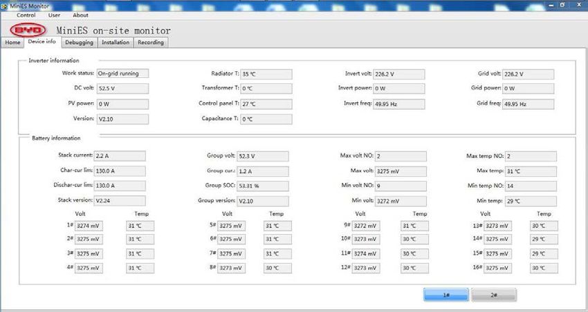
Content
1. Introduction .................................................................................................................................1
     1.1 Brief description ...............................................................................................................1
     1.2 Disoperation predictable .................................................................................................2
     1.3 About this manual ............................................................................................................3
     1.4 Abbreviations ....................................................................................................................4
     1.5 Specification .....................................................................................................................4
2. Safety Requirements .................................................................................................................6
     2.1 Responsibilities of the installer ......................................................................................6
     2.2 Qualified electrician .........................................................................................................6
     2.3 Requirements for the installation location ....................................................................8
     2.4 Safety signs on the device........................................................................................... 10
     2.5 Basic safety information ............................................................................................... 10
     2.6 Other safety instructions .............................................................................................. 13
3. Transporting to the Installation Location ............................................................................. 15
4. Installation ................................................................................................................................ 15
     4.1 Safety instructions ........................................................................................................ 15
     4.2 Installation site safety check ....................................................................................... 16
     4.3 Check the package ....................................................................................................... 17
     4.4 Remove the enclosure ................................................................................................. 17
     4.5 MINIES battery base fixing .......................................................................................... 17
     4.6 Wiring.............................................................................................................................. 23
     4.7. Trial operation of device ............................................................................................. 31
     4.8 Reassemble the MINI ES ............................................................................................ 39
     4.9 Attached list ................................................................................................................... 47
5. Daily Maintenance Methods .................................................................................................. 48
     5.1 Common faults .............................................................................................................. 48
     5.2 Daily maintenance ........................................................................................................ 48
6. About BYD ............................................................................................................................... 49

                                                                         I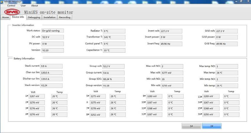
1. Introduction
Dear customer:
Thank you very much for purchasing the MINI energy storage base supplied by BYD Auto
Industry Company Limited. We sincerely believe that our products meet your needs. We
value your feedback on the product performance, appearance and function and we strive
to continually improve our product.

1.1 Brief description
To meet the 3kW/3kWh household energy storage system (MINI ES) capacity expansion
demand, BYD integrated years of development and operation experience launched the
3kW/6.3kWh household energy storage solution: [3kW/3kWh MINI ES] +3.3kWh battery
base system.
The system highlighted the overall technology advantages of intellectualization and
integration, set of BYD Iron-Phosphate Battery, PCS, distributed BMS, monitoring system
and other advanced technology, realize remote monitoring through the APP (support iOS
and Android system). With high reliability, high safety, high efficiency, energy conservation
and environmental protection, etc. Small volume, light weight, easy installation and
maintenance.

                         figure1. Installation effect drawing
Note: MINIES 3.3kWh battery base is used together with MINIES P30B3-AU-R2, it can be
extended to 3kW/6.3kWh MINIES system.

                                             1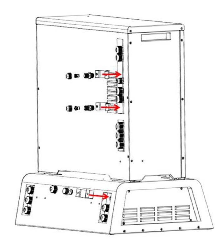
Functions
Functions of the MINI ES battery base are shown as below:
When MINIES 3.3kWh battery base is used with 3kW/3kWh MINIES together, it can
extend to be 3kW/6.3kWh MINIES system.
When grid power is unavailable, battery base will cooperate with MINIES P30B3-AU-
R2 supply power to essential loads, such as computer, phone, TV general lighting, etc.
1.2 Disoperation predictable
Battery
Battery Parameters
Nominal Voltage 25.6V
Capacity 75Ah
Energy 1.92Wh
Mechanical characteristics
Thickness 139±2mm
Width 189±2mm
Length 458.5±2mm
Weight <20Kg
Electrical characteristics
Charge Method CC/CV/CP
Charge Current 37.5A (Standard)
75A (Max. Continue Current @ 25℃)
Charge Cut-off Voltage 3.60V/Cell
Discharge Method CC/CV/CP
Discharge Cut-off Voltage 2.80V/Cell
Discharge Current 37.5A (Standard)
75A (Max. Continue Current @ 25°C)
Any operation of the storage system beyond the description of correct operation may be
considered as improper use.
The device shall not be operated:
In rooms smaller than 8m3
In rooms that contains flammable materials, fire, or in explosive atmospheres
In insufficient ventilated rooms under 8-25 m3
In areas with ambient temperature below0℃ above +40℃
2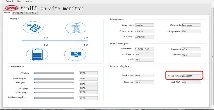
Use the battery not authorized by BYD
In a damaged house
With any batteries other than approved by BYD
With defective cables
With parts that are clearly defective or damaged
1.3 About this manual
Declaration
This manual is applicable to the MINI ES battery base (MINI ES-B3-R1). Mainly
presentation the functions and attentions in transportation, assembling, installation,
commissioning and using of product.
This manual is applicable to transportation, assembling, installation and commissioning.
Target Readership
This manual is intended to be used by the accredited installer.
Manual keeping
This manual contains important information. Please read this manual carefully before
operating and servicing the MINI ES battery base.
Please strictly follow the manual instructions when operating the system, otherwise it may
cause the product to fail or cause personnel casualty or property loss.
This manual shall be stored and safely be accessible on site to the installer and service
technician at any time.
Alarm signs
Please keep several types of safety alarm signs in mind. Familiarize yourself with the
messages and the importance of the various signals as explained.
Warning instructions identify safety information, which include the following:
Warning sign
Instructions to denote the level of risk
Details of the nature and source of the risk
Details of the potential risk if the warning instructions are disregarded
Risk management to prevent the danger or personnel casualty or material damage
The warning instructions are defined according to the following level of hazards
DANGER!
Denotes an extraordinarily hazardous situation
This warning symbol indicates an immediate danger, which can lead to severe
injury or death.
3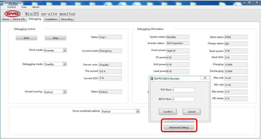
WARNING!

  Denotes a very dangerous situation
  This warning symbol indicates a potentially dangerous situation, which could lead
  to severe injury or death.

                CAUTION!

  Denotes a dangerous situation
  This warning symbol indicates a potentially dangerous situation, which could lead
  to minor injury.

                NOTICE!

  Denotes a risk of material damage
  This warning symbol indicates a situation that could lead to material   damage.

1.4 Abbreviations
Abbreviation                Description
APP                         Application software
CT                          Current transducer
DOD                         Depth Of Discharge
SOC                         State of Charge

1.5 Specification
 NO.            Type                  MINIES-B3-R1                        Remark
                                   Battery Parameter
                                                                 Voltage Range:
     1     Rated Voltage                  51.2Vdc
                                                                 44.8Vdc~57.6Vdc
     2      Battery Type                  LiFePO4
           Max discharge
     3                                    3.7KW
              power
           Max discharge
     4                                     65A
              current

                                           4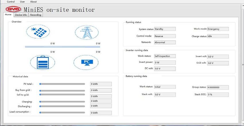
NO.        Type                 MINIES-B3-R1                Remark
        Max charge
 5                                  3.7KW
          power
       Max charge
 6                                   65A
        current
       Min charge
 7                                       2A
         current
        Max output
 8      short circuit      247.5Ad.c(peak),1.93ms
          current
         Battery                                        At +10℃~+30℃,
 9                             3.3kWh DC side
         Capacity                                       discharge at 0.5C
        Overvoltage
10                                       Ⅱ
      categorles OVC
                             Protect Function
11                          Short Circuit Protection
12                       Under-temperature Protection
13                       Over-temperature Protection
           BMS
14                         Under-voltage Protection
15                         Over-voltage Protection
16                         Over-current Protection
                             Other Parameter
        Operation
17                                 5%~95%
        Humidity
18        Altitude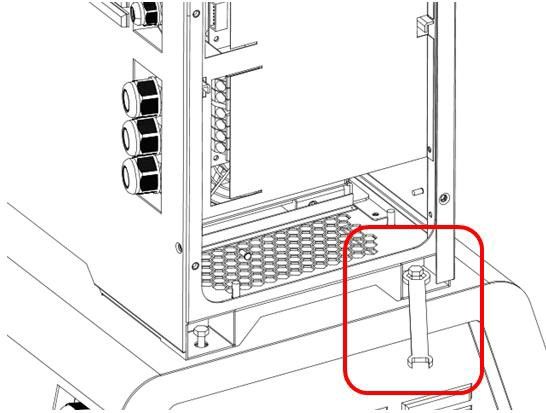
NO. Type MINIES-B3-R1 Remark
Usage Indoor(No Condensation,
30
Environment Freeze, Direct Sunlight)
Design Standard
Battery
31 UN38.3, AND IEC 62040
Standard
2. Safety Requirements
2.1 Responsibilities of the installer
The installer must ensure that:
The safety protection equipment of the system is fully functioning
Any unclear warning and safety signage on the device shall be replaced immediately
Make sure there is no flammable items stored near the device
The device shall not be covered at any time
The device is required to be placed on a surface that can support the full weight of the
unit
Transportation, assembling, installation and commissioning of the device shall be
carried out by authorized personnel only
Transportation, assembling, installation and commissioning of the device shall be
carried out only under the specified conditions
The authorized installer shall be capable of evaluating the potential risk
Only authorized and trained electricians can perform installation, commissioning, and
change the settings and connect to the Router
Before installation and operation, any potential hazards shall be identified and the
necessary risk management should be applied onsite.
This manual and safety instructions shall be read and understood by the installer
before starting installation
Changes are not allowed to the software, housing and components of the device
without the manufacturer's approval. Otherwise, the liability and warranty may be
invalid.
The unit is not allowed to be opened except by authorized and trained electricians. If
the seal is broken due to unauthorized modification of the components, the warranty
will be invalid.
All operators of the energy storage system shall follow the user manual, installation and
service manuals and quality guarantee. Any damage to equipment caused by ignoring and
misreading the user manual, installation and service manuals and quality guarantee will
invalidate the product warranty.
2.2 Qualified electrician
Qualification
A qualified electrician is a person who possesses the required knowledge, technical
6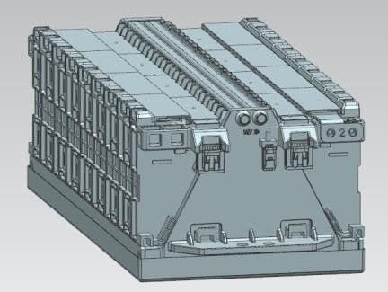
training and experience, to conduct the following:
Setting up, activating, deactivating, disconnecting, grounding, short-circuiting and
repairing electrical circuits and devices.
Standard maintenance and use of protective devices defined in the safety standards.
Administering first-aid to injured parties.
Compliance with local regulations, applicable standards and directives.
Battery Maintenance
When the device is not used for a long time, discharge the battery to between 45%
and 60% of the battery capacity, and disconnect the battery output to avoid the battery
power being emptied;
When the device is not used for a long time, it is recommended to charge the battery
once every six months to ensure that the battery can work normally.
Ensure reliable grounding.
Battery maintenance must be carried out by professionals or under their direction;
When replacing the battery, use the same type and number of batteries or battery
packs;
Warning: Do not throw the battery into a fire. The battery may explode;
Warning: Do not open or damage the battery. The electrolyte flowing out of the battery
is harmful to the skin and eyes. The electrolyte may also be toxic;
Warning: The battery may cause a shock hazard and a large short-circuit current.
When handling the battery, pay attention to the following aspects:
a) Remove watches, rings and other metal products;
b) Use a tool with an insulated handle;
c) Wear rubber gloves and shoes;
d) Do not place tools or metal parts on the battery;
e) Disconnect the charging power supply before disassembling the battery terminal
block;
f) Pay attention to whether the battery is inadvertently grounded. If you find that
thebattery has been accidentally grounded, remove the power supply from theground.
Touching any part of the grounded battery can cause an electric shock. Disconnecting
ground during installation and maintenance reduces the probability of electric shock
(applicable to equipment without a grounded power supply and remote battery power).
g) Do not touch the battery pack with wet hands.
h) Do not crush, drop or puncture the battery.
i) Always dispose of the batteries according to local safety regulations.
j) Store and recharge battery in a manner in accordance with this user manual.
k) The charging circuit of inverter shall be DVC A, and the output circuit needs to be
isolated from high voltage bus.
l) Do not reverse battery polarity
m) When storing or transporting the battery, do not stack the battery without protective
packaging
n) Packaged batteries should not be stacked more than specified number stipulated
7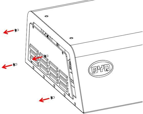
on the package.
All operators of the energy storage system shall follow the user manual, installation
and service manuals and quality guarantee. Any damage to equipment caused by
ignoring and misreading the user manual, installation and service manuals and quality
guarantee will invalidate the product warranty.
Responsibilities
The electrician shall ensure that:
The general information, step-by-step instructions and the safety instructions
regarding assembling and installation are read and followed at all times
Neither the physical size nor the rated current value of fuses can be changed
Before any electrical work is performed, ensure that equipment completely without
electricity and suitable measuring equipment shall be used to ensure that the device
is in accordance with applicable directives
The device shall never be opened during operation
2.3 Requirements for the installation location
Always select a suitable location before installation. The installer shall ensure that the
installation location meets the following conditions:
NOTICE!
Material damage due to inadequate ventilation
Individual components is not cooling fully as inappropriate or clogged ventilation,
will case components aging in advance, this will produce irreversible damage to
the device. Ensure full air circulation during the closing operation.
• Sufficiently ventilate the installation room
• Install all components according to the instructions
• Do not stack anything on the device.
• Operate the device only when it is closed
The installation room environmental requirements
The room must be kept dry and enclosed.
Protected against penetrating water.
Remove irrelevant items.
Always install away from highly flammable (e.g. paper) or explosive materials (e.g.
fuel, paint)
Sufficient ventilation (max humidity of 95%)
When the system is running, it will produce a trace of noise, recommended do not
install in the bedroom and other living areas, better in the garage, storage room, tool
room and other areas where do not affect the users.
8Room size
Room no less than 8.00 m³.
Room from 8 to 25 m³: passive or active ventilation is required (at 8 m³: air exchange
rate is 12 m³/h).
Rooms larger than 25 m³: do not need separate ventilation.
Space required.
Min. base surface area is 2.00 m²
Min. height is 2.00 m
Min. depth is 2.00 m
Ceiling, ground and wall requirements
Ceiling made from non-flammable material
Ground capable of supporting the total weight of the device: 153kg (3kW/3kWh system
96kg, 3.3kWh battery base 57kg.)
Minimum clearance from the wall is 15 cm
figure2. Schematic diagram of the installation gap
Temperature and humidity requirements.
Room temperature of 0℃ to + 40℃
Max. humidity of 95%
Access authority
Children shall be accompanied by an adult if they are in the installation room
Children shall not operate the storage system
9Protection grade
IP32
2.4 Safety signs on the device
Item Description
Be aware of dangerous voltage/ electric shock
ISO 7000-1641
The product should not be disposed of together with household
waste at the end of its life.Please send it to a proper institution for
recycle and reuse
Point of connection for grounding protection
Hot surface
IEC 60417-5019(2011-01)
IEC 60147-5018(2011-01)
Pass CE authentication
2.5 Basic safety information
This chapter contains the basic safety instructions. Failure to follow the safety instructions
in this manual can result in accidents which can lead to serious injury and/or death, as well
as serious components damage.
Risk of fatal injury: General
10DANGER!
Risk of fatal injury due to lack of assistance
In the event of an accident a second person can switch off the power supply and
provide assistance.
• Only perform the work if a secondary installer is presented.
DANGER!
Due to disregard of safety instructions
If the safety instructions and/or installation are not followed , the product may be
permanently damaged and electrical accidents with serious consequences may
occur.
• Follow the safety instructions
Risk of fatal injury: Inverter
DANGER!
Risk of fatal injury due to residual voltages
The inverter capacitors may still discharge even after the device is switched off.
• Ensure external and internal switches are disconnected.
• After switching off the device, always wait 10 minutes before direct contact with
the unit.
• Use a certified multimeter to check if the device is still energized in accordance
with applicable guidelines
DANGER!
Risk of fatal injury from arcing
Arcing may occur in the event of faults or if fuses and plugs are not properly
connected.
• Always use components in accordance with the instructions of the respective
manual
Risk of fatal injury: Battery
11DANGER!
Risk of injury due to electric shock
Batteries can generate significant amounts of short-circuit current due to incorrect
operation ,which can cause electric shock and lead to serious injury and/or death.
While working with batteries, always remove watches, rings and other metal
equipments.
Only use tools that have insulated handles
Do not place or store tools or other metal objects on the batteries
Always disconnect the charging and discharging source first before working on
the battery connections
Reconnect the unit only after comprehensive check of all connections and terminals,
ensure the wiring Is correct.
DANGER!
Risk of explosion due to using incompatible battery types
If other battery types not approved for the device are used, the existing and unapproved
batteries may explode.
• Only use batteries that have been approved by the manufacture
• Check with the manufacturer before installation
Risk of injury General
WARNING!
Risk of injury due to unauthorized installation
Installation and commissioning of this storage system requires BYD authorized
training and relevant accreditation.
Installation, cabling and commissioning must only be carried out by authorized,
trained electricians.
• The device operating temperature may reach up to 100℃, do not touch the hot
surface.
After switching off the device, you must wait for 10 minutes before touching any
components.
12WARNING!
Risk of injury due to heavy weight
The heavy weight of components may cause injury during installation,
disassembling, transportation.
• Transportation and installation requires a minimum of two people.
• Transport the device with appropriate lifting equipment.
WARNING!
Risk of injury due to incorrect installation procedure
If the sequence specified in the instructions is not followed during the installation of
the components, this can cause injury or material damage.
• Read the installation manual carefully and follow the installation procedure.
WARNING!
Risk of injury due to sharp edges
The components have sharp edges, which can cause injury if they are not handled
carefully.
• Wear protective equipment.
• Install the system with a minimum of two people.
WARNING!
Risk of incorrect use of the batteries
Eye and skin injuries can be caused by opening or damaging the batteries.
Never open or damage the batteries
• Do not short-circuit the batteries
• Do not reverse the polarity of the batteries
• Do not overcharge the batteries
2.6 Other safety instructions
13WARNING!
• Climbing on the equipment is prohibited. Please do not pace accessories on or
inside the device.
• Decomposition, reconstruction, repair of equipment without the manufacture
permission is prohibited.
• Internal electrical maintenance of equipment by any non-professional is
prohibited. When maintenance is needed, please contact the authorised
provider.
• Blocking the ventilation of the device is prohibited.
• Do not put any objects inside the equipment.
• Do not touch, pull or cut off the internal cables coming from the device.
• Do not place heat source near the device (such as electric furnace and other
heating equipment).
• Do not wipe the device with a damp cloth or chemicals (such as detergent).
• Do not pull the power cord of the device.
• Do not set the device close to any high frequency machines, wireless machines,
radio, television or the electrical equipment which will disturb signals.
• Do not apply heavy impact or tilt the device.
• Do not spray any liquid on equipment.
• Do not install the device in areas with electrostatic charge or noise.
• The essential loads will experience a short period blackout (less than 5
seconds) when grid drop off before MINIES supplying power.
• Please do not connection medical equipment to essential loads as MINIES is
not a UPS device.
• When the device itself or parts are damaged, do not attempt to repair or move
the device, consult a suitably qualified installer.
NOTICE!
• Avoid direct contact with the device during severe weather condition.
• The device is prohibited to use for medical equipment.
• If equipment appears deformed, broken or has abnormal sounds or smells,
please contact BYD authorised service provider immediately.
• If equipment malfunctions or cannot run normally, please contact the authorised
service provider immediately.
• Keep minimum space requirements for inspection and service.
• If regular maintenance is needed, please contact BYD authorised service
provider.
• If the device is not used for a long time, please keep the system fully charged.
• When the device needs to be relocated, please contact BYD authorised service
provider.
• This equipment is limited to indoor installation, please do not install outdoors.
• This product is limited to use in Australia, If there is any other special
requirements, please contact the manufacture for prior approval.
143. Transporting to the Installation Location
WARNING!
Risk of injure due to heavy weight
The weight of the components may cause injury during installation, disassembling
and transportation.
• Please remove tripping hazard before installation.
• Transport and install the components with a minimum of two people.
• Transport the device with a appropriate lifting device.
WARNING!
Material damage caused by condensation
If the device is moved from a cold environment to the installation location,
condensation may occur and cause damage to the electronics.
• Only transport the device at temperature between 0 °C to +50 °C.
• A maximum relative humidity of 95% (non-condensing)
• Before commissioning, the device must be in a dry condition.
CAUTION!
Material damage due to crash
Electronic equipment can be damaged due to improper transportation.
• Be gentle and careful during transportation and installation.
4. Installation
4.1 Safety instructions
WARNING!
Risk of injury due to lack of experience
Installing and commissioning the storage system requires training, as well as
accreditation.
• Installation, wiring and commissioning must only be carried out by authorised,
trained electricians
15WARNING!
Risk of injury due to incorrect installation procedures
If the sequence specified in the instructions is not followed during the installation of
the components, this can cause injury or material damage.
• Read the installation manual carefully and follow the installation procedure.
WARNING!
Risk of injure due to heavy weight
The weight of the components may cause injury during installation, disassembling
and transportation.
• Please remove tripping hazard before installation.
• Transport and install the components by minimum two people.
• Transport the device with appropriate lifting device.
DANGER!
Risk of injury due to electric shock
Batteries can generate significant amount of short-circuit current due to incorrect
operation ,which can cause electric shock and lead to serious injury and/or death.
While working with batteries, always remove watches, rings and other metal
equipments.
Only use tools that have insulated handles
Do not place or store tools or other metal objects on the batteries
Always disconnect the charging and discharging source first before working on
the battery connections
Reconnect the unit only after comprehensive check of all connections and terminals
and ensure the wiring is correct.
4.2 Installation site safety check
Refer to section 2.3 “Requirements for the installation location” to select the installation
location.
Ensure the grid is disconnected before installation.
DANGER!
Risk of injury due to electric shock
• Ensure the grid is disconnected to the electrical circuit board before installation.
164.3 Check the package
The MINI ES battery base has been carefully inspected and packed before dispatch.
But it is still possible it may be damaged during transportation.
DANGER!
If the external package has been damaged, it is possible the device or the internal
components have also be damaged during the transportation.
• Make a record and check the packing list carefully after removing the external
package.
• If the component is lost or damaged, the customer has the right to reject or ask
the service provider for replacement.
4.4 Remove the enclosure
Check out the packing list
The MINI ES is enclosed in a wooden case which includes other goods to be delivered. It
is forbidden to open the wooden case during transportation to the installation site. If
components are lost or damaged, the customer has the right to reject or ask for a
replacement. The packing list is shown as below:
Number Item Quantity Description
1 MINI ES battery base 1
2 User Manual 1
3 Factory Inspection Report 1
4 Certificate of Qualification 1
5 Fittings for Cabinet 1 Cables, Cable protective cover
combination connecting
NOTICE!
• Confirm the MINI ES battery base model number you received is in accordance
with the one you ordered.
• Please keep all components well.
4.5 MINIES battery base fixing
Installation of MINI ES 3kWh/3kW &MINI ES battery base
Unpacking steps
Buckles are shown as below:
17 The base is fixed on the ground,shown as below.
Lift the device into the position above the expansion bolts, make sure the bolt holes
on the device corresponding with the bolts on the MINI ES battery base, shown as
below.
18figure3. Place the 3kW/3kWh MINI ES on the battery base
The left and right side panels of MINI ES 3kW/3kWh shall be removed before fixing
the bolt. The procedure is as follows
Identify the six screws on the left side, the left three screws (Near the wiring
interface side) need to be removed with Philips head screwdriver, the right three
don't need to be completely removed, just had them loosen. The direction of
rotation as shown.
figure4. Remove side cover
Firstly slid down the side cover, then pull out from left side , as shown
19figure5. Remove side cover
Disconnect the grounding cable which is on the bottom of the left side cover,
shown as below:
figure6. Remove grounding cable
Identify the six screws on the right side, the right three screws (Near the wiring
interface side) need to be removed with Philips head screwdriver, the left three
don't need to be completely removed, just had them loosen. The direction of
rotation as shown.
20figure7. Remove side cover
Firstly slid down the side cover, then pull out from right side , as shown
figure8. Remove side cover
Disconnect the grounding cable on the right side cover, shown as below:
21figure9. Remove grounding cable
figure10. Two side panels are removed
At the bottom of MINIES 3kW/3kWh and battery base, there are nut holes with a
protective cover for convenient fixing at the top of the fixed bolt. Remove the
protective cover and use a spanner (M14) to fix the nut (M8) and the torque
standard is 20N/m.
figure11. Fixing the system
Using a spanner fixing the screws from the side
22figure12. Fixing the system
NOTICE!
Be careful not to break the paint of the MINI ES when installing the bolts, otherwise
it may causes the surface of the MINI ES to rust.
4.6 Wiring
The side panel of the MINI ES 3kW/3kWh and battery base shall be removed before wiring.
The MINI ES 3kW/3kWh side panel removal steps please refer to 4.6.Wiring order
Remove the side panels of MINI ES battery base.
Remove the right side panel:
Identify the four screws on the right side which need to be removed with Philips
head screwdriver. After removing the screws, it is advisable to remove the right
side panel.
23figure13. Remove the right side panel
Note: After removing the right side panel, the battery circuit breaker within the battery base
can be seen. Before any internal operation, the battery breaker must be disconnected.
figure14. Disconnect the battery circuit breaker
Remove the left side panel:
Identify the four screws on the left side which need to be removed with Philips
head screwdriver. After removing the screws, it is advisable to remove the left side
panel.
24figure15. Remove the left side panel
figure16. Remove the cable protection knobs
Firstly remove the cable protection knobs of MINI ES 3kW/3kWh & MINI ES
battery base before wiring.
25figure17. Installation diagram of cable
Before wiring, the cable must pass through the cable protection knobs first, then
slightly fixed, no need to tighten.
Note: There are three cable protection knobs should cooperate to install the fixing
frame of cable protective cover. Details as below
figure18. Install the fixing frame of cable protective cover
26figure19. Fixing the fixing frame of cable protective cover
MINES(Battery Energy System)
T
KM1 KM3
Battery1 + KM4
-
L
KM5 GRID
N
K0
fuse
H PE
KM2 PE
+ Battery2 -
L
N LOAD
MINES(BASE)
KM1
- Battery1 +
K1
fuse
KM2
+ Battery2 -
figure20. Wiring diagram
K0/K1: Battery breaker.
Type: NDB3-100-Z2-F100/1MUL1A0; Nominal Voltage: 80Vdc,
Nominal Current: 100A,Capacity of circuit breaker: 7500A,Number of poles: 1
KM1/KM2: MINI ES 3kW/3kWh KM1 and KM2 are used to control the connection of
the battery to the pcs. MINI ES battery base KM1 and KM2 are used to control the
connection between the MINI ES battery base and MINI ES 3kW/3kWh.
27Wiring according to the interface definition in figure21, figure22, and in accordance with
28the defined hole position to insert the corresponding cable.
+
①
-
+
②
-
③
B A
RS485#1
④ RS485#2 B A
⑤ CAN
⑦ CT3
TCP/IP
⑥
⑧ CT2 black
white MINI ES
⑨ black
CT1
white Electrical
13 adapter
GRID PE
GND of MINIES
enclosure
board
⑩ AC L
PORT N
PE
LOAD
AC
11
PORT N
L
figure21. Internal interface instruction of MINI ES 3kW/3kWh
Number Name Description
④ RS485#2 Remote control interface
⑥ TCP/IP Ethernet port, connect to the customer’s router
⑧ CT2 Port for PV inverter’s connection
⑨ CT1 Port for grid CT’s connection
Connect to the circuit breaker on the general
⑩ GRID AC PORT distribution board. Connect the earthing cable to the
shell of the MINI ES
Connect to the circuit breaker on the essential
11 LOAD AC PORT
distribution board
13
Earthing PE connect with the external cover of the MINI ES
Reserved interfaces
① DC+/ DC- Reserved ( BYD authorized products can access)
② 12V power Reserved ( BYD authorized products can access)
29Number Name Description
③ RS485#1 Reserved ( BYD authorized products can access)
⑤ CAN Reserved ( BYD authorized products can access)
⑦ CT3 Reserved ( BYD authorized products can access)
figure22. Internal interface instruction of MINI ES battery base
No. Item Remark
① CAN1 Reserved ( BYD authorized products can access)
② 12V POWER MINI ES Battery base 12V POWER interface
③ CAN MINI ES Battery base communication interface
④ DC1+ MINI ES Battery base positive interface
⑤ DC2+ Reserved ( BYD authorized products can access)
⑥ DC1- MINI ES Battery base negative interface
⑦ DC2- Reserved ( BYD authorized products can access)
30DC+
DC-
12V
CAN
PE
figure23. Total wiring diagram
Cable Name Specification Remark
DC+ RED,5AWG Cable are factory configured
DC+ BLACK,5AWG
12V RED:12V+,BLACK :12V-,
22AWG
CAN Double core shielded wire
PE Yellow-green line,5AWG
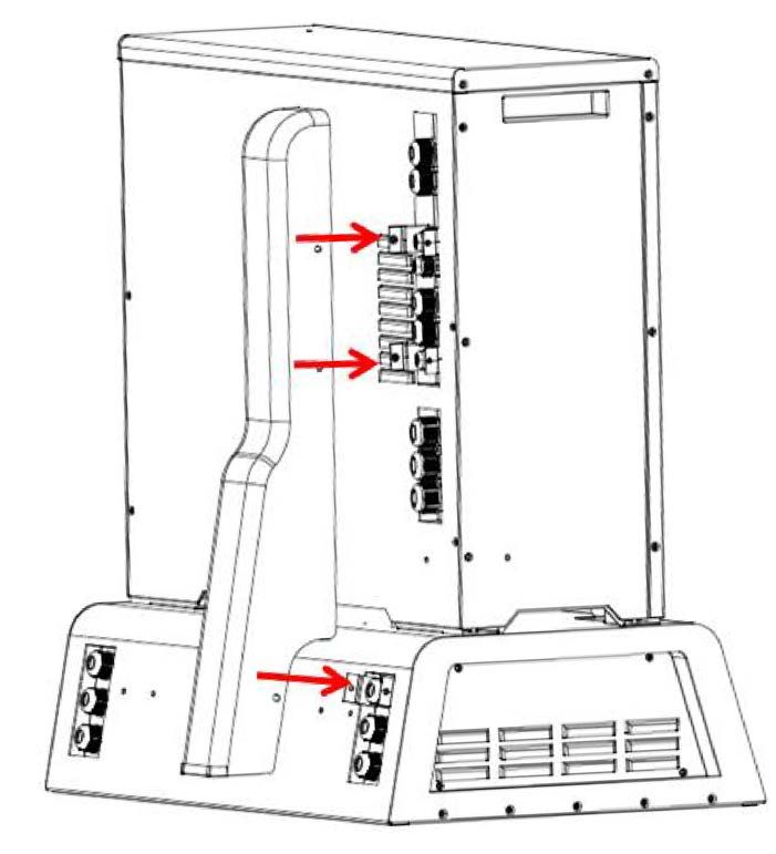
Close the breaker
After finishing all the connections, comprehensively check and ensure cables are well
connected. Then close the MINI ES 3kW/3kWh &MINI ES battery base breaker.
Shown as below:
31figure24. the position of circuit breaker on MINI ES battery base
NOTICE!
• Please ensure wago connectors are not under strain to avoid bad connection. A
comprehensive checking is required after completing the connection.
4.7. Trial operation of device
Check before trial operation
Please refer to chapter 4.3 in the MINI ES 3kW/3kWh installation manual check before
operation.
Supply power and start
CAUTION!
Before startup the System, the installer need to disconnect the circuit
breaker and carry out the following inspection:
• Double check and make sure the connection is correct according to the manual
instruction.
• Ensure that MINI ES3kW/3kWh and MINI ES battery is fixed tightly
DANGER!
Risk of short circuit
Incorrect wiring may cause short circuit.
Short circuit test shall be performed before system commissioning.
Only close the MINI ES circuit breaker on grid supply to system.
Press “Power” button for 10s, and start the system
Note: Long press "POWER" button for about 5seconds, "power" lamp ring light ( press the
32"power" button for about 10 seconds, "power" lamp ring turn off, system shutdown.)
It’s a normal phenomenon that during the start-up process that "power" for "local" "remote"
lamp ring will flicker at the same time when waiting for circle power lamp ring light.
After “POWER" lamp ring light, “POWER” indicator light flashes around 1-2 minutes, this
is a normal phenomenon that self-test process during the system start-up time. After self-
inspection ended, “POWER" and "LOCAL" indicator lights will keep lighting, then the
system is completed start-up.
Check “POWER” “LOCAL” indicator light;
Normal condition: “POWER”indicator light is always on, at the same time“LOCAL”
indicator light is always on. Display as follow.
REMOTE LOCAL POWER
figure25. Normal state
Fault state: "POWER" indicator light is flashing. (MINI Battery base and MINI ES
3kW/3kWh did not connect successfully)
"LOCAL" indicator light is flashing. (Not connect to grid or no electricity power from grid)
Record results are as follows:
Configure MINI ES 3kW/3kWh &MIINI ES battery base
CAUTION!
• work can be carried out only after the wiring of MINI ES 3kW/3kWh and MINI ES
battery base finished.
• Ensure that the circuit breaker of MINI ES 3kW/3kWh and MINI ES battery base
have been closed and the system start-up before configuration.
Note: More information can be viewed "MINIES monitoring software using manual"
After the completion of the MINIES external wiring work, start-up the MINIES, and use the
monitoring software provided by BYD to configure MINIES
figure26. Monitoring software icon
Double-click the icon to open the MINIES monitoring software.
33figure27. Monitoring software startup page
After the success of the software initialization into the 【main interface】, at the same
time serial port configuration window Popup:
figure28. Serial port configuration window
Confirm that the UT-850 converter has been connected to the computer and MINIES.
Choose UT-850 actual occupation port of COM, set up the station address (slave
34address) 4, baud rate 9600 b and other data default, click on "open serial port", then you
can open the serial communication.
If the communication parameters are not configured properly, or the converter is
connected with problem, the interface will pop up prompt box that the communication
timeout, please double check the communication parameter configuration or the
converter line connection.
figure29. Communication timeout prompt box
figure30. MINI ES monitoring software main interface
Click on the "users" - "login" in the menu bar,
35figure31. User login interface
Only after the user login that the configuration of MINI ES 3kW/3kWh &MINI ES battery
base can be proceeded.
Click on “Control” on the upper left corner of the select page, and choose the “Parameter
Config” in the drop-down menu.
figure32. Set the BECU number
figure33. Select “Parameters config”
Set the number of BECU to 2, keep other parameters to the factory default parameters.
36figure34. Set the BECU number to 2
After finish the configuration, need shutdown MINI ES, and disconnect the circuit
breakers of MINI ES 3kW/3kWh and MINI ES battery base. After completing the closing
action, once again closed the circuit breakers of MINI ES 3kW/3kWh and MINI ES battery
base, and restart the system. Then re-enter into the BECU configuration interface, if the
number of BECU display is 2, the configuration is successful. And check the “Group
Status” on the home page, if the status display b00000001, said that currently only MINI
ES 3kW/3kWh merged. If the status display b00000010 said that only MINI ES battery
base merged currently; if the status display b00000011 said MINI ES 3kW/3kWh and
MINI ES battery base has been successfully incorporated.
37figure35. Check the “Group Status”
Check running information of MINI ES 3kW/3kWh and MINI ES battery base.
Enter the “Debugging” interface, click on “Debug Advanced” at the bottom right corner,
set the number of PCS to 1, BECU number to 2 and click “Confirm”.
figure36. Set the PCS and BECU number
After completing the above configuration, enter the “info Device”, you can view the
running information of MINI ES 3kW/3kWh and MINI ES battery base.
38figure37. Check the MINI ES 3kW/3kWh running information
figure38. Check the MINI ES battery base running information
If there are special changes needed, please contact BYD authorized engineer or agent.
If the software used is not consistent with the software in the manual, please contact BYD
and ask for the latest version of the software.
Failure List
Register Register Defination Maintenance Methods
Address
3007 bit0:battery discharge is over current System automatic protect , clear
fault after stop
bit1:battery charge is over current System automatic protect , clear
fault after stop
bit2:battery low voltage Charge battery externally
bit3:battery severe high voltage Replace battery
39bit4:battery high voltage Wait battery self-discharge
bit5:battery severe low voltage Replace battery
bit6:disconnection of sampling line Check sampling line and replace it
bit7:discharge when low voltage System automatic protect , clear
fault after stop
bit8:voltage sample line abnormal Check sampling line and replace it
bit9:current sample abnormal Check sampling line and replace it
bit10:battery abnormal Check sampling line and replace it
bit11:precharge depression Check prefilled resistance and
replace it
2011 bit0:control current overload 100%
bit1:control current overload 110%
bit2:control current overload 150%
bit3:control current overload 200%
bit4:control current overload 220%
bit5:control current overload 300%
bit6:transient current overload 300%
bit7:grid current overload
bit8:locking wave error
bit9:drift error
bit10:grid voltage drift error
bit11:control current drift error
bit12:contravariant current drift error
bit13: grid current drift error
bit14:PDP protect
bit15:hardware protect
4.8 Reassemble the MINI ES
Before reassemble the MINI ES, please make sure the grid supply has been disconnected
by the circuit breaker, turn off the system and had CT removed. Running again after
cleaned up the site, then reclose CT.
Install left and right side covers of MINI ES 3kW/3kWh and battery
base
DANGER!
• Before installing sideboard, please make sure the energy storage system has
already been turned off and deenergised.
Before install the left side panel, connect the grounding cable which is on the bottom
of the left side cover, shown as below:
40figure39. Install grounding cable at left side
When installing left side cover, firstly move to the right and then move upward, make
sure the holes are aligned, then can fasten side cover.
figure40. Install left side board
Then tighten six screws(related tool: Phillips head screwdriver)
41figure41. Install left side board
Before install the right side panel, connect the grounding cable which is on the
bottom of the left side cover, shown as below:
figure42. Install grounding cable at right side
When installing right side cover, firstly move left and then move upward make sure
the holes are aligned, then can fasten side cover.
42figure43. Install right side board
Then tighten six screws(related tool: Phillips head screwdriver)
figure44. Install right side board
43figure45. Install left side board of battery base
figure46. Install right side board of battery base
Fixing the cable protective cover of electrical connection hole
The cable protective cover of MINI ES 3kW/3kWh and the battery base in the following
figure must be fixed tightly (related tools: spanner).
44WARNING!
In order to prevent water and small insect from entering the internal system, what’s
more ,to prevent the internal cables of the system from bearing too much tension,
the cable protective cover of electrical connection hole cover must be fixed firmly.
figure47. Fixing the cable protective cover
figure48. Diagram of electric connection holes’ location
45figure49. Install the cable protective cover
figure50. Fixing the frame of the cable protective cover
46figure51. The effect picture after installation is completed
Clean up the site.
Clean out rubbish and packing on site
Clean up the room and clean out the rubbish generated during installation.
Start operation
Close all related circuit breakers, the system will be switched on, then the system will
automatically run; and then inform the customer that installation is complete.
Daily maintenance
1. Do not block the product inlet / outlet. The inlet and outlets should be cleaned every six
(6) months.
2. When the product is likely to sit idle, please ensure that the product has sufficient battery
power. (Via long press "LOCAL" and "REMOTE" 2 buttons for charging the battery. Once
fully charged, the product will automatically shut down. Then turn off the power grid
connecting to the MINI ES).
47NOTICE!
Beyond the prescribed time limit or not in accordance with the requirements
of operation, may cause the risk of battery over-discharge. This kind of
damage to battery is beyond the scope of warranty.
• When the product is likely to sit idle, please operate in accordance with the
content step2 in "Daily maintenance" . Once fully charged, placement time shall
not exceed 6months
• As system do not access to the grid resulting in automatic shutdown, product
placement time shall not exceed 1 months.
4.9 Attached list
Tool list
No. Tool name Tool type Functions
1 Stanley knife
2 Phillips head screwdriver
3 Flat-bladed screwdriver
4 Small flat-bladed screwdriver CT terminal
5 Spanner M14 Fix anchor bolts
6 Electric drill and drill bit NO.10 drill Punch anchor bolts
7 Hammer
8 Long-nose pliers
9 Wire strippers
10 Wire crimpers
11 Crimping modular plier
12 Multi-meter
13 Adjustable wrench
14 Scissors
15 Tape
Other auxiliary tools that might
be used (for example: All installation
16
Insulating gloves, insulating process
shoes, insulating tape, etc.)
485. Daily Maintenance Methods
5.1 Common faults
Common faults Operation methods
MINI ES can’t start Please check the battery circuit breaker closed or not
(licensed technician required).
MINI ES has no power Please check batteries state of charge via APP, it might be
output too low.
Essential load can’t work 1. Please check the important load distribution box circuit
normally breaker.
2. Please check the essential load rating to determine if it
exceeds 2kVA or not.
3. Please check the state of charge.
APP can’t read data Please check the product network connections.
The MINI ES sends power Please contact your service agent.
to the grid
Others If the product is unable to recover, please contact the
supplier or local service centre.
5.2 Daily maintenance
1. Do not block the product inlet / outlet. The inlet and outlets should be cleaned every six
(6) months.
2. When the product is likely to sit idle, please ensure that the product has sufficient battery
power. (Via long press "LOCAL" and "REMOTE" 2 buttons for charging the battery. Once
fully charged, the product will automatically shut down. Then turn off the power grid
connecting to the MINI ES).
NOTICE!
Beyond the prescribed time limit or not in accordance with the requirements
of operation, may cause the risk of battery over-discharge. This kind of
damage to battery is beyond the scope of warranty.
• When the product is likely to sit idle, please operate in accordance with the
content step2 in "Daily maintenance" . Once fully charged, placement time shall
not exceed 6months
• As system do not access to the grid resulting in automatic shutdown, product
placement time shall not exceed 1 months.
496. About BYD
For any assistance about BYD product, please contact BYD by:
Electric Power Research Institute
BYD Auto Industry Company Limited
NO.3009, BYD Road, Pingshan, Shenzhen, 518118, P.R.China
Tel:+86 0755-89888888 – 64186
50You can also read