INVESTIGATION OF A MACHINE-PLANT INTERFACE FOR EXTRACTING ROOTED INVASIVE AQUATIC PLANTS
←
→
Page content transcription
If your browser does not render page correctly, please read the page content below
Michigan Technological University
                                                      Digital Commons @ Michigan Tech

Dissertations, Master's Theses and Master's Reports

2021

INVESTIGATION OF A MACHINE-PLANT INTERFACE FOR
EXTRACTING ROOTED INVASIVE AQUATIC PLANTS
Brad Baas
Michigan Technological University, bdbaas@mtu.edu

Copyright 2021 Brad Baas

Recommended Citation
Baas, Brad, "INVESTIGATION OF A MACHINE-PLANT INTERFACE FOR EXTRACTING ROOTED INVASIVE
AQUATIC PLANTS", Open Access Master's Report, Michigan Technological University, 2021.
https://doi.org/10.37099/mtu.dc.etdr/1202

Follow this and additional works at: https://digitalcommons.mtu.edu/etdr
   Part of the Applied Mechanics Commons, and the Natural Resources and Conservation Commons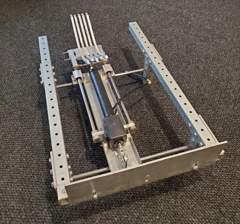
INVESTIGATION OF A MACHINE-PLANT
INTERFACE FOR EXTRACTING ROOTED
    INVASIVE AQUATIC PLANTS
                                 By

                            Bradley Baas

                            A REPORT

Submitted in partial fulfillment of the requirements for the degree of

                      MASTER OF SCIENCE
                     In Mechanical Engineering

         MICHIGAN TECHNOLOGICAL UNIVERSITY

                                2021

                        © 2021 Bradley Baas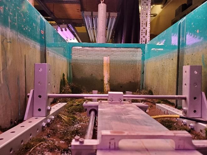
This report has been approved in partial fulfillment of the requirements for the
Degree of MASTER OF SCIENCE in Mechanical Engineering.

                   Department of Mechanical Engineering-Engineering Mechanics

          Report Co-Advisor:       Dr. Paul van Susante

          Report Co-Advisor:       Dr. Guy Meadows

         Committee Member:         Dr. Andrew Barnard

           Department Chair:       Dr. William W. Predebon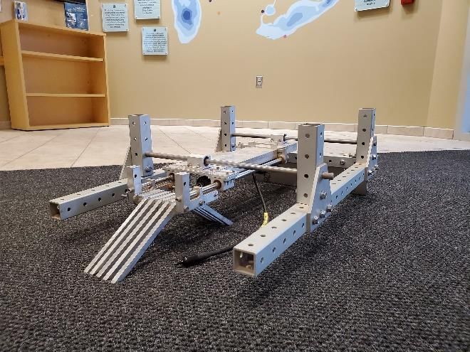
iii
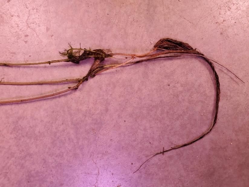
Table of Contents
Acknowledgements….…………………………………………………………………... v

Abstract………….……………………………………………………………………… vi

1   Introduction……………………………………………………………………..….. 1

2   Background………………………………………………………………………….. 1
     2.1 Eurasian Watermilfoil Impacts and Management…………………………….. 1
     2.2 The Invasive Aquatic Plant Extractor………………………………………… 2
3   Materials and Methods…………………………………………………………….. 3
     3.1 Test Fixture…………..……………………………………………………….. 3
     3.2 Test Tank Preparation…………………..……………………..……………… 5
     3.3 Tine Design…………...………………………………………………………. 6
     3.4 Turbidity Measurements………..…………………………………………...... 7
     3.5 Force Measurements…….………………………………….……………….... 8
     3.6 Plant Removal Assessment..…………………………………………………...9
     3.7 Tine Configurations and Geometries….…………………………………..… 12
4 Results……………………………………...……………………………………….. 14
     4.1 Pattern of Substrate Buildup Around Tines……………………...…………... 14
     4.2 Tine Configuration and Geometry Comparison……………………………... 15
5   Discussion…………………………………………………………………………... 18
     5.1 Further Test Insights………………………………………………………… 18
     5.2 Future Work………………………………………………………………… 19
6   Conclusion……………………………………………………………………...…... 20

7   Works Cited………………...……………………………………………………… 21

                                  iv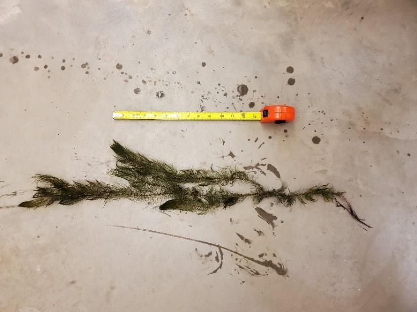
Acknowledgements
I would like to thank the individuals who lent their time and expertise to this research
project. I would not have been able to complete it without them. My advisors, Dr. Paul
van Susante and Dr. Guy Meadows helped me lay the groundwork for my test and
measurement plans. Dr. Paul van Susante, Dr. Guy Meadows, and Dr. Andrew Barnard
gave me timely feedback on this report to improve its clarity and accuracy. Professor
Casey Huckins was instrumental in helping me set up the lab with equipment and advice
for growing aquatic plants. Jon Lund, Marti Toth and Mark Somero gave me useful
manufacturing guidance and ideas. Chris Pinnow, Jamey Anderson, Jacob Lundin, and
Professor Corey McDonald contributed to test equipment setup. Jason Swain and Aiden
Truettner helped me find substrate and move it into the lab. Somer Schrock helped me
collect test plants and edited drafts of this report. I would also like to thank Dr. Dave
Roseman, along with Dr. Guy Meadows, for jumpstarting this project in 2019 and for
their continued interest in seeing this work move forward.

                                            v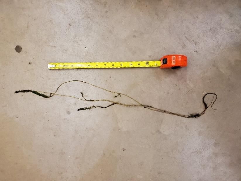
Abstract
        The current solutions for managing rooted aquatic invasive plants are time
consuming, have negative environmental impacts, or are cost-limiting for management
organizations. The most effective treatment method is hand pulling, but hand pulling is
not a feasible solution for a whole lake. A new device, the invasive aquatic plant
extractor, aims to replace human divers who hand pull plants with a mechanical system.
The device implements a machine-plant interface that resembles the tines of a fork. These
tines will be pushed linearly through the substrate, and then raised from the substrate with
the plant caught in the tines. The primary purpose of this paper is to discuss the impacts
of tine configuration and tine geometric traits on tine performance and identify tine
geometry that consistently removes the target plants. Force, turbidity, and plant removal
capability data were collected. All testing occurred in tanks containing representative
substrate and common, rooted invasive plants. Wide tines with wide spacing perform the
best of the four configurations tested. Tines with square or rounded edge shape perform
better than pointed edges. Increasing the tine rake angle with respect to a vertical plane
increases the performance of the tines. The data collected in this study suggests that tines
will be part of an effective invasive aquatic plant extractor.

                                             vi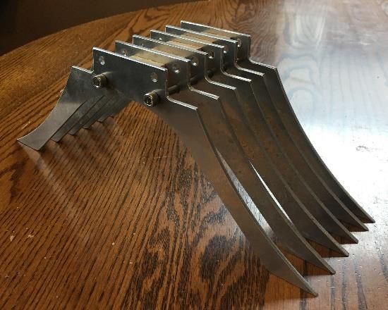
1 Introduction
        Aquatic invasive species (AIS) are prevalent throughout North American [1] and
European [2] waterbodies. AIS impede access to, decrease biodiversity in, and decrease
property values on the waterbodies they inhabit. Current management methods for AIS
are time consuming, cost prohibitive, and adversely impact native plants and animals.
Fibrously rooted invasive plants are widespread and commonly problematic [3]. Hand-
pulling fibrously rooted plants is the least environmentally harmful method of removal;
however, it is time consuming and expensive. In 2019, a machine to “hand-pull” plants
was proposed by the author of this report. The
final vision for the machine is a system that can
identify, move to, and remove a target plant with
minimal human input. The preliminary machine
design was completed in 2020 by Michigan
Technological University Senior Capstone Design
Team 11. Team 11’s end effector for removing
aquatic plants with fibrous roots, seen in Figure 1,
required further research to meet the
environmental requirements of the State of
Michigan for aquatic vegetation removal. To learn Figure 1. More research will be performed on
more about how an end effector will interact with      the configuration and geometries of an end
plants with fibrous roots and the surrounding          effector similar to the Senior Capstone Design
                                                       Team 11 end effector, seen here.
substrate, potential configurations and geometries
of a comb-like machine-plant interface were studied by the author of this report.

The specific objectives of the research are:
 • Identifying end-effector spacing, width, edge shape, and rake angle that consistently
   achieve complete plant removal.
 • Limiting sediment kickback while working in the substrate to maintain underwater
   visibility to increase the effectiveness of a future, automated plant identification tool.
 • Reducing forces required for plant removal to reduce mechanical design challenges.

2 Background
2.1 Eurasian Watermilfoil Impacts and Management
        The most widespread and aggressive fibrously rooted non-native aquatic plant in
the United States is Eurasian Watermilfoil (EWM). EWM is present in over 45 U.S.
states and 3 Canadian Provinces [3]. Depending on the trophic state and sediment type,
EWM can colonize an entire lake [4]. EWM can form thick, tangled surface mats that
shade out native plants. Thick EWM growths clogs boat propellers, making boating and
recreation difficult or impossible [5].

                                                  1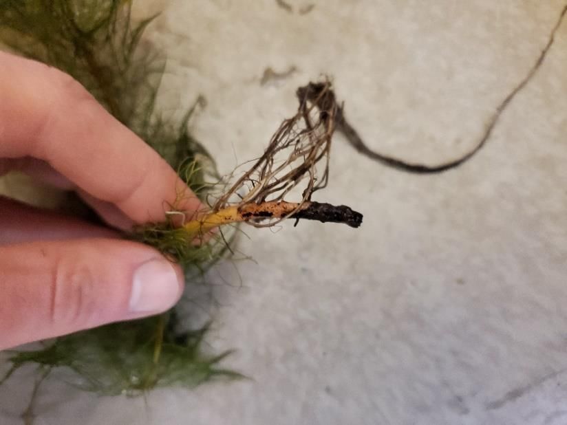
Cutting, herbicide, benthic barriers, and Diver-Assisted Suction Harvesting
(DASH), are the primary methods of EWM population management. There are several
drawbacks to these methods. Cutting is not an effective method because EWM
reproduces primarily by fragmentation. Cutting serves to spread the plant [2]. Herbicide
is not species-selective, and it kills native plants that are biologically similar to EWM [6].
Herbicide applications can create dead zones that negatively impact the ecosystem [6].
Additionally, herbicide applications to waterbodies used as drinking water supplies have
raised human health concerns [7]. Benthic barriers can be difficult to anchor, and they
require regular inspections [8]. Benthic barriers negatively impact aquatic habitats. A
study of benthic barriers in Texas and Wisconsin waterbodies found that invertebrate
population density beneath benthic barriers was 10-31% of populations not underneath
benthic barriers [9]. Benthic barriers must be applied to an area for 8 weeks to effectively
manage EWM [10]. DASH is a more efficient way of hand-pulling plants; however,
DASH is still very labor and time intensive. Between 2013 and 2015, DASH divers on
Squam Lakes in New Hampshire averaged 5.1 gallons of EWM removed per hour. As
another point of reference, DASH divers at Pentwater Lake in Michigan worked for four
days to remove 15,200 pounds of biomass at a total cost of $21,533, or about $1.42 per
pound of biomass [11]. The divers at Pentwater Lake worked in an area about 12,000
square feet of a lake with a surface area of 431 acres (1.88 e+7 square feet) [11].
Management methods that are this expensive may prohibit lake organizations from
effectively managing EWM.
2.2 The Invasive Aquatic Plant Extractor
         During the 2019-2020 academic year, Michigan Technological University Senior
Capstone Design Team 11 developed a mechanical system to remove invasive plants.
The aim of this machine is to replace divers who hand-pull
invasive plants. Figure 2. is a CAD model of the prototype
of the invasive aquatic plant extractor. The invasive aquatic
plant extractor will be affixed to the outside edge of a boat
[12]. The central post is lowered from the boat into the
substrate. A winch-driven collar translates vertically along
the post and presses the tines into the substrate while the
parallelogram linkage, which is one meter in length, is held
stationary.
         The linear actuator and parallelogram linkage then
move the tines through the substrate towards or away from
the central post. The tines catch the root crown of the target
plant, lift the plant from the substrate, and a hose with light
suction transports the plant to the surface, completing a
successful removal. At the conclusion of the project, the       Figure 2. Invasive Aquatic Plant
                                                                  Extractor Concept. Reproduced From
                                                                  [12]
                                               2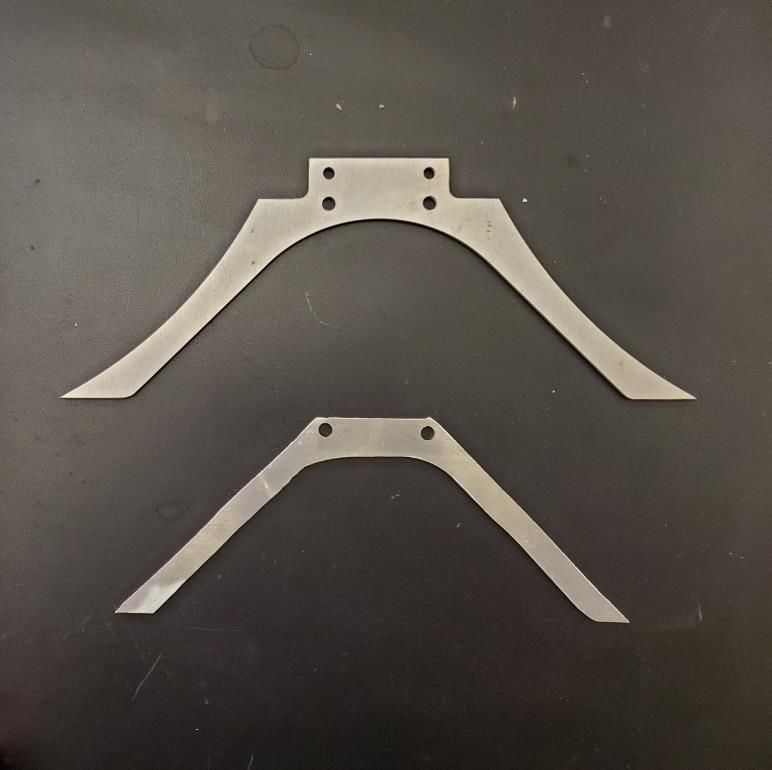
tines had been briefly tested, but the final design had yet to be verified [12].
The invasive aquatic plant extractor will have a system to guide it to target plants.
Reduced water clarity may limit application of this system. The impact of the tines on
water clarity had not been determined.
Team 11’s work was the basis for a set of requirements that are addressed by this
study, shown in Table 1. The research presented here increases knowledge pertaining to
the details of these objectives.
Table 1. Engineering Objectives developed from Team 11 Research
Objective Requirement Details
Less than 5% of plants are broken including
Broken Plant Rate and above the root crown during removal
from sediment
Tines must reach no less then 100mm into
Tine Depth
substrate
Total tine block width must not exceed
Tine block width
100mm
Pushing the tines through the substrate must
Maximum System Load
require less than 400N of force
Disturbed Sediment Volume Substrate volume disturbed must not exceed
per plant removed 1500 cm3 per plant removed
3 Materials and Methods
3.1 Test Fixture
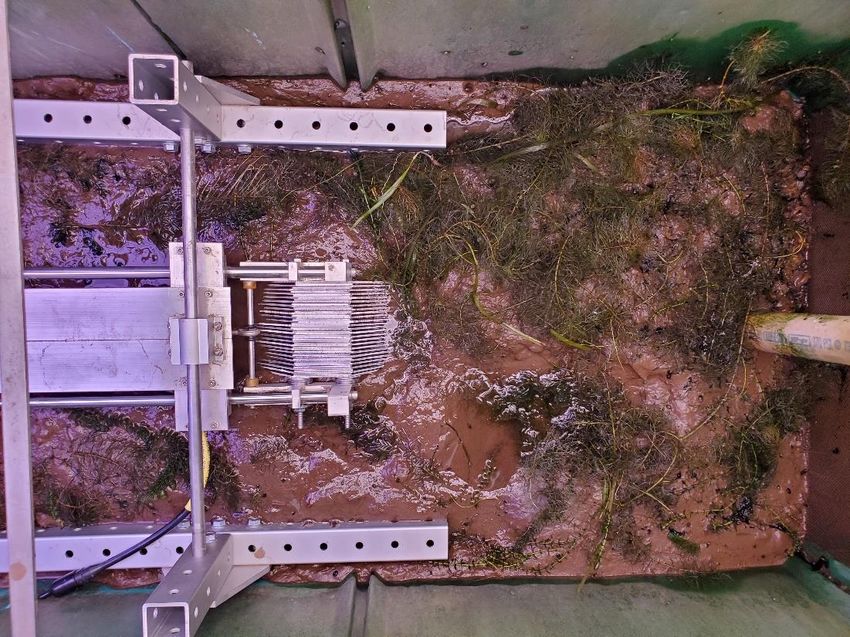
As seen in Figure 3, a test fixture was designed to push the tines through the
substrate along the x-axis and allow the tines to be repositioned along the y-axis. Tine
configurations up to 100mm in width can be accommodated by the fixture. The invasive
aquatic plant extractor is intended to dislodge plants by pushing the tines through the
substrate. For this study, the tines were inserted 75mm into the substrate and then pushed
150mm through the substrate by a linear actuator. The tines remained in the substrate
through the 150mm motion. 150mm was an appropriate actuation distance for loosening
plants during preliminary trials. The speed of the tines was 0.75 inches/second. Force and
turbidity data were collected while the tines were moving. After the tines stopped
moving, the target plant underwent a removal quality analysis to check for fragmentation,
missed plants, loose plants, and other factors that could affect removal.
3Turbidity Measurement
Region
Tine Path Range
150 mm
Tine Path 100 mm
y
x
Figure 3. An overhead view of the tines and test fixture in a drained tank. The tines were pushed
through the substrate 150mm along the tine path. They can be repositioned so that multiple
tine paths are possible for each test stand position.
The bottom of the test
fixture is shown in Figure 4. Tines Linear
The fin was pushed 75-100mm Bearing
into the substrate to keep the
test fixture stationary while the
tines moved. Its surface area is
much larger than the tines, and
the test fixture did not move
during testing. Stationary linear
bearings and shaft guides, fixed Shaft
to the end of the linear shafts, Guide
guided the tines along a linear
path. The tines, and electric
linear actuator are also seen in
this figure.
Fin
Figure 4. Flipping the test fixture upside-down reveals its important
components. The linear actuator and linear guide system work together to
move the tines forward through the substrate. The fin, closest in frame,
was pushed into the substrate to keep the fixture stationary.
4As seen in Figure 5, the frame of the test fixture rested on the substrate, and the
tines and fin protruded below the test fixture frame.
Figure 5. The tines and fin protruded below the test fixture frame (l), and the test fixture frame sat on top of the substrate
(r)
3.2 Test Tank Preparation
Three Living Stream LS-900 tanks were prepared with 100mm of substrate and
representative plants five months prior to testing. Tank 1 contained muck substrate and
Myriophyllum Heterophyllum. Tank 2 contained a muck/sand mixed substrate and M.
Heterophyllum. Tank 3 contained muck and Myriophyllum Spicatum (EWM).
The bulk density of the muck was 36% less than the bulk density of the
muck/sand mix. The plants received nine hours of full-spectrum lighting each 24-hour
period. Twice per month, algae were manually removed from the plants, half of the tank
water was replaced, and the plants were agitated. These treatments attempted to simulate
a natural ecosystem with waterflow and wave action. The water in the tanks was from the
Keweenaw Waterway. Muck was collected from Chassell Bay, part of the Keweenaw
Waterway. Sand was collected from the Pike River in Chassell Township. Figure 6.
includes pictures of the tank substrates. M. Heterophyllum was purchased through an
aquarium supply company, and M. Spicatum fragments were gathered from the
Keweenaw Waterway. As shown in Figure 7, The plants were typically spaced 120 –
150mm apart after five months of growth. The water depth during growth was between
280mm and 320mm.
5Figure 6. Muck (l) and muck/sand mix (r) substrate types were used for testing. The
bulk density of muck was 36% less than the bulk density of the muck/sand mix.
Plants Water
280-320mm
120-150mm
75mm
Substrate 100mm
Figure 7. Tank cross section showing the depth of the tines, substrate, plant spacing, and water depth for testing.
The substrate depth in the tanks was 100mm, the plants were spaced 120-150mm apart after five months of growth,
and the water depth was 280-320mm.
3.3 Tine Design
The tine design considered the intended operation of the invasive aquatic plant
extractor designed by Senior Design Team 11 and the observed dimensions of the target
plants. The invasive aquatic plant extractor was designed to remove plants in two
opposing directions, and the tines for this study were designed accordingly. Figure 8
compares the tines that were manufactured for this study to the tines manufactured for
Senior Design Team 11. Both tines had 45° rake angles. As can be seen in the figure, the
distance from the mounting point to the tip of the tines for this study was 95mm, 18mm
less than the tines manufactured for Team 11. Team 11’s tines were longer because they
were designed to reach under the entire root system of the target plants, however, it is
6now known that just the root crown needs to be extracted to successfully remove a plant.
Root crowns of the two plants discussed in this study can regrow into full plants if they
are left in the substrate. Pre-test observations of M. Heterophyllum found the deepest root
crowns to be 60 mm below the substrate. The tines for this study were designed to reach
75mm into the substrate to capture the deepest root crowns. The tines for this study had
straight leading edge to standardize rake angle tests. A consistently influential curved
profile would have been difficult to maintain for rake-angle testing. The distance from
the center of the tine to the top of the leading edge was shortened from 50mm to 30mm
because the tine mounting method was simplified for the test fixture.
Team 11 tine 165mm
50mm
Leading
Edge
45°
113mm
Mounting
Point
Leading
Edge
45°
95mm 30mm
130mm
Study tine
Figure 8. The height at leading edge shape of the tines used for this study (bottom) differed in from the tines
manufactured for Senior Capstone Design Team 11 (top). The tines used for the study were shorter because of
greater understanding of the target plant, and the leading edge shape was simplified for consistent rake angle
testing.
3.4 Turbidity Measurements
The invasive aquatic plant extractor will require a plant identification tool that
may only be able to identify plants in clear water. Turbidity is a measure of the amount of
light that is scattered by material in the water when light is shined through a water sample
[13]. Turbidity was used to track changes in clarity caused by tine movement, and it was
measured by an In-Situ Aquatroll 600. Five minutes of turbidity measurements were
taken for each trial, and measurements started 10-15 seconds before the tines started to
move. Turbidity measurement frequency was 1 Hz, and the units were nephelometric
turbidity units (NTU). Water volume was kept constant for all trials and between tanks to
ensure turbidity was comparable between tests. Preliminary testing showed that the
7maximum turbidity increase outside of the tine path occurred around the end of the tine
path, as show in Figure 4. Testing showed that the upper limit for clear, underwater
imaging lies around 8 NTU, as demonstrated by Figure 9.
Figure 9. M. Spicatum in 4 NTU water (l) and 12 NTU water (r). The camera was one foot away from the plants. It
is impossible to distinguish between plant species in the 12 NTU image. Clear underwater images can be taken in
water up to around 8 NTU.
3.5 Force Measurements
The amount of force required for plant extraction will impact the design of the
invasive aquatic plant extractor. Stronger mechanical and electrical components would be
required to overcome higher forces. Cost would most likely increase with higher forces,
as well. Force was calculated from the power required by the actuator. The data
acquisition system was calibrated with seven weights applied to the actuator. Two, third-
order voltage-force relationships were noted during testing. It is not understood why there
were two relationships, however, the force measurements taken with both relationships
appear to be consistent. Figures 10 and 11 show these two relationships. These two
relationships do not overlap for the forces seen in this study. The first relationship applied
to tests 1-4 and 7-8. The second relationship applied to tests 5 and 6. The calibration
voltage ranges, relationship coefficients and R2 values are shown in Table 2.
400 400
Actuator Force (N)
Actuator Force (N)
350 350
300 300
250 250
200 200
150 150
100 100
50 50
0 0
0 0.02 0.04 0.06 0.0000 0.0100 0.0200 0.0300
Shunt Voltage Drop (V) Shunt Voltage Drop (V)
Figure 10. The first relationship between the force Figure 11. The second relationship between the
produced by the actuator and the voltage drop force produced by the actuator and the voltage
across a shunt applied to tests 1-4 and 7-8. drop across a shunt applied to tests 5 and 6.
8Table 2. Parameters of Two Force-Voltage Relationships
Best Fit Equation: y = ax3+bx2+cx+d (y symbolizes force in newtons, x
symbolizes voltage across the shunt)
Parameter Relationship 1 Relationship 2
Calibration Range
0.0289 - 0.0431 0.0095 - 0.0229
(shunt voltage)
R2 0.999 0.9996
a 70157015.91 48472707.99
b -8415881.896 -2699196.376
c 353481.3257 72807.3955
d -4881.025763 -491.2074755
3.6 Plant Removal Assessment
Plant removal capability was assessed qualitatively. The substrate region impacted by the
tines was inspected before and after the tines were retracted. Trials in clear water were
filmed and photographed to aid judgement of how the tines were interacting with the
substrate and plants. Root position and soil position around the tines was inspected and
measured, respectively. Measurements x, y, and z, as indicated in Figure 12, were taken
for each trial. The number of loose plants, the number of fragment zones, and the number
of plants in the tine path, but not removed (“missed”), were recorded. Plants that were not
firmly anchored were removed by pulling on the stem. They were then photographed.
The invasive aquatic plant extractor will separate the plants from the substrate with
suction, so pulling by the stem was a relatively representative method of removal. Figures
13 through 18 show the difference between a complete plant and a fragmented zone for
both species.
9Plant
Water
x
y z
Rake
Angle
Substrate Tine Direction
Figure 12. Typical substrate buildup around the tines after a trial. Three measurements, indicated by x, y, and z were
taken for each trial. Plant looseness and root position relative to the tines were also inspected.
Figure 13. Complete M. Spicatum Plant with 30cm Figure 14. Complete M. Heterophyllum Plant with
ruler for scale 30cm ruler for scale
10Figure 15. Complete M. Spicatum Root Crown Figure 16. Complete M. Heterophyllum Root Crown
Figure 17. Fragmented M. Spicatum Stem. Each Figure 18. Fragmented M. Heterophyllum Stem.
removed plant was inspected for fragmented Each removed plant was inspected for
zones. fragmented zones.
113.7 Tine Configurations and Geometries
Tine width, tine spacing, edge shape, and rake angle were the configuration and
geometry parameters tested. Eight tests of five trials each tested how these parameters
impacted removal force, turbidity, and plant removal capabilities.
Tests 1-4, detailed in Table 3, tested edge width and tine spacing. The number of
tines for each configuration was the maximum that could fit in the 100mm space. Figures
19 and 20 show the four tine configurations, which are made up of 2.03mm- and
9.53mm-wide tines and spacers. 9.53mm is approximately 4.5 times 2.03mm, which was
assumed to be a large enough width difference for there to be differences in configuration
performance.
Table 3. Tine Configuration Tests
Test Tine Width (mm) Tine Spacing (mm) Number of Tines
1 2.03 9.53 9
2 2.03 2.03 25
3 9.53 9.53 5
4 9.53 2.03 8
Figure 19. From left to right, nine 2.03mm tines with 9.53mm spacing, 25 2.03mm tines with 2.03mm spacing, five
9.53mm tines with 9.53mm spacing, and 9.53mm tines with 2.03mm spacing. Although the picture here contains
just seven tines, the 9.53mm tines/2.03mm spacing configuration was tested with eight tines.
Figure 20. 9 2.03mm tines with 9.53mm isometric
view.
12Tests 5 and 6 tested the effect of leading edge shape on force, turbidity, and plant
removal success. Rounded edges and 40° points were milled into the highest-scoring tine
configuration from tests 1-4. The edge shapes are illustrated in Figure 21. Rake angle was
45° for tests 1-6. Tests 7 and 8 tested 56° and 27° rake angles, respectively. The three
rake angles tested are pictured in Figure 22. Rake angle is defined in Figure 22. The edge
shape for tests 7-8 was square. Details of tests 5-7 can be seen in Table 4.
Table 4. Edge Shape and Rake Angle Tests
Test Leading Edge Shape Rake Angle
5 Round 45°
6 Pointed 45°
7 Flat 56°
8 Flat 27°
α
40°
Figure 21. Round and point edge shapes were milled into the Figure 22. The three rake angles
tines for tests 5 and 6, respectively. The picture on the right is indicated by α (from top to bottom)
tines with a point edge shape. Edge shapes were only applied are 56°, 45°, and 27°. Tests 1-6 used a
to the leading edge of the forward direction, noted in Figure 45° rake angle. The 56° rake angle was
20, of the tine. tested in test 7, and the 27° rake angle
was tested in test 8.
134 Results
4.1 Pattern of Substrate Buildup Around Tines
Figures 12 and 23 – 25 illustrate the typical substrate buildup around the tines
after a trial. The tines pushed the substrate forward, raising a portion of substrate in front
of the tines, denoted by measurement x in Figure 12, and leaving a trough behind the
tines, denoted by measurement z in Figure 12. The plants in the path would move with
the tines if they were loosened and contacted by the tines. There was a space beneath the
tines which was void of substrate in about 25% of trials, denoted by measurement y in
Figure 12.
Tine Direction
Raised Substrate Tines Trough
Figure 23. Top view of the region impacted by tines. The tines create an area of raised substrate and a trough as
they move forward.
Figure 24. Substrate pile in front of tines after a Figure 25. Substrate trough behind tines after a
trial. Trials had been performed along the width of trial
the tank prior to the taking of this picture. The
substrate mound is wider in this figure than in
Figure 23.
144.2 Tine Configuration and Geometry Comparison
Tables 6 through 8 report surface area, average force, turbidity change, and
potential plant removal success. Surface area, as shown in the table, is the actual surface
area of the leading face of the tine block. Average force was calculated from all
measurements taken while the tines were moving. Turbidity change, as reported in tables
6-8, is the difference between the turbidity prior to the tines moving, and 30-40 seconds
after the tines stopped moving. Plant removal potential is a rating given based on the
interaction of the tines with the plants and substrate where a “one” is a low rating. The
criteria of the rating system are described in Table 5. The rating system was formed
relative to the other tests in the study, and it accounts for missed plants, fragmented
plants, and other issues that impede successful plant removal.
Table 5. Plant Removal Potential Rating System Criteria
Plant Removal
Criteria
Potential
5 No issues noted
1. Seldom fragments or misses plants or
4
2. Some plants in tine affected area are not loose after tine motion
1. Regularly fragments or misses plants or
3
2. Some plants in tine affected area are not loose after tine motion
1. Regularly misses or fragments plants and
2
2. Substrate not loose in tine affected area
1. Regularly misses or fragments plants and
1 2. clear potential to fragment plants during other motions in
removal process
The tine configuration tests are summarized in Table 6. The force data from these
tests shows a positive trend between tine surface area and force. The configuration of
9.53mm tines and 2.03mm spaces deviates from this trend, but this set of tines was tested
in a tank growing only M. Spicatum, which had much smaller root systems. Turbidity
generally increased with increased surface area. Turbidity decreased during three tests,
indicating the water was clearer after the trials than before the trials. The configuration of
9.53mm tines and 2.03mm spaces caused an increase in turbidity. The configuration of
2.03mm tines with 9.53mm spaces, test 1, missed plants. Plants remained rooted in the
substrate underneath and behind the tine block. The configuration of 9.53mm tines and
2.03mm spaces, test 4, had high fragmentation potential. As pictured in Figure 26, M.
Spicatum stems were stuck in between tines which did not allow the plants to be
removed. The configuration of 2.03mm tines and 2.03mm spaces, test 2, was tested in a
tank with M. Heterophyllum, which has thicker stems than M. Spicatum. It is predicted
that this configuration, with the same spacing as test 4, would catch plants in between the
tines. Plant removal potential for the 9.53mm tines, 9.53mm in spaces configuration was
15the highest among these configurations because it was the best at loosening the substrate.
It did so without missing or fragmenting more plants than test 1, and no plants were
caught in between the tines, as they were for test 4, and could have been for test 2.
Table 6. Tine Configuration Tests
Average Plant
Surface Fragmented
Average Turbidity Removal
Test Configuration Area and Missed
Force (N) Change Potential
(cm2) Plants (#)
(NTU) (1-5)
2.03mm tines,
1 13.7 75.2 -0.816 5 2
9.53mm spaces
2.03mm tines,
2 38.1 91.2 -0.317 1 2
2.03mm spaces
9.53mm tines,
3 35.7 81.4 -0.546 4 3
9.53mm spaces
9.53mm tines,
4 57.2 69.8 0.319 4 1
2.03mm spaces
Tine Direction
Stem in tension
Figure 26. Plants stuck in 0.08 in-space tines after a trial. These plants
started beneath the tines, however, plants in front of the tines were similarly
stuck in between the tines. Plants stuck in between tines were at high risk for
fragmentation.
16The edge shape tests, summarized in Table 7, were performed with the 9.53mm tine,
9.53mm space configuration. Pointed tines required less force than rounded tines to move
through the substrate. Turbidity decreased more during the pointed tine trials than the
rounded tine trials. Rounded tines and pointed tines allowed plants to slip through, and
the plants were frequently fragmented. A pointed tine trial clearly sliced a plant, leaving
the root crown in the substrate. Fragmented and missed plants were found in the tine path
after trials of both edge shapes.
Table 7. Edge shape tests were performed with a 9.53mm tine width, 9.53mm
tine space configuration and a 45° rake angle
Average Fragmented Plant
Edge Average Turbidity and Missed Removal
Test
Shape Force (N) Change Plants (#) Potential
(NTU) (1-5)
5 Rounded 79.2 -0.640 4 2
5 Point 61.8 -.992 2 2
Table 8 summarizes testing of rake angle. Test 3 is included in the table for
comparison. There is no clear trend in average force. All three rake angles were tested in
tanks containing M. Spicatum and M. Heterophyllum. Lower rake angles are correlated
with greater turbidity decreases. The 27° and 45° rake angles were similarly successful at
removing plants. The 27° rake angle did not consistently loosen its target plants, but it did
not fragment plants as frequently as the 45° rake angle. The 56° rake angle was the best
of this study. Every targeted plant was loose after the 56° rake angle tines contacted the
plant.
Table 8. Rake Angle Tests were performed with a 9.53mm tine width, 9.53mm
tine space configuration and a flat edge shape
Average Plant
Rake Angle Fragmented
Average Turbidity Removal
Test (relative to and Missed
Force (N) Change Potential
vertical plane) Plants (#)
(NTU) (1-5)
7 56° 97.0 -.266 0 5
3 45° 81.4 -0.546 5 3
8 27° 91.6 -1.26 1 3
175 Discussion
5.1 Further Test Insights
The results of this study suggest that 9.53mm tines with 9.53mm spaces at a rake
angle greater than 45° are the most effective at removing rooted invasive aquatic plants.
Edge shape should be flat. Rounded and pointed edges did not effectively remove plants.
The effects of tine spacing are demonstrated in the results of trials 1-4. Narrow,
2.03mm spacing caught plants between the tines. The tensioned stems of unloosened
plants could fragment as the tines are lifted out of the substrate during the extraction
process. Wide, 9.53mm tines appear to perform better because they disturb more
substrate around the plant. Roots in disturbed substrate are typically loose which make it
easier to remove the plant.
The results of this study showed negligible differences between square and
rounded edge shapes in force and turbidity measurements, and they both received a 3/5
plant removal rating. The pointed edges in this study cut and missed plants.
Higher rake angles appear to remove plants more effectively than low rake angles.
The 27° rake angle did not sufficiently loosen the substrate for plant removal. No plant
removal issues were noted during the 56° rake angle trials, whereas the 45° rake angle
had several fragmentation incidents. There are turbidity and force penalties with the 56°
rake angle. The turbidity decrease during the test was 0.280 NTU less than the 45° rake
angle. This is not very significant because the turbidity decreased during testing of both
rake angles. The 56° rake angle in
this study required 15.6N (19.2%) To boat Water
more force to actuate than the 45° (0-10m)
rake angle. The invasive aquatic
Central Post
plant extractor is currently
Distance of Force
planned to be anchored in the Application from 0.2-1.1m Base
substrate and connected to, but Substrate
minimally supported by, a boat.
The increased horizontal force Reaction Force
from the plant removal would Substrate
need to be offset by a larger base
of the invasive aquatic plant Figure 27. In a case where sliding, and not tipping, of the invasive
aquatic plant extractor is assumed, the reaction force in the figure
extractor. A sliding scenario of needs to be larger than the force applied by the tines. The force
the central post is illustrated in applied by the tines could meet the central post between 0.2m and
Figure 27. In a sliding scenario, 1.1m above the substrate. Tines that exceed the reaction force would
drag the central post base through the substrate, and the boat would
force meant to extract plants translate on top of the water.
would drag the central post base
through the substrate. The mounting boat would translate, as well.
Although no issues were identified in this study, the buildup of substrate in front
of the tines could impact plants outside of the tine path, compromising their removal.
18Substrate could bury plants or change the substrate level so that the tines cannot reach the
root crown.
The tine depth, tine block width, and maximum system load engineering
objectives originally presented in Table 1 can be amended based on this research. Table 9
contains recommendations for requirement revisions. The 5% maximum broken plant
rate appears attainable, so no change is recommended. This study operated with a tine
depth of 75mm, and no root crowns were discovered below this depth. Decreasing the
tine depth requirement to 75mm is recommended. As previously mentioned, root crowns
greater than 100mm in width were found during testing. Increasing the maximum tine
block width to 200mm is recommended. The maximum force required to move a tine
block through the substrate was 97N. Accounting for maximum dimension
recommendations, a maximum system load of 200N is now recommended. Greater tine
block widths will disturb more substrate, but the required depth has decreased. Increasing
the disturbed sediment volume per plant removed requirement 17%, to 1750 cm3, is
recommended. A new requirement for turbidity has been added to the table. Based on
testing and imaging performed as part of these tests, a maximum turbidity of 8 NTU is
recommended. Plant identification will be possible when the turbidity is 8 NTU or lower.
Table 9. Engineering Objectives Revision Recommendations
Requirement Revision
Objective Old Requirement Details
Recommendation
Less than 5% of plants are
broken including and above the
Broken Plant Rate No change
root crown during removal from
sediment
Tines must reach no less then Decrease required tine
Tine Depth
100mm into substrate depth to 75mm
Total tine block width must not Increase the allowable
Tine block width
exceed 100mm width to 200mm
Pushing the tines through the
Maximum System Decrease maximum system
substrate must require less than
Load load to 200N
400N of force
Disturbed Sediment Substrate volume disturbed must
Increase disturbed sediment
Volume per plant not exceed 1500 cm3 per plant
volume to 1750 cm3
removed removed
Turbidity must not exceed
Maximum Turbidity No requirement
8 NTU
5.2 Future Work
M. Spicatum removal could be more difficult than other species because the root
crown and root systems of M. Spicatum were smaller than expected. This could have
19been because of the indoor tank environment; however, natural variability makes it likely
that similar root systems will be found outside of the lab. Different tine configurations
may need to be used for root systems of different sizes in different substrates.
Some modifications will be necessary for effective future implementation. The
width of the tine block was limited to 100mm for this study, however, M. Heterophyllum
plants were discovered with root crown systems that exceeded 100mm in width.
Increasing the width of the tine block to 200mm may increase the plant removal success
rate. However, increasing the width of the tine block could impact more native plants.
Increasing invasive removal success rate must be weighed against increasing the number
of native plants captured. The specific environmental conditions could help determine the
choice of tine block width. A wider tine block may also reduce the occurrence of edge
cases where the plant is only partially in the tine path.
The shape of the tines for this study was a basic inclined plane. The substrate is
likely to slide off inclined plane tines as they are lifted from the lake bottom. This would
allow plants to drop back to the bottom of the lake during extraction. More investigation
should be done to determine if a curved tine, or perhaps a horizontal component will help
capture the target plants.
The impact of the tines moving through the substrate was small. Only one test
caused a positive change in turbidity, and the average turbidity change over the eight tests
was -.564 NTU. Removing the tines and test fixture caused large, 10-20 NTU increases
in tank turbidity during testing. Minimizing the turbidity increase caused by tine removal
from the substrate will likely be an important study topic in future research.
6 Conclusion
In conclusion, tines were able to dislodge the target plants from the substrate with
low force and minimal turbidity change. A challenge lies in consistent plant removal
across varying plants and substrates. The best configuration in this study had 9.53mm
wide tines, 9.53mm spaces between the tines, flat edge shape, and a 56° rake angle. Both
plant removal force and turbidity can be reduced by reducing the surface area of the tines.
Forces were lower than expected, and a new maximum force requirement of 200N was
formed based on the results of this study. Turbidity is not greatly impacted by moving the
tines through the substrate, but a maximum turbidity of 8 NTU is recommended for
effective plant identification. Root crowns were not found to extend below 75mm;
minimum required tine depth can be decreased to 75mm. Several potential areas of
improvement have been identified, including increasing tine block width to 200mm to
catch larger root crown systems. Development of an autonomous invasive aquatic plant
extractor should continue so that waterbody management organizations have access to a
control method that is less harmful to the environment and less expensive than the current
treatment options.
207 Works Cited
[1] J. E. Havel, K. E. Kovalenko, S. M. Thomaz, S. Amalfitano, and L. B. Kats, “Aquatic
invasive species: challenges for the future,” Hydrobiologia, vol. 750, no. 1, pp.
147–170, 2015.
[2] R. P. Keller, J. Geist, J. M. Jeschke, and I. Kühn, “Invasive species in Europe:
ecology, status, and policy,” Environmental Sciences Europe, vol. 23, no. 1, pp.
9–9, 2011.
[3] “About Eurasian and Hybrid Watermilfoil,” Minnesota Aquatic Invasive Species
Research Center (MAISRC), 03-Jul-2018. [Online]. Available:
https://www.maisrc.umn.edu/about-eurasianwatermilfoil. [Accessed: 07-Jul-
2020].
[4] C. S. Smith and J. W. Barko, “Ecology of Eurasian Watermilfoil,” Journal of Aquatic
Plant Management, vol. 28, pp. 55–64, 1990.
[5] University of Wisconsin Extension, The Facts on Eurasian Water-Milfoil. 2004.
[6] “Eurasian Watermilfoil,” New York Invasive Species Information, 02-Jul-2019.
[Online]. Available: http://nyis.info/invasive_species/eurasian-watermilfoil/.
[Accessed: 07 Jul-2020].
[7] C. W. Boylen, L. W. Eichler, and J. W. Sutherland, “Physical control of Eurasian
watermilfoil in an oligotrophic lake,” Hydrobiologia, vol. 340, no. 1-3, pp. 213–
218, Dec. 1996.
[8] NYS Soil and Water Conservation Committee, Wayne County Soil and Water
Conservation District.
[9] T. A. Ussery, H. L. Eakin, B. S. Payne, A. C. Miller, and J. W. Barko, “Effects of
Benthic Barriers on Aquatic Habitat Conditions and Macroinvertebrate
Communities,” Journal of Aquatic Plant Management, vol. 35, pp. 69–73, 1997.
[10] K. L. Laitala, T. S. Prather, D. Thill, B. Kennedy, and C. Caudill, “Efficacy of
Benthic Barriers as a Control Measure for Eurasian Watermilfoil (Myriophyllum
spicatum), ”Invasive Plant Science and Management, vol. 5, no. 2, pp. 170–177,
2012.
[11] R. Pugsley, DASH Cost Comparison, 09-Dec-2019.
21[12] B. D. Baas, “GLRC_studentresearchgrant_MPI_v02.” 07-Aug-2020.
[13] Turbidity and Water. [Online]. Available: https://www.usgs.gov/special-topic/water-
science-school/science/turbidity-and-water?qt-science_center_objects=0#qt-
science_center_objects. [Accessed: 19-Apr-2021].
22You can also read